PLC Simulator
Instrumentation training path

Instrumentation Training With Interactive Calibration Labs

Build instrumentation skill as a connected path: understand the measurement, wire the signal, scale it in the PLC, control the process and diagnose evidence when the loop behaves incorrectly.

Self-paced path Instrumentation students, apprentices, technicians and cross-training PLC engineers

Follow the workflow

Learn one step, use the product, inspect the evidence.

01

Measurement foundations

Learn accuracy, precision, range, span, resolution, repeatability, uncertainty and traceability. Match the sensing principle and installation to the physical variable.

Do this in the product

Use Sensor School to inspect proximity, photoelectric, pressure, level and encoder concepts.

Open the exercise
02

Signals and analog I/O

Work with 4–20 mA live zero, 0–10 V, discrete states and raw converter counts. Trace supply, polarity, common reference, shielding and PLC channel configuration.

Do this in the product

Complete the public scaling challenge, then move into PLC analog-I/O scenarios.

Open the exercise
03

Calibration and fault diagnosis

Plan as-found and as-left tests, calculate tolerances and distinguish instrument, wiring, PLC scaling and process faults. Measurement evidence prevents random parts replacement.

Do this in the product

Pro challenges retain graded live-zero diagnosis and multimeter safety evidence.

Open the exercise
04

Process control and PID

Connect the transmitter, scaled process value, setpoint, controller and final control element. Tune against objective response metrics and test disturbances.

Do this in the product

Run the PID simulator, save competing tunings and progress into dynamic process scenarios.

Open the exercise

Core concepts

Know what the evidence means.

The simulator creates a repeatable result; these concepts make that result transferable to real vendor software and supervised practical work.

Signal chain

Process → sensor → transmitter → wiring → input card → scaling → control logic → HMI. Each stage can distort evidence.

Loop drawing

A loop diagram documents power, terminals, cable and destination so technicians can trace the circuit safely.

Competency evidence

Graded attempts, project configurations and team exports show performance more clearly than attendance alone.

Common mistakes to avoid

  • × Teaching calculations without wiring context
  • × Tuning PID before proving the measurement
  • × Using one exam as the whole competency decision
  • × Claiming simulation replaces supervised practical work

Continue in the workspace

Turn this tutorial into retained training evidence.

Run the foundation exercise publicly, then use a subscription for advanced challenges, saved configurations, full attempt history, sharing, assigned paths and team reporting.

Structured training path questions

Questions before you continue.

Theory, calculations, diagnosis and simulated workflows can be practiced online. Physical calibration and live work still need appropriate equipment, supervision and local safety procedures.

Competency and practice field guide

Industrial instrumentation training: practice plan

Direct answer

The learner can trace a process variable from physical condition to raw signal, scaled value, alarm or control action and independent reference evidence.

Written for instrumentation technicians, electricians and PLC learners developing skills across sensors, transmitters, loops, analog inputs, calibration and control response.

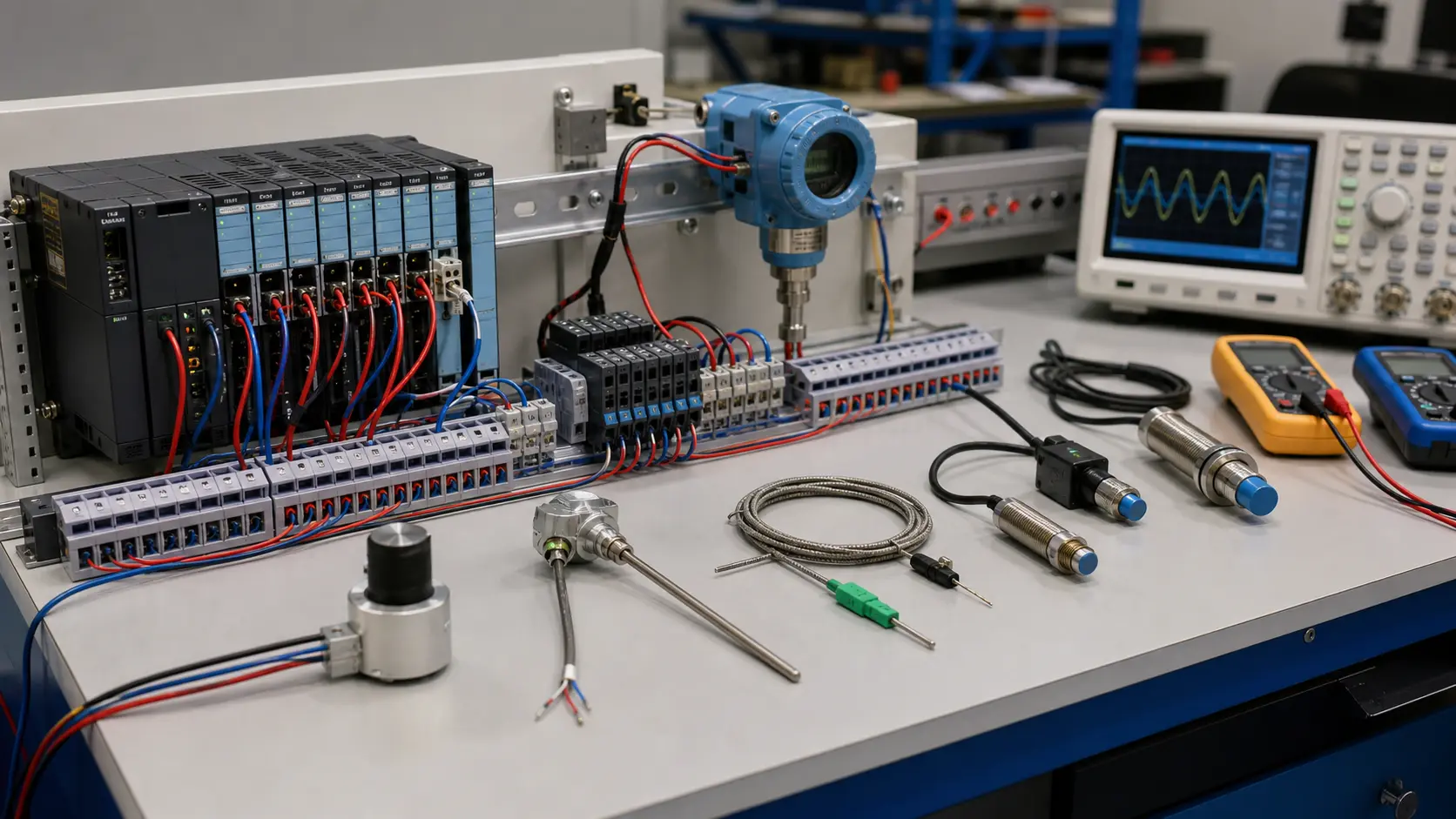
an isolated instrumentation bench connecting realistic sensors, signal conditioning, PLC channels and measurement evidence while studying industrial measurement loops, scaling and diagnostic evidence
System map / 02

NODE 01observable

Scope

Measurand, range, units, accuracy, process connection, sensor principle, transmitter output, loop power, PLC input, scaling and reference standard.

NODE 02observable

Signal path

Physical process through sensing element, transmitter, wiring, analog channel, raw data, engineering value, control decision and independent measurement.

NODE 03observable

Baseline practice

Low, midpoint and high conditions producing stable signal and scaled values with documented tolerance.

NODE 04observable

Edge cases

Under-range, over-range, open loop, reversed polarity, wrong input mode, noise, damping, failed reference, restart and stale value.

NODE 05observable

Fault practice

A process, sensor, calibration, transmitter, loop-power, wiring, channel, scaling, quality or interpretation mismatch.

NODE 06observable

Transfer to the job

The method transferred under qualified supervision using current instrument manuals, calibrated references and site procedures.

Answer surface / 07

What should an instrumentation course teach first?

Start with the physical variable, range and units, then trace the complete measurement loop before adding PLC scaling, alarms and control.

How is instrumentation competence assessed?

Use known input points, predicted readings, safe connection choices, raw and scaled evidence, fault diagnosis and an explanation of remaining calibration limits.