PLC Simulator

Incremental Encoder (Quadrature)

All sensor labs
Analog measurementintermediate lab

Incremental Encoder (Quadrature)

Converts shaft rotation into a pulse train — two channels (A and B) in quadrature give position and direction.

PLC addressHSC0
SignalPulse frequency
BenchLive + faults
FIELD DEVICE / 24 VDC

01 / Recognize it

What this sensor looks like

Learn the housing, active face, mounting, and connector before you meet it on a machine.

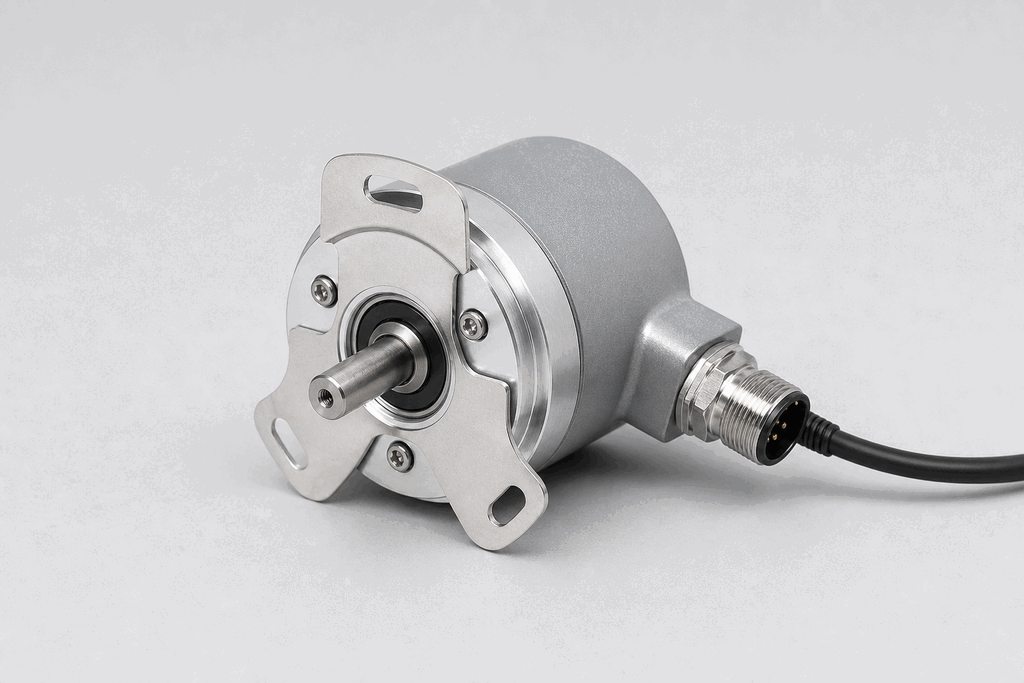
Representative real-world Incremental Encoder (Quadrature) hardware on an industrial workbench
Representative field appearance · form factors vary by manufacturer

Hardware recognition

Know what to look for

Use the silhouette, active face, and connection style to identify the device before checking its part number and datasheet.

Body and mounting
A round metal housing mounts concentrically to a shaft or motor.
Active face
A solid shaft, hollow bore, or coupling transfers machine rotation.
Cable and terminals
A multi-core cable carries A, B, index, supply, and shield connections.
Field rule: identify by appearance, then verify the exact wiring, range, approvals, and output type from the device label and datasheet.

02 / Understand the principle

Watch cause become a PLC signal

Follow the physical event through the sensing element and into the exact controller value.

Signal story / live loop

Incremental Encoder (Quadrature): cause to controller

Paused

Now showingPhysical event

Shaft rotates → A/B pulses alternate → HSC0 = 1,800 rpm

03 / Test and commission it

Commission it on the bench

Move the process, adjust the setpoint, invert the logic and inject faults. Watch the PLC value respond immediately.

Commissioning bench

Incremental Encoder (Quadrature)

24 VDCHSC0
9.60 mA
1050 rpm
1800 rpm

PLC channel

HSC0

RAW 9677

Engineering value

1050 rpm

Pulse frequency

Output logic
Inject a field fault

Channel healthy

Signal is inside the expected operating range

Terminals
ABZ / index

Commissioning note: Verify PPR, quadrature mode, and direction before using counts for position.

Field guide

An incremental encoder generates a pulse each time the shaft rotates by a fixed angle. The number of pulses per revolution (PPR) — also called resolution or line count — determines how finely position can be measured. A 1000 PPR encoder generates 1000 complete A-B cycles per shaft revolution.

Quadrature encoders have two output channels, A and B, shifted 90 degrees apart in phase. By examining which channel leads the other, the PLC can determine direction of rotation: if A leads B, the shaft is rotating forward; if B leads A, it is rotating backward. With quadrature decoding (counting both edges of A and B), the effective resolution is multiplied by four.

The Z channel (index pulse) produces one pulse per revolution at a fixed reference position. This allows the controller to re-home the axis after power-up without returning to a physical limit switch.

PLC high-speed counter (HSC) modules process encoder signals directly in hardware, decoding the quadrature and accumulating the count at speeds up to several MHz — far faster than the PLC scan cycle could handle in software.

Common output types are HTL (push-pull, 10-30 V, suitable for long cable runs) and TTL (differential RS-422, fast, noise-immune). Always match the encoder output type to the HSC module's input specification.

Use this when…

  • Measuring conveyor belt speed or position
  • Providing axis position feedback to a servo drive or PLC motion module
  • Counting print head rotations on a labelling machine

Where you will see it

Pick-and-place robot

Encoders on each servo axis stream position data to the motion controller, enabling precise multi-axis path following.

Palletiser conveyor

A line encoder on the main conveyor provides belt speed to the palletiser PLC, synchronising product pickup with belt motion.

Next skill

Connect it to PLC logic

Unlock PLC integration challenges

See plans