PLC Simulator

Mechanical Limit Switch

All sensor labs
Discrete inputbeginner lab

Mechanical Limit Switch

A mechanical contact switch that changes state when a moving part physically depresses its actuator.

PLC address%I0.3
SignalLever made
BenchLive + faults
FIELD DEVICE / 24 VDC

01 / Recognize it

What this sensor looks like

Learn the housing, active face, mounting, and connector before you meet it on a machine.

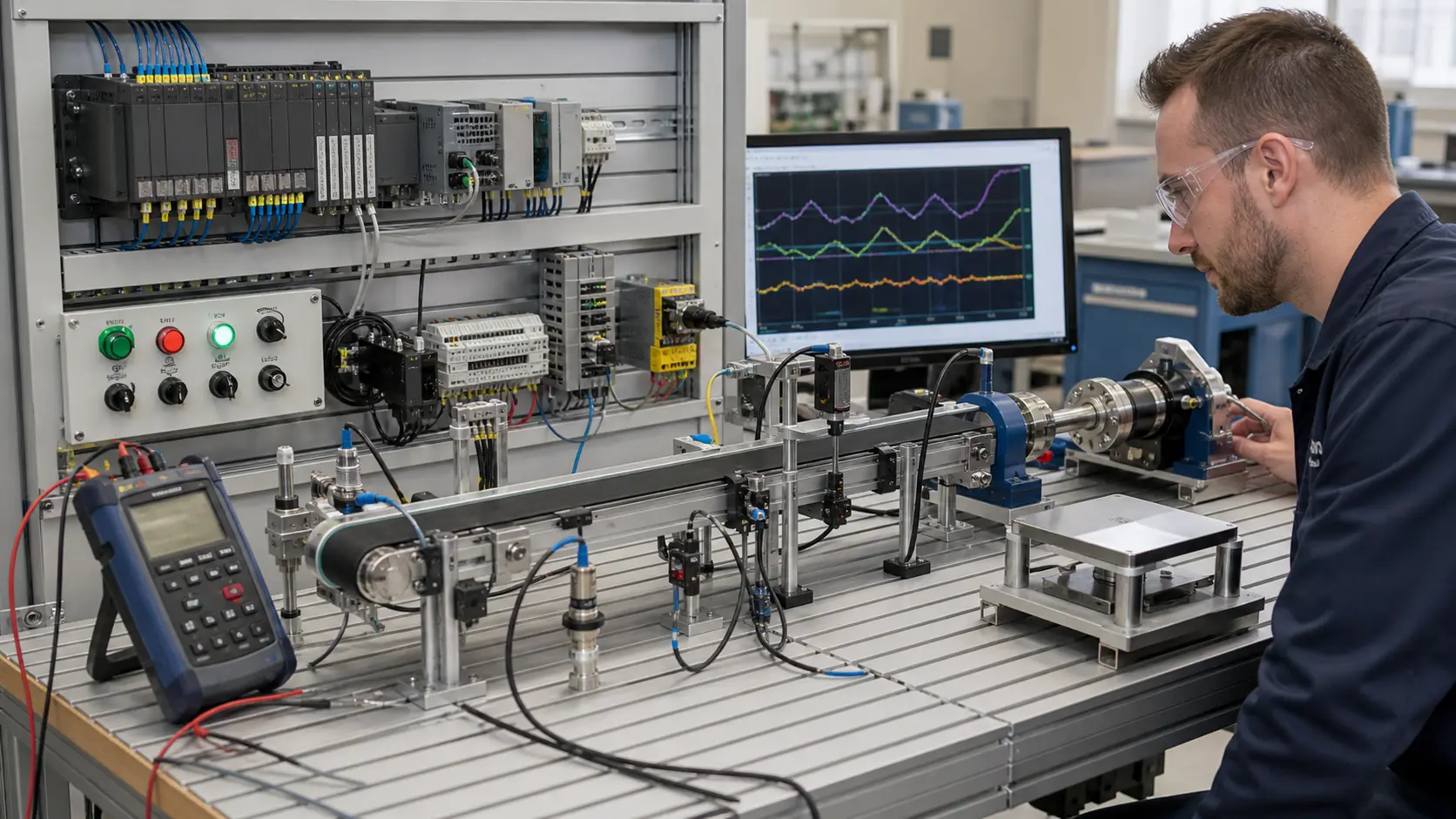
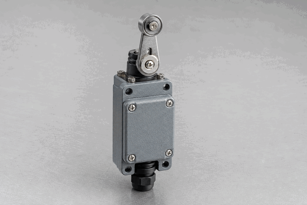
Representative real-world Mechanical Limit Switch hardware on an industrial workbench
Representative field appearance · form factors vary by manufacturer

Hardware recognition

Know what to look for

Use the silhouette, active face, and connection style to identify the device before checking its part number and datasheet.

Body and mounting
A rugged rectangular metal or polymer enclosure bolts directly to the machine.
Active face
A roller lever, plunger, whisker, or rotary head receives physical contact.
Cable and terminals
A cable gland or conduit entry leads to COM, NO, and NC contacts.
Field rule: identify by appearance, then verify the exact wiring, range, approvals, and output type from the device label and datasheet.

02 / Understand the principle

Watch cause become a PLC signal

Follow the physical event through the sensing element and into the exact controller value.

Signal story / live loop

Mechanical Limit Switch: cause to controller

Paused

Now showingPhysical event

Machine cam reaches the lever → Contacts change state → %I0.3 = 1

03 / Test and commission it

Commission it on the bench

Move the process, adjust the setpoint, invert the logic and inject faults. Watch the PLC value respond immediately.

Commissioning bench

Mechanical Limit Switch

24 VDC%I0.3
OFF
7 mm
11 mm

PLC channel

%I0.3

RAW 0

Engineering value

7 mm

Lever made

Output logic
Inject a field fault

Channel healthy

Signal is inside the expected operating range

Terminals
COMNONC

Commissioning note: Leave overtravel after the contact changes state so vibration cannot chatter the input.

Field guide

A mechanical limit switch is one of the oldest and most reliable sensors in industrial automation. When its actuator — a roller lever, plunger, or whisker — is physically depressed by a moving machine part, a set of electrical contacts inside changes state. The normally-open (NO) contact closes; the normally-closed (NC) contact opens.

PLCs read this as a discrete input: 0 V or 24 V on the input terminal. Unlike electronic sensors, limit switches work independently of ambient light, metal content, or electromagnetic interference. They can also switch higher voltages directly (up to 250 VAC in some models) for simple relay-logic panels.

Actuator types include the roller lever (used when a cam or dog pushes against a lever arm), the plunger (used when a surface presses down directly), and the whisker or antenna (used in low-force or thin-material applications). Rotary and adjustable-head variants allow flexible mounting.

When wiring to a PLC, most engineers use the NC contact for safety-critical functions (loss of continuity reveals a problem) and the NO contact for process signals. E-stop circuits and guard interlocks nearly always use NC wiring so that a broken cable registers as a fault rather than a safe state.

Limit switches require periodic inspection. The mechanical contacts wear after millions of operations and can arc when switching inductive loads unless a snubber circuit is fitted.

Use this when…

  • Detecting end-of-travel on a cylinder or axis
  • Confirming a door, guard, or gate is fully closed
  • Sequencing: waiting for a clamp to reach its closed position

Where you will see it

Hydraulic press

Roller-lever limit switches detect top and bottom dead centre of the ram, triggering PLC step transitions.

Conveyor gate

Plunger-style limit switches on diverter gates confirm the flap has fully stroked before allowing product to flow.

Next skill

Connect it to PLC logic

Unlock PLC integration challenges

See plans