PLC Simulator

Photoelectric Sensor (Photoeye)

All sensor labs
Discrete inputbeginner lab

Photoelectric Sensor (Photoeye)

Detects parts as they pass — outputs a discrete bit when something blocks the light beam.

PLC address%I0.0
SignalBeam received
BenchLive + faults
FIELD DEVICE / 24 VDC

01 / Recognize it

What this sensor looks like

Learn the housing, active face, mounting, and connector before you meet it on a machine.

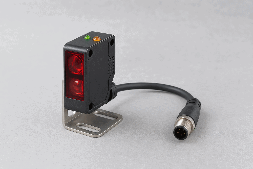
Representative real-world Photoelectric Sensor (Photoeye) hardware on an industrial workbench
Representative field appearance · form factors vary by manufacturer

Hardware recognition

Know what to look for

Use the silhouette, active face, and connection style to identify the device before checking its part number and datasheet.

Body and mounting
Usually a rectangular or threaded cylindrical body with a visible lens.
Active face
The optical window contains an emitter and receiver; alignment LEDs sit nearby.
Cable and terminals
Common 3-wire DC units use brown, blue, and black conductors or an M12 plug.
Field rule: identify by appearance, then verify the exact wiring, range, approvals, and output type from the device label and datasheet.

02 / Understand the principle

Watch cause become a PLC signal

Follow the physical event through the sensing element and into the exact controller value.

Signal story / live loop

Photoelectric Sensor (Photoeye): cause to controller

Paused

Now showingPhysical event

Carton enters the beam → Receiver loses light → %I0.0 = 1

03 / Test and commission it

Commission it on the bench

Move the process, adjust the setpoint, invert the logic and inject faults. Watch the PLC value respond immediately.

Commissioning bench

Photoelectric Sensor (Photoeye)

24 VDC%I0.0
ON
350 mm
430 mm

PLC channel

%I0.0

RAW 1

Engineering value

350 mm

Beam received

Output logic
Inject a field fault

Channel healthy

Signal is inside the expected operating range

Terminals
Brown +24 VBlue 0 VBlack OUT

Commissioning note: Set the switching point with at least 20% margin beyond the normal target position.

Field guide

A photoelectric sensor — often called a photoeye — detects objects without physical contact. It emits a beam of light (usually infrared) and monitors whether that beam reaches a receiver. When an object interrupts or reflects the beam, the sensor's output switches state, giving the PLC a discrete ON or OFF signal on an input address like %I0.0.

There are three common operating modes. In through-beam (or opposed) mode the emitter and receiver are separate units facing each other; an object crossing the gap breaks the beam. Retro-reflective mode uses a single housing that both emits and detects light bounced off a reflective target — the object breaks the return path. Diffuse mode has the emitter and receiver in the same housing and relies on light scattered back from the object's surface itself.

NPN sensors sink current (output pulls to 0 V), while PNP sensors source current (output pulls to supply voltage). Most modern PLC input cards accept either, but it is critical to match the sensor wiring to the input card's common polarity.

Photoeyes are used everywhere in manufacturing: counting parts on conveyors, detecting label presence on containers, confirming stack heights, and triggering reject gates. Their non-contact nature means no mechanical wear, and response times under 1 ms make them suitable for high-speed lines running hundreds of parts per minute.

Use this when…

  • Counting parts on a conveyor belt
  • Triggering a reject ejector when a defective part passes
  • Confirming a box is in position before a sealing head descends

Where you will see it

Bottling line

A retro-reflective photoeye counts bottles moving under a filling nozzle and signals the PLC to index the carousel.

Packaging

Diffuse photoeyes detect the leading and trailing edges of cardboard blanks on a case erector to control glue guns.

Next skill

Connect it to PLC logic

Unlock PLC integration challenges

See plans