PLC Simulator

Inductive Proximity Sensor

All sensor labs
Discrete inputbeginner lab

Inductive Proximity Sensor

Detects metallic targets without contact by sensing changes in an electromagnetic field.

PLC address%I0.1
SignalMetal detected
BenchLive + faults
FIELD DEVICE / 24 VDC

01 / Recognize it

What this sensor looks like

Learn the housing, active face, mounting, and connector before you meet it on a machine.

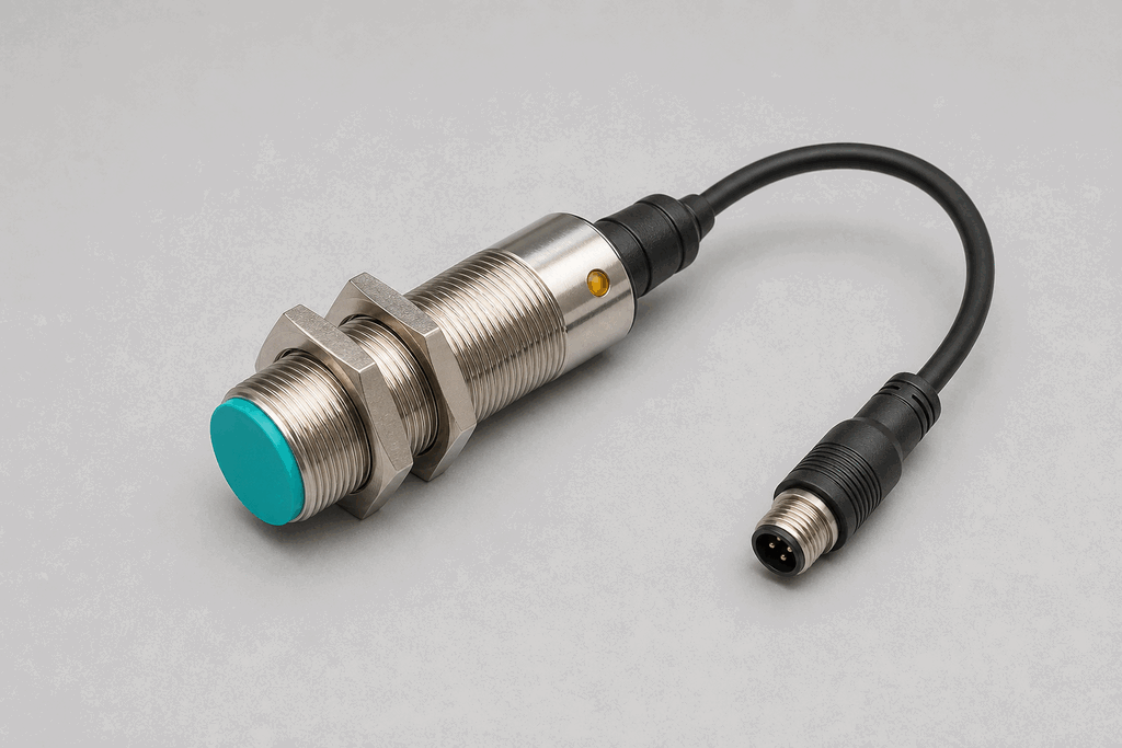
Representative real-world Inductive Proximity Sensor hardware on an industrial workbench
Representative field appearance · form factors vary by manufacturer

Hardware recognition

Know what to look for

Use the silhouette, active face, and connection style to identify the device before checking its part number and datasheet.

Body and mounting
Most inductive proximity sensors use a threaded M8, M12, M18, or M30 metal barrel.
Active face
The flat plastic end is the active face and must not be damaged by the target.
Cable and terminals
A rear cable or M12 connector carries 24 VDC and the switching output.
Field rule: identify by appearance, then verify the exact wiring, range, approvals, and output type from the device label and datasheet.

02 / Understand the principle

Watch cause become a PLC signal

Follow the physical event through the sensing element and into the exact controller value.

Signal story / live loop

Inductive Proximity Sensor: cause to controller

Paused

Now showingPhysical event

Steel flag moves closer → Oscillator is damped → %I0.1 = 1

03 / Test and commission it

Commission it on the bench

Move the process, adjust the setpoint, invert the logic and inject faults. Watch the PLC value respond immediately.

Commissioning bench

Inductive Proximity Sensor

24 VDC%I0.1
ON
7 mm
8 mm

PLC channel

%I0.1

RAW 1

Engineering value

7 mm

Metal detected

Output logic
Inject a field fault

Channel healthy

Signal is inside the expected operating range

Terminals
Brown +24 VBlue 0 VBlack PNP OUT

Commissioning note: Check the rated sensing distance against the actual target metal and mounting geometry.

Field guide

An inductive proximity sensor detects metallic objects without physical contact. Inside the sensing face is an oscillator coil that generates a high-frequency electromagnetic field. When a conductive target enters this field, eddy currents are induced in the metal, which damps the oscillator. The sensor's electronics detect this change and switch the output.

Sensing range depends on the target material. Mild steel gives the full rated range; aluminium and stainless steel reduce effective range by 30-50% due to their lower magnetic permeability. The manufacturer's datasheet always specifies a correction factor.

Shielded (flush-mountable) sensors contain the electromagnetic field within the face, allowing flush installation in a metal bracket. Unshielded sensors project a wider field and offer longer range, but require a metal-free zone around the sensing face.

Output wiring follows the same NPN/PNP conventions as photoeyes. Most industrial sensors are 3-wire: positive supply, negative/common, and signal. The signal wire connects to the PLC input.

Inductive prox sensors are the workhorse of factory automation — rugged, tolerant of oil and coolant, and immune to ambient light. They are not suitable for non-metallic targets; for plastics or liquids, a capacitive proximity sensor is the right choice.

Use this when…

  • Confirming a metal part is seated in a fixture
  • Detecting cam or gear tooth position for shaft feedback
  • Counting metal objects on a conveyor

Where you will see it

Automotive stamping

Inductive proximity sensors confirm steel blanks are seated correctly before a press descends, preventing tooling damage.

Machine tool

Shielded prox sensors detect the home position of CNC axes, providing repeatable reference points for every cycle.

Next skill

Connect it to PLC logic

Unlock PLC integration challenges

See plans