PLC Simulator

Intrinsic Safety in Hazardous Areas

All sensor labs
Safety circuitadvanced lab

Intrinsic Safety in Hazardous Areas

Intrinsically safe sensors limit the electrical energy in a hazardous area circuit so that no ignition-capable spark or hot surface can form — even under fault conditions. Zener barriers and galvanic isolators enforce the energy limits between the safe zone and the explosive atmosphere.

PLC address%IW74
SignalBarrier output
BenchLive + faults
FIELD DEVICE / 24 VDC

01 / Recognize it

What this sensor looks like

Learn the housing, active face, mounting, and connector before you meet it on a machine.

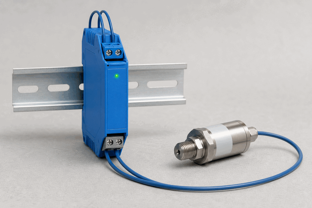
Representative real-world Intrinsic Safety in Hazardous Areas hardware on an industrial workbench
Representative field appearance · form factors vary by manufacturer

Hardware recognition

Know what to look for

Use the silhouette, active face, and connection style to identify the device before checking its part number and datasheet.

Body and mounting
The field instrument is paired with a slim DIN-rail barrier in the safe panel.
Active face
Blue terminals or cable identification commonly mark intrinsically safe circuits.
Cable and terminals
Field-side and safe-side terminals are physically segregated on the barrier.
Field rule: identify by appearance, then verify the exact wiring, range, approvals, and output type from the device label and datasheet.

02 / Understand the principle

Watch cause become a PLC signal

Follow the physical event through the sensing element and into the exact controller value.

Signal story / live loop

Intrinsic Safety in Hazardous Areas: cause to controller

Paused

Now showingPhysical event

Ex-area signal changes → Barrier limits energy → %IW74 = 16,589

03 / Test and commission it

Commission it on the bench

Move the process, adjust the setpoint, invert the logic and inject faults. Watch the PLC value respond immediately.

Commissioning bench

Intrinsic Safety in Hazardous Areas

24 VDC%IW74
9.60 mA
35 %
60 %

PLC channel

%IW74

RAW 9677

Engineering value

35 %

Barrier output

Output logic
Inject a field fault

Channel healthy

Signal is inside the expected operating range

Terminals
Field +/−IS barrierSafe-area AI

Commissioning note: Validate entity parameters, segregation, grounding, and the complete loop documentation.

Field guide

Intrinsic safety (IS) is an explosion protection technique that restricts the electrical energy available in a hazardous area circuit below the minimum ignition energy of the surrounding atmosphere — under both normal operation and specified fault conditions.

Hazardous areas are classified by the likelihood of an explosive atmosphere being present. Zone 0 is a place where an explosive gas atmosphere is present continuously or for long periods. Zone 1 means it is likely to occur during normal operation. Zone 2 covers locations where it is not likely in normal operation but may occur in abnormal conditions. The equivalent dust zones are Zone 20, 21, and 22.

The key hardware element is the Zener barrier, wired in the safe area between the control system and the field device. A barrier contains two or three Zener diodes that clamp voltage below the certified limit, a resistor that limits current, and a fuse. If a fault drives the supply above the Zener knee voltage, the diodes conduct and the fuse blows — preventing excess energy from reaching the hazardous area. Galvanic isolators use transformer or optical coupling and offer a higher safe-area voltage range, eliminating the need for a high-integrity safety earth.

Cable capacitance and inductance matter because stored energy in a cable can feed a spark after the source is disconnected. IS certification documents include maximum allowable cable capacitance (typically 83–150 nF) and inductance (typically 1–4 mH) — the installed cable parameters must stay within these limits.

Two major certification schemes govern IS equipment. ATEX (from the French ATmosphères EXplosibles) is mandated by EU Directive 2014/34/EU and is required for equipment placed on the EU market. IECEx is the International Electrotechnical Commission's voluntary certification scheme, accepted in South Africa (SANS), Australia, and over 50 other countries. Both schemes assess against IEC 60079-11 (intrinsic safety) and require third-party testing by a notified body or ExCB. Equipment carries a certification mark, an Ex code (for example Ex ia IIC T4 Gb), and a certificate number.

Use this when…

  • When installing sensors inside Zone 0, Zone 1, or Zone 2 classified areas where flammable gases, vapours, or dusts are present — the energy of any spark in the circuit must be insufficient to ignite the surrounding atmosphere
  • When your process requires the sensor to remain powered during operation and you cannot interrupt the circuit for maintenance — intrinsic safety allows live work in the hazardous area because energy levels are always below the minimum ignition energy
  • When regional regulations or insurance require ATEX-certified equipment for EU installations, or IECEx-certified equipment for international projects in South Africa, Australia, or the Middle East

Where you will see it

Oil and gas refinery

Level transmitters inside Zone 1 hydrocarbon vessels use Zener barriers to cap loop energy at 1.2 W and 28 V, ensuring the 4-20 mA signal cable cannot deliver enough energy to ignite the vapour cloud even if the cable is short-circuited or open-circuited.

Grain handling facility

Proximity sensors on bucket-elevator take-up pulleys are classified Zone 21 (combustible grain dust). IS-rated inductive sensors with galvanic isolators prevent dust-cloud ignition from the sensor wiring, satisfying the EU ATEX Directive 2014/34/EU Category 2D requirement.

Concept and commissioning lab

This topic is taught through the live bench and reference rather than a separate ladder challenge. Continue to a physical sensor when you are ready to wire a PLC input.