IO-Link Smart Sensors
IO-Link turns an ordinary point-to-point sensor cable into a bidirectional digital channel — unlocking remote parameterisation, rich diagnostics, and event data alongside the normal process value.
01 / Recognize it
What this sensor looks like
Learn the housing, active face, mounting, and connector before you meet it on a machine.
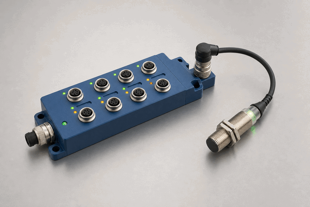
Hardware recognition
Know what to look for
Use the silhouette, active face, and connection style to identify the device before checking its part number and datasheet.
- Body and mounting
- The field sensor may look conventional; the IO-Link master is a multi-port IP67 block.
- Active face
- Status LEDs identify ports, device communication, and diagnostic state.
- Cable and terminals
- Standard unshielded M12 sensor cables carry L+, L−, and the C/Q data line.
02 / Understand the principle
Watch cause become a PLC signal
Follow the physical event through the sensing element and into the exact controller value.
Signal story / live loop
IO-Link Smart Sensors: cause to controller
Now showingPhysical event
Process condition changes → Cyclic frame is assembled → IO-LINK PD = 70%
03 / Test and commission it
Commission it on the bench
Move the process, adjust the setpoint, invert the logic and inject faults. Watch the PLC value respond immediately.
Commissioning bench
IO-Link Smart Sensors
PLC channel
IO-Link master
RAW 9677
Engineering value
35 %
Cyclic data + diagnostics
Channel healthy
Signal is inside the expected operating range
Commissioning note: Store parameter sets in the master so a replacement device can be restored automatically.
Field guide
IO-Link is a point-to-point communication standard (IEC 61131-9) that runs over the same three-wire unshielded cable already used for standard sensors. The cable carries 24 V power, the conventional SIO (standard IO) bit, and the IO-Link serial channel on a single conductor — no extra wiring, no fieldbus topology, no star cabling required.
The IO-Link master is a module that sits on a fieldbus (PROFINET, EtherNet/IP, EtherCAT) and provides four to eight ports, each of which connects to one IO-Link device. Every port is independently configurable: you can run port 1 as a conventional digital input while ports 2 and 3 run full IO-Link at COM3 speed.
Three baud rates are defined: COM1 at 4.8 kbps for simple devices, COM2 at 38.4 kbps for most sensors, and COM3 at 230.4 kbps for high-speed process data. A modern inductive or photoelectric sensor typically negotiates COM2 automatically during the port activation handshake.
The data channel is split into three parts. Process data carries the primary measurement — the bit or word value the PLC reads every scan. Service data is on-demand read/write access to device parameters such as switching point, output logic, and filter time. The device IODD (IO Device Description) file describes every readable and writable parameter in a machine-readable XML format that engineering tools use to build configuration UIs automatically.
Diagnostics are what make IO-Link compelling for maintenance teams. A device can push an event asynchronously — lens dirty, target too close, supply voltage low — without waiting for the PLC to poll it. The master forwards the event to the controller within one IO-Link cycle. This turns a silent trip into an actionable alarm with a plain-English description.
Use this when…
- When you need to read diagnostic data like 'lens dirty' or 'alignment lost' from a sensor without walking to the machine
- When you want to change sensor parameters — range, hysteresis, output polarity — from the PLC program without physically re-teaching the device
- When you're building a system where rapid sensor swap-out is important and the replacement device must self-configure from stored IODD parameters
Where you will see it
Automotive body shop
IO-Link photoelectric sensors on welding fixtures report lens contamination directly to the SCADA system; maintenance is dispatched before a false trip ever occurs.
Pharmaceutical filling line
Inductive IO-Link sensors report their internal temperature alongside the part-present bit; a rising trend flags a ventilation problem before it causes measurement drift.
Concept and commissioning lab
This topic is taught through the live bench and reference rather than a separate ladder challenge. Continue to a physical sensor when you are ready to wire a PLC input.