Strain Gauge / Load Cell
Measures mechanical force or weight by detecting tiny resistance changes in metal foil bonded to a structural element.
01 / Recognize it
What this sensor looks like
Learn the housing, active face, mounting, and connector before you meet it on a machine.
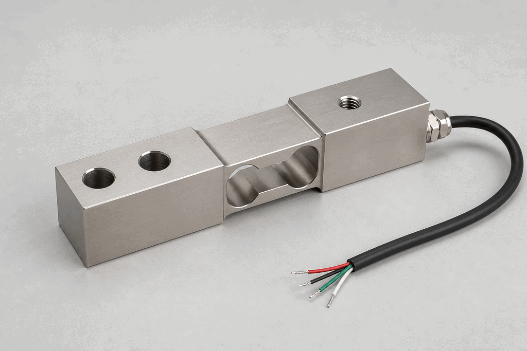
Hardware recognition
Know what to look for
Use the silhouette, active face, and connection style to identify the device before checking its part number and datasheet.
- Body and mounting
- Industrial load cells are machined metal beams, discs, or canisters.
- Active face
- The gauge itself is bonded inside or under a protected cover on the flexure.
- Cable and terminals
- A shielded multi-core cable carries excitation and millivolt signal pairs.
02 / Understand the principle
Watch cause become a PLC signal
Follow the physical event through the sensing element and into the exact controller value.
Signal story / live loop
Strain Gauge / Load Cell: cause to controller
Now showingPhysical event
Vessel load increases → Bridge unbalances → %IW70 = 3,200 kg
03 / Test and commission it
Commission it on the bench
Move the process, adjust the setpoint, invert the logic and inject faults. Watch the PLC value respond immediately.
Commissioning bench
Strain Gauge / Load Cell
PLC channel
%IW70
RAW 9677
Engineering value
1750 kg
Bridge signal
Channel healthy
Signal is inside the expected operating range
Commissioning note: Zero the empty system, then span-calibrate with a traceable test load.
Field guide
A strain gauge is a sensor whose electrical resistance changes when it is mechanically stretched or compressed. The sensing element is a thin metallic foil (usually constantan alloy) bonded to a backing material. When the surface it is bonded to deforms, the foil stretches or compresses, changing its length and cross-section and therefore its resistance.
A single strain gauge produces only a tiny resistance change — a few ohms at full load. To convert this into a useful signal, four gauges are wired in a Wheatstone bridge configuration. Two gauges are in tension and two in compression, which doubles sensitivity and cancels out temperature errors. The bridge output is typically 2-3 mV per volt of excitation voltage.
A load cell is a complete force-measurement device: it consists of a precisely machined metal element (the spring element) with strain gauges bonded at positions of maximum stress. Common geometries include the S-beam (tension/compression), bending beam (platform scales), and compression canister (silo weighing).
The signal conditioner amplifies the millivolt bridge output to the standard 4-20 mA or 0-10 V range that the PLC analog input card accepts. High-quality conditioners include features like zero calibration, span adjustment, and digital filtering to remove mechanical vibration noise.
PLC scaling follows the same linear scaling formula as any other analog sensor: engineering_value = (raw_count / max_count) * (max_EU - min_EU) + min_EU.
Use this when…
- Weighing ingredients in a batch recipe system
- Monitoring tension in a web or cable
- Detecting overload on a structural frame or lifting device
Where you will see it
Fill-by-weight
Load cells under a fill hopper feed the PLC a continuous weight signal; filling stops when the target mass is reached.
Crane overload
Load cells on the hoist rope terminate lifting and trigger an alarm when load exceeds the rated safe working limit.
Next skill
Connect it to PLC logic
Unlock PLC integration challenges