PLC Simulator

Thermocouple (Type K)

All sensor labs
Analog measurementintermediate lab

Thermocouple (Type K)

Two dissimilar metal wires joined at a measurement junction produce a millivolt signal proportional to temperature.

PLC address%IW66
SignalThermocouple input
BenchLive + faults
FIELD DEVICE / 24 VDC

01 / Recognize it

What this sensor looks like

Learn the housing, active face, mounting, and connector before you meet it on a machine.

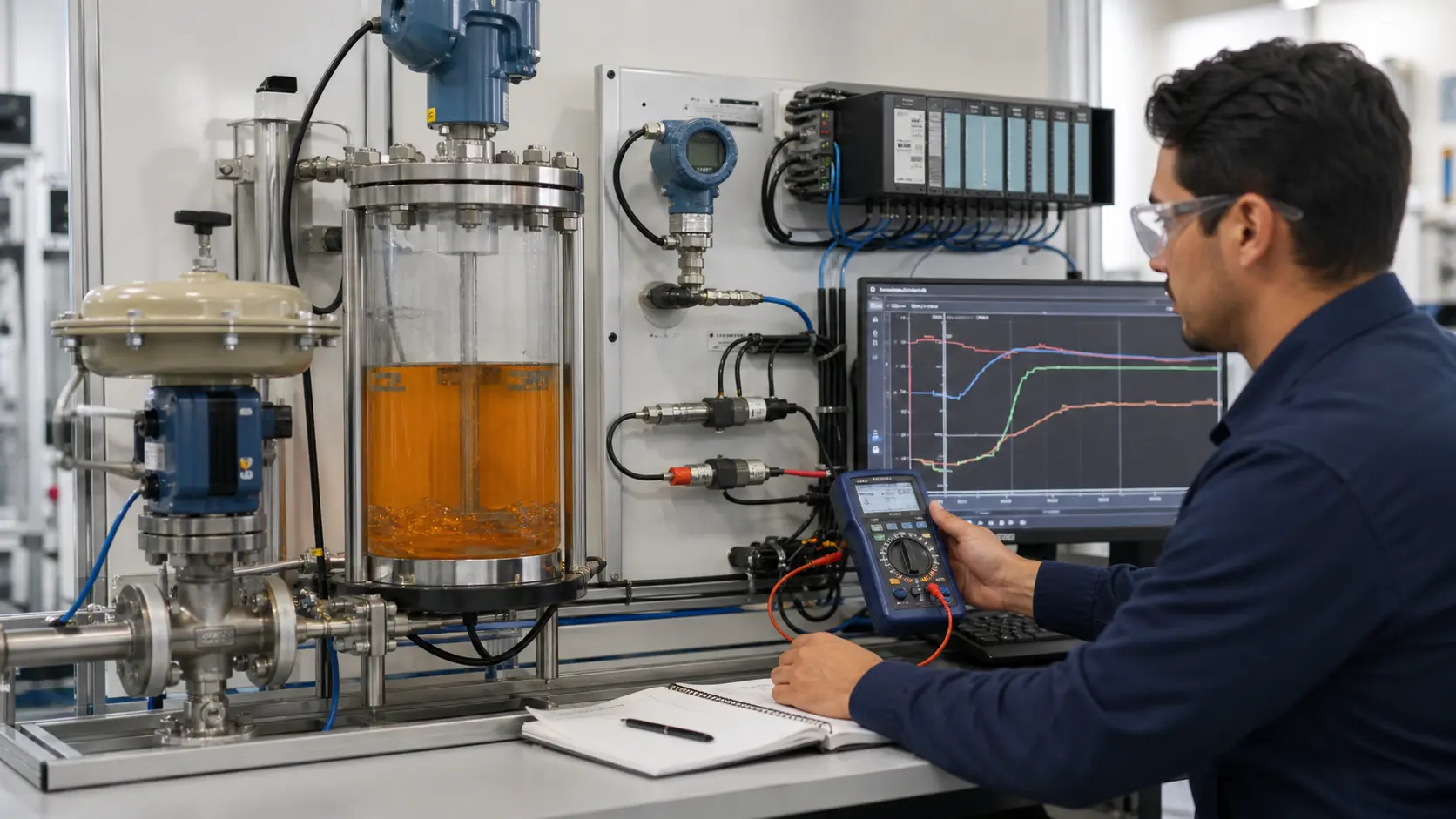
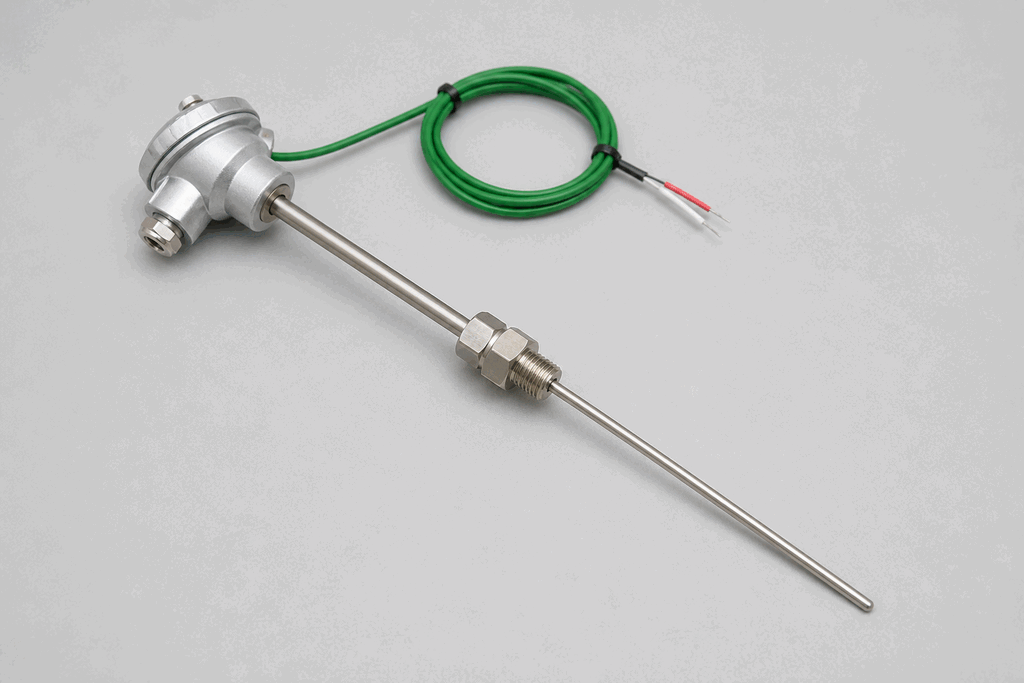
Representative real-world Thermocouple (Type K) hardware on an industrial workbench
Representative field appearance · form factors vary by manufacturer

Hardware recognition

Know what to look for

Use the silhouette, active face, and connection style to identify the device before checking its part number and datasheet.

Body and mounting
A metal sheath or probe terminates in a small connection head or flexible lead.
Active face
The measuring junction is at or near the probe tip.
Cable and terminals
Extension wire colors depend on thermocouple type and regional standard.
Field rule: identify by appearance, then verify the exact wiring, range, approvals, and output type from the device label and datasheet.

02 / Understand the principle

Watch cause become a PLC signal

Follow the physical event through the sensing element and into the exact controller value.

Signal story / live loop

Thermocouple (Type K): cause to controller

Paused

Now showingPhysical event

Hot junction heats up → Seebeck voltage rises → %IW66 = 700 °C

03 / Test and commission it

Commission it on the bench

Move the process, adjust the setpoint, invert the logic and inject faults. Watch the PLC value respond immediately.

Commissioning bench

Thermocouple (Type K)

24 VDC%IW66
9.60 mA
388 °C
700 °C

PLC channel

%IW66

RAW 9677

Engineering value

388 °C

Thermocouple input

Output logic
Inject a field fault

Channel healthy

Signal is inside the expected operating range

Terminals
TC+TC−Shield at panel

Commissioning note: Use the correct extension alloy and input type; copper cable creates another junction.

Field guide

A thermocouple is one of the most widely used temperature sensors in industry. It works on the Seebeck effect: when two dissimilar metals are joined at both ends and one junction is at a different temperature than the other, a small voltage is produced. This voltage — typically a few millivolts at industrial temperatures — is measured and converted to a temperature reading.

Type K thermocouples use chromel and alumel as the two metals. They are the most common type because of their wide temperature range (-200 °C to +1260 °C) and relatively linear output curve (approximately 41 µV/°C at mid-range). Other types (J, T, E, N, R, S, B) trade off range, accuracy, and cost differently.

Cold junction compensation (CJC) is critical. The thermocouple voltage represents the temperature difference between the hot measurement junction and the cold reference junction — usually where the thermocouple wires connect to the PLC module terminals. The module measures ambient temperature at the terminal block and automatically adds the correction.

Thermocouple extension wire must use the same metal pair as the thermocouple itself. Using copper wire to extend a thermocouple introduces a new thermocouple junction at the connection point, generating a spurious error voltage.

PLCs read thermocouples through dedicated thermocouple input modules (e.g. Siemens SM331 TC, Allen-Bradley 1756-IT6I) that include the instrumentation amplifier, cold junction sensor, and linearisation lookup table. The module outputs a scaled integer representing temperature in tenths of a degree.

Use this when…

  • Measuring process temperatures from -200 °C to +1260 °C
  • Monitoring furnace, oven, or kiln temperature for PID control
  • Detecting overtemperature on motors, bearings, or transformers

Where you will see it

Heat treatment

Type K thermocouples inside quench furnaces feed the PLC PID block that controls gas burner output, holding soak temperature within ±2 °C.

Plastics injection moulding

Multiple thermocouples along an injection barrel barrel zones allow independent zone control of melt temperature.

Next skill

Connect it to PLC logic

Unlock PLC integration challenges

See plans