PLC Simulator

Ultrasonic Distance Sensor

All sensor labs
Analog measurementintermediate lab

Ultrasonic Distance Sensor

Measures distance by timing an ultrasonic pulse echo — output is proportional to the target distance.

PLC address%IW72
SignalMeasured distance
BenchLive + faults
FIELD DEVICE / 24 VDC

01 / Recognize it

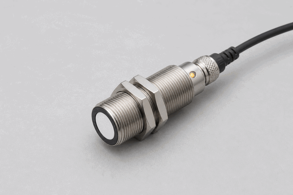
What this sensor looks like

Learn the housing, active face, mounting, and connector before you meet it on a machine.

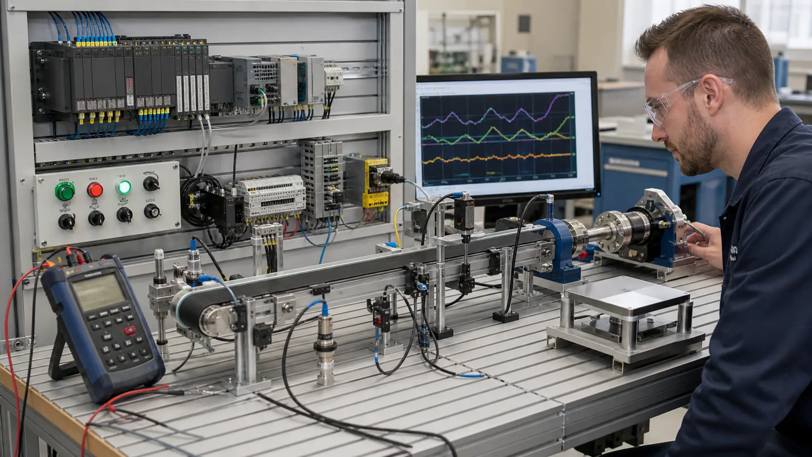
Representative real-world Ultrasonic Distance Sensor hardware on an industrial workbench
Representative field appearance · form factors vary by manufacturer

Hardware recognition

Know what to look for

Use the silhouette, active face, and connection style to identify the device before checking its part number and datasheet.

Body and mounting
Usually a cylindrical or rectangular housing with one or two round acoustic faces.
Active face
The transducer face must point squarely at the target and remain unobstructed.
Cable and terminals
An M12 connector or cable carries power and switching or analog output.
Field rule: identify by appearance, then verify the exact wiring, range, approvals, and output type from the device label and datasheet.

02 / Understand the principle

Watch cause become a PLC signal

Follow the physical event through the sensing element and into the exact controller value.

Signal story / live loop

Ultrasonic Distance Sensor: cause to controller

Paused

Now showingPhysical event

Liquid surface moves → Echo time changes → %IW72 = 2,600 mm

03 / Test and commission it

Commission it on the bench

Move the process, adjust the setpoint, invert the logic and inject faults. Watch the PLC value respond immediately.

Commissioning bench

Ultrasonic Distance Sensor

24 VDC%IW72
9.60 mA
1400 mm
2600 mm

PLC channel

%IW72

RAW 9677

Engineering value

1400 mm

Measured distance

Output logic
Inject a field fault

Channel healthy

Signal is inside the expected operating range

Terminals
Brown +24 VBlue 0 VAnalog OUT

Commissioning note: Keep the target outside the blind zone and avoid angled surfaces that deflect the echo.

Field guide

An ultrasonic sensor measures distance by emitting a burst of high-frequency sound (40-400 kHz, above the range of human hearing) and measuring the time it takes for the echo to return from a target surface. Since the speed of sound in air is approximately 343 m/s, the round-trip time divided by two gives the distance: distance = (time × speed_of_sound) / 2.

The sensor has a blind zone — a minimum distance near the face where the echo returns before the transmitter has switched to receive mode. Typical blind zones are 30-300 mm depending on the model. Targets closer than the blind zone are not detected reliably.

The beam width is another key specification. Wide beams average the return from a larger area, which can give misleading readings when a target has an irregular or angled surface. Narrow-beam models (pencil-beam) are used for precise measurement of irregular objects.

Output options include 4-20 mA (proportional to distance), 0-10 V, or discrete switching (when the target enters a set window). Most modern sensors also offer IO-Link for digital configuration without changing the wiring.

Temperature affects the speed of sound (it increases with temperature by about 0.6 m/s per °C). Premium sensors include a temperature compensation circuit; budget models require an ambient temperature correction factor in the PLC scaling.

Use this when…

  • Measuring fill level in a tank without contacting the liquid
  • Detecting pallet height or stack level on a conveyor
  • Providing distance feedback for a robotic arm or gantry

Where you will see it

Silo level

Ultrasonic sensors mounted at the top of grain silos measure the distance to the grain surface, giving continuous volumetric fill level.

Web tension

Ultrasonic sensors on dancer rollers measure displacement, feeding a PLC PID block that controls unwind brake torque.

Next skill

Connect it to PLC logic

Unlock PLC integration challenges

See plans