A PLC controls temperature by reading a sensor — usually an RTD or thermocouple — through an analog input, comparing that measured value (PV) to a setpoint (SP), and switching a heater or cooler output to drive the two together. The simplest version is on/off control: turn the heater on when the temperature drops below the setpoint and off when it rises above it. The more precise version is PID control, which modulates the output to hold the temperature steady. This guide shows both, with a worked temperature control using PLC ladder diagram you can build in minutes.
The hardware: from sensor to heater
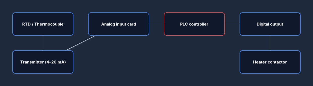
Every PLC temperature controller follows the same signal chain. A temperature sensor sits in the process. Its signal is conditioned into a standard analog signal — most commonly 4–20 mA or a voltage — and wired into an analog input card on the PLC. The PLC scales that raw count into engineering units (°C or °F), runs your control logic, and drives a digital or analog output that switches the heating element through a contactor or solid-state relay.
Two sensor types dominate:
- RTDs (e.g. Pt100) are accurate and stable over moderate ranges — great for ovens, tanks and HVAC.
- Thermocouples (Type K, J, etc.) cover a much wider range and survive higher temperatures, at the cost of a little accuracy and more noise.
Whichever you use, the first job in the PLC is scaling the raw input count into a real temperature. Get the scaling wrong and every decision the loop makes afterwards is wrong too.
Closed-loop control: PV vs SP
Temperature control is a closed loop. The PLC does not just fire the heater blindly; it constantly measures the result and feeds it back. The measured process value (PV) is compared to the setpoint (SP), and the difference — the error — tells the controller what to do. Heating raises the PV, the sensor reports the change, and the loop closes again on the next scan.
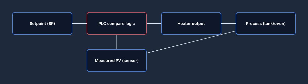
Because the PLC re-evaluates this every scan, the behavior you get depends entirely on the logic you put between PV and the output. That logic is where on/off and PID part ways.
On/off control with hysteresis
The most common starting point is on/off control. The rule is simple: if the temperature is below the setpoint, heat; if it is above, stop. But a naïve "below SP → on, above SP → off" rule causes the heater to switch on and off rapidly the instant the PV sits exactly on the setpoint — known as chattering — which wears out contactors fast.
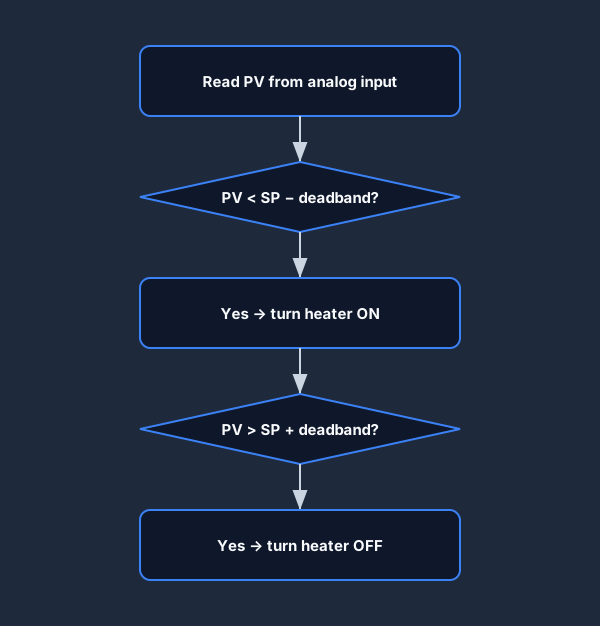
The fix is a deadband (also called hysteresis): a small band around the setpoint where nothing changes. The heater turns on only when the PV falls below SP − deadband, and turns off only when it climbs above SP + deadband. The result is a slow, controlled cycle instead of a buzzing relay.
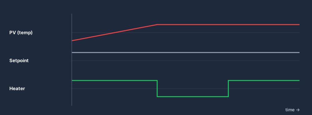
You can see in the timing diagram that the temperature gently saws up and down between the two limits while the heater output cycles. The wider the deadband, the slower the cycle and the more the temperature wanders; the narrower it is, the tighter the control but the more often the heater switches.
The ladder diagram
Here is the heart of a temperature control using PLC ladder diagram. A comparison instruction (LES, less than) checks whether the scaled PV is below the lower deadband limit. When it is — and the system is in Auto mode — the Heater output energises.
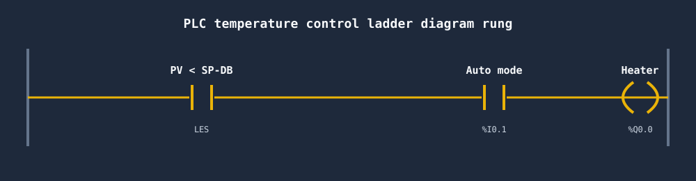
In a real program you pair this rung with a second rung that de-energises the heater (or uses a seal-in latch) once the PV climbs above SP + deadband. The compare block does the analog heavy lifting; the rest is ordinary contacts and a coil. Add an Auto/Manual selector and a high-temperature interlock and you have a controller that is safe to run.
The full control decision the PLC makes each scan looks like this:
On/off vs PID control
On/off control is easy to write and almost impossible to get badly wrong, but the temperature always oscillates — it never truly settles on the setpoint. For processes that need precision (a reflow oven, an extruder barrel, a lab bath), you step up to PID control.
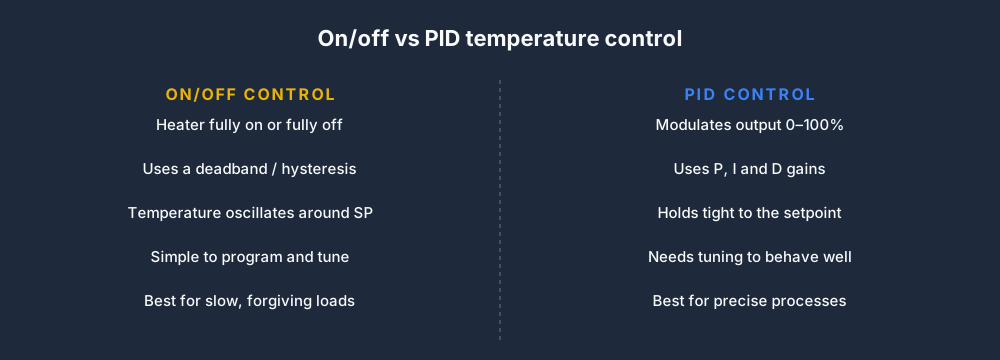
PID modulates the output continuously from 0–100% based on three terms: Proportional (how big the error is now), Integral (how long the error has persisted) and Derivative (how fast the error is changing). Tuned well, a PID loop parks the temperature on the setpoint and holds it there. The trade-off is that PID needs tuning, and bad gains can make a loop overshoot or oscillate worse than on/off ever would. If you want the full treatment, see our guide to PID control for PLCs.
A third option: time-proportional control
There is a useful middle ground. Time-proportional control takes a PID-style 0–100% command but expresses it as a duty cycle on a digital output — say, on for 7 seconds out of every 10 for a 70% command. This lets you drive a cheap contactor or solid-state relay with near-PID smoothness, without an analog output card. It is the standard approach in many industrial temperature controllers.
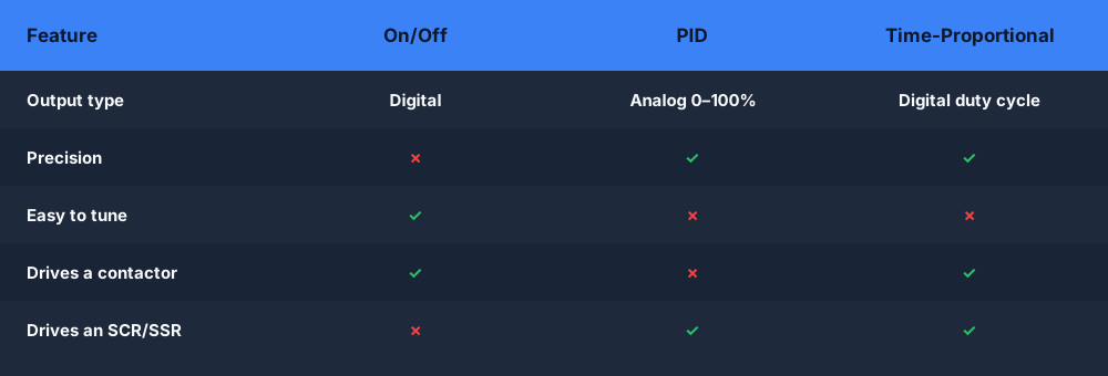
Pick the method to match the process: on/off for slow, forgiving loads; PID with an analog output (SCR drive) for the tightest control; time-proportional when you need PID-like results but only have a digital output and an SSR.
Practical tips
A few habits separate a temperature loop that works on the bench from one that survives on the plant floor.
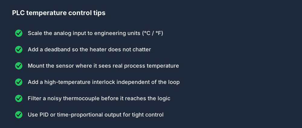
The two that catch the most people: always scale the analog input properly before any logic touches it, and always add a separate high-temperature interlock that cuts the heater independently of the control loop. If your loop logic ever fails, that interlock is what stops a runaway. Temperature loops also show up constantly in building systems — if that is your world, our HVAC PLC programming guide builds on exactly these patterns.
Build it in your browser
The fastest way to understand a temperature loop is to watch the PV climb, hit the deadband, and watch the heater output flip. You can wire up this exact rung — analog compare, deadband, Auto/Manual, interlock — in the free browser PLC simulator, no hardware required. Change the deadband and watch the cycle time change in real time; it makes hysteresis click in a way no diagram can.
FAQ
How does a PLC control temperature? A PLC reads a temperature sensor (RTD or thermocouple) through an analog input, scales the signal to engineering units, compares the measured value to a setpoint, and switches a heater or cooler output to drive the temperature toward the setpoint. It repeats this every scan as a closed loop.
What is on/off temperature control in a PLC? On/off control turns the heater fully on when the temperature is below the setpoint and fully off when it is above. A deadband (hysteresis) around the setpoint prevents the output from chattering, so the temperature cycles slowly between the two limits.
What is hysteresis or deadband in temperature control?
It is a small band around the setpoint where the output does not change. The heater turns on below SP − deadband and off above SP + deadband, which stops rapid on/off switching that would otherwise wear out the contactor.
On/off vs PID — which should I use? Use on/off (with a deadband) for slow, forgiving processes where some oscillation is fine. Use PID when you need the temperature held tightly on the setpoint. Time-proportional control is a middle ground that gives PID-like results from a digital output driving an SSR.
What sensor is used for PLC temperature control? Most loops use an RTD (such as a Pt100) for accurate, stable readings over moderate ranges, or a thermocouple (Type K, J, etc.) for very high or wide temperature ranges. Both feed the PLC through an analog input, usually as a 4–20 mA signal.