PLC Simulator
PLC field notesladder logic

Ladder Logic vs Structured Text: Which One to Learn First

Ladder logic is graphical and widely supported; structured text is textual and powerful for maths. Compare syntax, use cases, and job market demand to choose your first PLC language.

PLC Simulation Software9 min read

TL;DR

  • Ladder logic (LD): graphical, relay-diagram style, universal vendor support, preferred for discrete machine control and field troubleshooting — ~70% of North American job postings require it.
  • Structured text (ST): textual, Pascal-like, preferred for maths, loops, and complex algorithms — essential once you move beyond basic I/O.
  • Which to learn first? Ladder logic — almost every employer and every PLC supports it. Add structured text once you can write a solid motor starter.
  • Both are IEC 61131-3 standard languages and can be mixed in the same program.

Most people learning PLC programming hit the same question within the first week: should I start with ladder logic or structured text?

Short answer: start with ladder logic. It is the most widely deployed language in industry, almost every PLC vendor supports it, and the graphical relay-style syntax makes the logical behaviour visible without prior programming experience. Once you can write a solid motor starter and a timer sequence in ladder, picking up structured text takes days, not weeks.

But the longer answer depends on your background and your target industry — and both languages are worth understanding. Here is a full comparison.
Ladder logic vs structured text comparison — which PLC language to learn first

What Is Ladder Logic?

Ladder Diagram (LD) is a graphical programming language modelled on the relay logic circuits that PLCs replaced in the 1970s. A program is a series of horizontal rungs drawn between two vertical rails (representing power rails). Each rung contains contacts (input conditions) in series or parallel and one or more coils (outputs or memory bits) on the right.

|--[ContactA]--[ContactB]--( CoilX )--|
|--[ContactC]--            ( CoilY )--|

Rung 1 says: "CoilX is true if ContactA AND ContactB are both true." Rung 2 says: "CoilY is true if ContactC is true."

The mental model is simple: current flows from left to right when all series contacts are closed. Electricians and maintenance technicians with relay-panel experience can read ladder immediately.

A real motor start/stop is the canonical example: a Start contact and a normally-closed Stop contact drive a Motor coil that seals itself in.
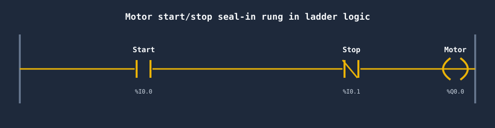
Motor start/stop seal-in rung in ladder logic with Start, Stop and Motor coil

The exact same logic in structured text is a single assignment:

(* Motor start/stop seal-in — structured text equivalent *)
Motor := (Start OR Motor) AND NOT Stop;

Notice what each form makes obvious: the rung shows the flow of logic at a glance, while the structured text states the condition in one compact line.

What Is Structured Text?

Structured Text (ST) is a high-level, Pascal-like textual language standardised in IEC 61131-3. It supports:

  • Conditional logic: IF / ELSIF / ELSE / END_IF
  • Loops: FOR, WHILE, REPEAT
  • Case statements: CASE ... OF
  • Mathematical operators: +, -, *, /, MOD, **
  • All standard IEC data types: BOOL, INT, REAL, STRING, ARRAY, STRUCT
(* PID pre-heat temperature control — structured text *)
Error := Setpoint - ProcessTemp;
Integral := Integral + (Error * SampleTime);
Derivative := (Error - PrevError) / SampleTime;

Output := Kp * Error + Ki * Integral + Kd * Derivative;
Output := MAX(0.0, MIN(100.0, Output));  (* Clamp 0–100% *)

PrevError := Error;

This code is compact, precise, and reads like code — because it is. Developers with Python, C, or Java backgrounds are productive in structured text in hours.

Side-by-Side Comparison
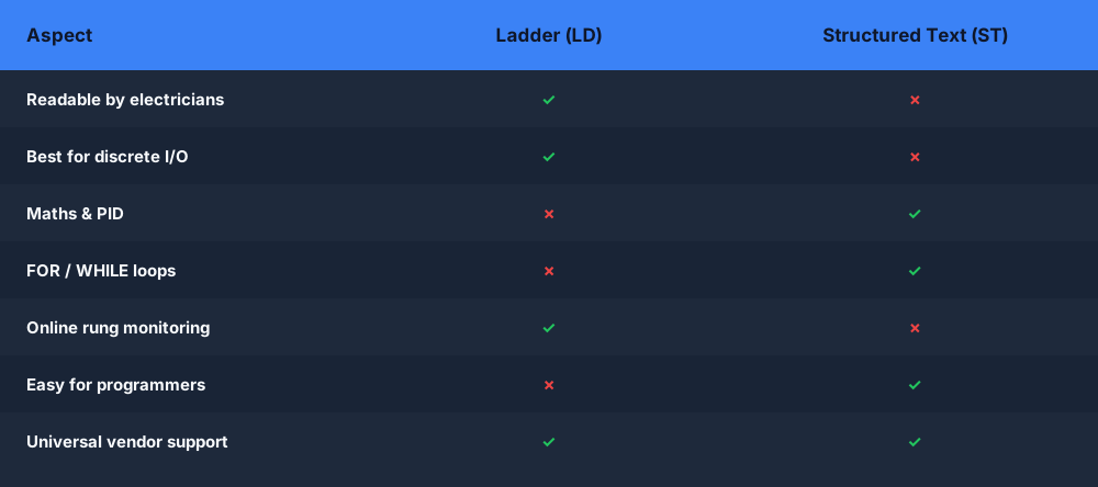
Ladder logic vs structured text comparison table of readability, maths, loops, maintenance and vendor support

Reference tableSwipe
Ladder DiagramStructured Text
SyntaxGraphical rungsText, Pascal-like
Best forDiscrete I/O, motor control, interlocksMaths, loops, complex algorithms, PID
Readability for electriciansHighLow
Readability for programmersLow (initially)High
DebuggingOnline monitoring of live rung statesVariable watch windows
Vendor supportUniversalUniversal in modern PLCs; absent in older systems
Job postings (North America)~70% require LD~25% require ST
IEC 61131-3Yes (LD)Yes (ST)

Use Cases Where Ladder Wins

Before drilling into specific cases, here is how the two languages stack up on their core strengths and weaknesses.
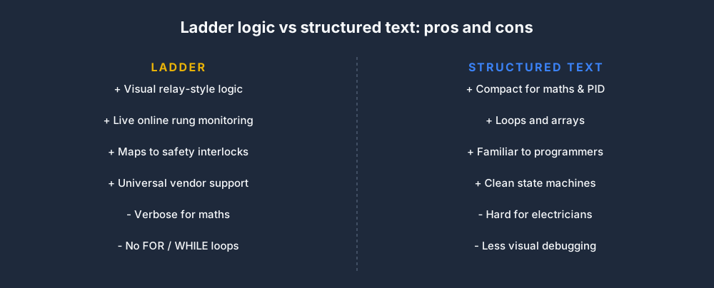
Pros and cons of ladder logic versus structured text as a first PLC language

Discrete Machine Control

Starting and stopping motors, controlling conveyors, opening valves on a pushbutton press — these are binary (on/off) operations that map directly to relay logic. Ladder is the natural language.

Safety Interlock Logic

Safety standards like IEC 62061 and EN ISO 13849 assume relay-style logic for defining safety functions. Ladder's contact/coil model maps cleanly to the logic requirements in a safety manual.

Maintenance and Troubleshooting

In the field, a maintenance technician can open a laptop, go online with the PLC, and watch contacts light up in real time. The visual feedback of ladder online mode is invaluable for fault-finding.

Vendor Familiarity

Allen-Bradley RSLogix/Studio 5000 users, Siemens TIA Portal users, and most other major vendor environments prioritise ladder. If you are targeting a specific vendor ecosystem, ladder is the safe choice.
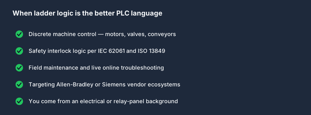
Checklist of when ladder logic is the better PLC language

Use Cases Where Structured Text Wins

Mathematical Computation

Expressing a PID algorithm, a linear interpolation, or a recipe calculation in ladder requires dozens of rungs and function blocks. In structured text it is ten lines. For any program with significant maths, ST is clearer and less error-prone.

Loop Processing

IEC 61131-3 forbids FOR and WHILE loops in ladder. If you need to iterate over an array of 100 setpoints, structured text is your only option.

Data Manipulation

Sorting arrays, parsing strings, building state machines with complex condition evaluation — all of these are verbose and fragile in ladder and clean in structured text.

Integration with Higher-Level Systems

If your PLC is doing JSON parsing, protocol conversion, or database queries (not common but increasingly relevant in edge computing applications), structured text is closer to familiar territory.
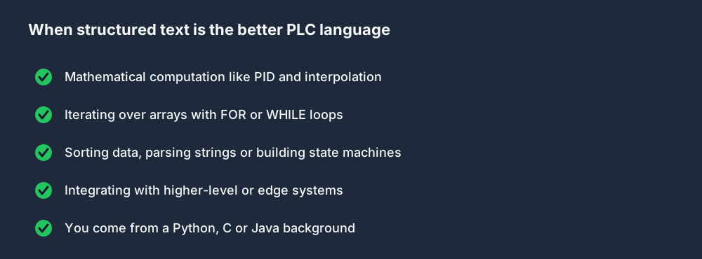
Checklist of when structured text is the better PLC language

Which to Learn First: A Decision Tree

For any individual task, the choice usually falls out of one question — what does the task mainly need?
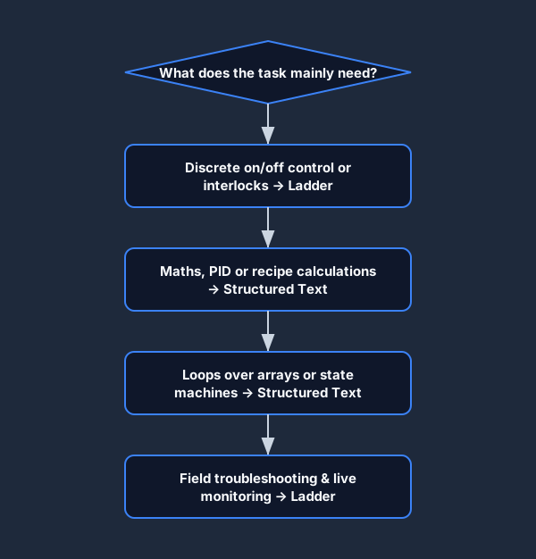
Flowchart for choosing between ladder logic and structured text for a task

For your first language, your background is the deciding factor:

  • You have an electrical background → Start with ladder. The relay metaphor will click immediately.
  • You have a software background → Start with structured text. You will write fluent code in a day. Then learn ladder so you can read existing programs in industry.
  • You want to get hired quickly → Learn ladder first. Most job listings in North America, Australia, and Europe specify ladder.
  • You are targeting process industries (oil and gas, water treatment, chemicals) → Learn both. Process programmers routinely use function block diagram and structured text for control loops and ladder for discrete interlocks.
  • You want to use a simulator to practice → The PLC Simulator supports both languages. Start with the Ladder Logic Basics lesson then progress to the Structured Text Intro lesson.

IEC 61131-3 and the Other Three Languages

IEC 61131-3 defines five languages. Besides LD and ST:

  • Function Block Diagram (FBD) — graphical blocks wired with signal lines; popular for analogue and PID; common in process industries.
  • Sequential Function Chart (SFC) — step-and-transition diagrams for sequential machines; excellent for complex sequences.
  • Instruction List (IL) — deprecated in the 2013 revision; looks like assembly. Avoid for new projects.

Most programmers eventually add FBD for PID loops and analogue processing. SFC is powerful for multi-step sequences. You do not need IL.

Read PLC Dialects Compared: IEC 61131-3 vs Allen-Bradley vs Siemens to understand how these standard languages are implemented differently across vendors.

Practical Next Steps

  1. Write a motor start/stop in ladder — see Seal-In Rungs in Ladder Logic: The Complete Guide.
  2. Re-implement the same logic in structured text.
  3. Compare them side by side. Notice what ladder makes obvious (the flow of logic) and what structured text makes obvious (the conditions and assignments).
  4. Progress to timers: Timers in PLC Programming: TON, TOF, TP Explained.

Both languages are in the same IEC 61131-3 standard and run on the same CPU inside the PLC. Your program can mix them: use ladder for the discrete interlocks, structured text for the maths, FBD for the PID loops. That is exactly what production programs look like.


Practice this yourself in the simulator — 3 scenarios free. No install. No credit card. Write real ladder logic against a live machine model in your browser.

Try the simulator free →

ShareX / TwitterLinkedIn

From reading to running logic

Practice this yourself in the simulator

Start with guided PLC practice in your browser. No install and no credit card required.

Start practising free

Continue learning

Related field notes

All articles
ladder logic
beginner

How to Read Ladder Logic (Step by Step for Beginners)

Learn to read ladder logic diagrams: rails, rungs, contacts, coils, timer and counter blocks. Step-by-step guide with real examples for complete beginners.

9 min read
ladder logic
fundamentals

Seal-In Rungs in Ladder Logic: The Complete Guide

A seal-in rung keeps a coil latched after the momentary start signal drops. Learn how to build reliable seal-in circuits with stop, overload, and E-stop protection.

8 min read
dialects
allen bradley

PLC Dialects Compared: IEC 61131-3 vs Allen-Bradley vs Siemens

IEC 61131-3, Allen-Bradley RSLogix/Studio 5000, and Siemens TIA Portal each use different syntax and naming conventions. Compare addressing, data types, timers, and more.

10 min read

Software evaluation field guide

Ladder logic versus Structured Text: implementation, evidence and troubleshooting

Direct answer

Ladder logic versus Structured Text becomes useful when it connects the control problem, data complexity, diagnostic audience, installed platform, standards and maintenance ownership with equivalent tags, state, instructions and outputs through the same scan and machine acceptance behavior, then proves one interlock, timer, calculation and state sequence expressed and tested in both languages under normal, boundary, fault and recovery conditions. The objective is a repeatable engineering or learning result, not merely activity inside a page or tool.

This guide is written for pLC learners and teams deciding which IEC language best expresses discrete control, sequences, calculations, data handling and maintainable diagnostics. The intended result is specific: the reader can choose by problem structure and team support, then prove equivalent behavior with the same I/O, timing, fault and restart tests.

System map / 02

Six concepts that control the result

Treat these as connected checkpoints. Each checkpoint has an expected state, an observable state and a boundary to the next part of the system. That structure prevents a software indication from being mistaken for physical proof.

NODE 01observable

Define the operating contract

the control problem, data complexity, diagnostic audience, installed platform, standards and maintenance ownership. For Ladder Logic and Structured Text selection, record the initial condition, actor, requested change, observable result and stopping condition before selecting a tool or implementation.

NODE 02observable

Map the evidence path

equivalent tags, state, instructions and outputs through the same scan and machine acceptance behavior. Separate request, internal state, output or service, physical or user-visible result and independent feedback so each boundary can be inspected.

NODE 03observable

Prove normal operation

one interlock, timer, calculation and state sequence expressed and tested in both languages. Run more than one cycle from a known state and retain the values, timings or artifacts that demonstrate repeatability.

NODE 04observable

Exercise a boundary case

evaluation order, loops, array limits, edge state, retentive data, restart and online diagnosis. Choose minimum, maximum, simultaneous, delayed or restart conditions that reveal assumptions hidden by the happy path.

NODE 05observable

Diagnose a controlled fault

a translation, type, priority, state or output-ownership mismatch. Preserve the first symptom, divide the system at a measurable boundary and change one condition only after predicting the result.

NODE 06observable

Transfer and hand over

the selected implementation reviewed and tested in the target environment by its maintainers. Restore normal state, remove temporary changes, repeat affected checks and document which claims remain limited to the learning environment.

Procedure / 03

A six-step practice and commissioning workflow

Run the steps in order the first time. Later, the same structure becomes a diagnostic loop: define the expected condition, observe the boundary, interpret the difference and choose one proving action.

  1. 01

    Write the acceptance case

    Convert the control problem, data complexity, diagnostic audience, installed platform, standards and maintenance ownership into initial conditions, one stimulus and observable pass criteria.

    Evidence: Another person can repeat the case without guessing the intended result.

    Avoid: Using page completion or an animation as the acceptance criterion.

  2. 02

    Build the map

    Document equivalent tags, state, instructions and outputs through the same scan and machine acceptance behavior and name who owns each state or decision.

    Evidence: Every request and result has a source, destination and useful inspection point.

    Avoid: Using the same value as command, status and independent feedback.

  3. 03

    Run the baseline

    Apply one interlock, timer, calculation and state sequence expressed and tested in both languages from a clean start and record the expected evidence.

    Evidence: Repeated runs produce the same bounded result.

    Avoid: Changing several parameters before a baseline exists.

  4. 04

    Challenge assumptions

    Test evaluation order, loops, array limits, edge state, retentive data, restart and online diagnosis without changing the acceptance contract.

    Evidence: Limits, timing and restart behavior reach defined states.

    Avoid: Testing only one ideal sequence.

  5. 05

    Isolate one failure

    Introduce or analyse a translation, type, priority, state or output-ownership mismatch and locate the first disagreement.

    Evidence: The proving action distinguishes the leading hypotheses.

    Avoid: Resetting, forcing or replacing before evidence is retained.

  6. 06

    Close the evidence loop

    Complete the selected implementation reviewed and tested in the target environment by its maintainers and repeat the affected regression cases.

    Evidence: An evaluation is complete when the same representative job is tested in each candidate and differences are recorded as evidence rather than inferred from feature labels.

    Avoid: Treating an acknowledged message or one successful rerun as handover.

Diagnostic matrix / 04

Symptoms, proving points and next actions

The table is a reasoning aid, not a parts-replacement chart. Preserve the initial symptom, inspect the named boundary and use the interpretation to choose the next controlled test. Site safety procedures and equipment manuals remain authoritative.

Diagnostic symptoms, inspection points, interpretations and next actions for Ladder logic versus Structured Text: implementation, evidence and troubleshooting
Observed symptomInspectInterpretationNext proving action
The expected result is unclearRequirement, initial state, actor, stimulus, units and pass conditionThe evaluator, instructor and technical buyer may be solving different versions of the task.Rewrite one observable acceptance case before continuing.
Internal state changes but the outcome does notRequest, final owner, output or service boundary and independent feedbackA software or interface indication proves intent at one layer, not the complete outcome.Trace the first boundary after the changing state.
Normal case passes but an edge case failsLimits, timing, simultaneous events, reset and restart assumptionsThe implementation contains a hidden assumption exposed by the changed condition.Add the failed boundary as a permanent regression case.
The failure disappears after resetOriginal symptom, histories, diagnostics, timestamps and active causeReset changed evidence or state without proving the initiating cause.Reproduce under a controlled condition and preserve pre/post-event data.
Simulator and target disagreeModel boundary, software version, task timing, I/O behavior, data types and configurationA learning model and the intended target do not share one of the recorded assumptions.Reduce the case and verify against current target documentation.
The result cannot be explainedPrediction, observation, proving action, alternative hypotheses and limitationsActivity occurred but the evidence is not yet transferable or reviewable.Have the learner defend the signal path and repeat a changed case.

Product evidence / 05

What the browser practice can actually demonstrate

The public product surface exposes runnable examples, capability boundaries, pricing context and test-harness behavior that can be checked before a purchasing decision.

Where simulation stops

Language choice does not by itself make code safe, portable or maintainable; exact syntax, execution and supported features vary by platform.

Commissioning notebook / 06

Six cases that turn the concepts into evidence

Use these as written briefs rather than click-through instructions. For every case, state the expected condition before acting, retain the first useful observation and explain why the final result proves the requirement. A different program or component choice can still be correct when it produces the same bounded behavior and evidence.

Case 01

predict → observe → prove

Prove define the operating contract

Engineering context. the control problem, data complexity, diagnostic audience, installed platform, standards and maintenance ownership. For Ladder Logic and Structured Text selection, record the initial condition, actor, requested change, observable result and stopping condition before selecting a tool or implementation. Begin with a written normal condition and identify which request, state, physical result or communication value will provide independent confirmation. Do not begin by changing the configuration; the initial state is part of the evidence and should remain reproducible.

Controlled setup. Use the “Write the acceptance case” stage of the workflow: convert the control problem, data complexity, diagnostic audience, installed platform, standards and maintenance ownership into initial conditions, one stimulus and observable pass criteria. The acceptance record should show this result: another person can repeat the case without guessing the intended result. Record initial conditions, the exact stimulus and the observation point so another learner can repeat the case without relying on your memory.

Fault challenge. Introduce or analyse “The expected result is unclear” as one bounded deviation. Inspect requirement, initial state, actor, stimulus, units and pass condition The working interpretation is that the evaluator, instructor and technical buyer may be solving different versions of the task. The next proving action is to rewrite one observable acceptance case before continuing. Change only one condition before observing the result, and preserve timestamps or measurements where timing matters.

Review and recovery. The most common trap here is using page completion or an animation as the acceptance criterion. After restoring the cause, repeat the normal case and at least one stop, timeout, disconnect or restart boundary relevant to this topic. Remove temporary forces and bypasses, return the model to a known state and retain the evidence that both operation and recovery are deliberate.

Explain it aloud: What should I learn first about Ladder Logic and Structured Text selection? A defensible short answer is: Start with the operating contract and evidence path: the control problem, data complexity, diagnostic audience, installed platform, standards and maintenance ownership, followed by equivalent tags, state, instructions and outputs through the same scan and machine acceptance behavior. Add advanced features only after the baseline is predictable.

Case 02

predict → observe → prove

Prove map the evidence path

Engineering context. equivalent tags, state, instructions and outputs through the same scan and machine acceptance behavior. Separate request, internal state, output or service, physical or user-visible result and independent feedback so each boundary can be inspected. Begin with a written normal condition and identify which request, state, physical result or communication value will provide independent confirmation. Do not begin by changing the configuration; the initial state is part of the evidence and should remain reproducible.

Controlled setup. Use the “Build the map” stage of the workflow: document equivalent tags, state, instructions and outputs through the same scan and machine acceptance behavior and name who owns each state or decision. The acceptance record should show this result: every request and result has a source, destination and useful inspection point. Record initial conditions, the exact stimulus and the observation point so another learner can repeat the case without relying on your memory.

Fault challenge. Introduce or analyse “Internal state changes but the outcome does not” as one bounded deviation. Inspect request, final owner, output or service boundary and independent feedback The working interpretation is that a software or interface indication proves intent at one layer, not the complete outcome. The next proving action is to trace the first boundary after the changing state. Change only one condition before observing the result, and preserve timestamps or measurements where timing matters.

Review and recovery. The most common trap here is using the same value as command, status and independent feedback. After restoring the cause, repeat the normal case and at least one stop, timeout, disconnect or restart boundary relevant to this topic. Remove temporary forces and bypasses, return the model to a known state and retain the evidence that both operation and recovery are deliberate.

Explain it aloud: How do I practise Ladder Logic and Structured Text selection effectively? A defensible short answer is: Use short cases with known initial conditions, a written prediction, one action and an observable result. Then alter a boundary or fault and explain why the evidence changed.

Case 03

predict → observe → prove

Prove prove normal operation

Engineering context. one interlock, timer, calculation and state sequence expressed and tested in both languages. Run more than one cycle from a known state and retain the values, timings or artifacts that demonstrate repeatability. Begin with a written normal condition and identify which request, state, physical result or communication value will provide independent confirmation. Do not begin by changing the configuration; the initial state is part of the evidence and should remain reproducible.

Controlled setup. Use the “Run the baseline” stage of the workflow: apply one interlock, timer, calculation and state sequence expressed and tested in both languages from a clean start and record the expected evidence. The acceptance record should show this result: repeated runs produce the same bounded result. Record initial conditions, the exact stimulus and the observation point so another learner can repeat the case without relying on your memory.

Fault challenge. Introduce or analyse “Normal case passes but an edge case fails” as one bounded deviation. Inspect limits, timing, simultaneous events, reset and restart assumptions The working interpretation is that the implementation contains a hidden assumption exposed by the changed condition. The next proving action is to add the failed boundary as a permanent regression case. Change only one condition before observing the result, and preserve timestamps or measurements where timing matters.

Review and recovery. The most common trap here is changing several parameters before a baseline exists. After restoring the cause, repeat the normal case and at least one stop, timeout, disconnect or restart boundary relevant to this topic. Remove temporary forces and bypasses, return the model to a known state and retain the evidence that both operation and recovery are deliberate.

Explain it aloud: What counts as proof of competence? A defensible short answer is: A repeatable artifact or system result plus an explanation of the signal path is stronger than time spent, screenshots or a copied answer. Physical competence requires separate supervised evidence.

Case 04

predict → observe → prove

Prove exercise a boundary case

Engineering context. evaluation order, loops, array limits, edge state, retentive data, restart and online diagnosis. Choose minimum, maximum, simultaneous, delayed or restart conditions that reveal assumptions hidden by the happy path. Begin with a written normal condition and identify which request, state, physical result or communication value will provide independent confirmation. Do not begin by changing the configuration; the initial state is part of the evidence and should remain reproducible.

Controlled setup. Use the “Challenge assumptions” stage of the workflow: test evaluation order, loops, array limits, edge state, retentive data, restart and online diagnosis without changing the acceptance contract. The acceptance record should show this result: limits, timing and restart behavior reach defined states. Record initial conditions, the exact stimulus and the observation point so another learner can repeat the case without relying on your memory.

Fault challenge. Introduce or analyse “The failure disappears after reset” as one bounded deviation. Inspect original symptom, histories, diagnostics, timestamps and active cause The working interpretation is that reset changed evidence or state without proving the initiating cause. The next proving action is to reproduce under a controlled condition and preserve pre/post-event data. Change only one condition before observing the result, and preserve timestamps or measurements where timing matters.

Review and recovery. The most common trap here is testing only one ideal sequence. After restoring the cause, repeat the normal case and at least one stop, timeout, disconnect or restart boundary relevant to this topic. Remove temporary forces and bypasses, return the model to a known state and retain the evidence that both operation and recovery are deliberate.

Explain it aloud: Why test faults and restart behavior? A defensible short answer is: Because a translation, type, priority, state or output-ownership mismatch or evaluation order, loops, array limits, edge state, retentive data, restart and online diagnosis can expose assumptions that never appear during ideal startup and steady operation.

Case 05

predict → observe → prove

Prove diagnose a controlled fault

Engineering context. a translation, type, priority, state or output-ownership mismatch. Preserve the first symptom, divide the system at a measurable boundary and change one condition only after predicting the result. Begin with a written normal condition and identify which request, state, physical result or communication value will provide independent confirmation. Do not begin by changing the configuration; the initial state is part of the evidence and should remain reproducible.

Controlled setup. Use the “Isolate one failure” stage of the workflow: introduce or analyse a translation, type, priority, state or output-ownership mismatch and locate the first disagreement. The acceptance record should show this result: the proving action distinguishes the leading hypotheses. Record initial conditions, the exact stimulus and the observation point so another learner can repeat the case without relying on your memory.

Fault challenge. Introduce or analyse “Simulator and target disagree” as one bounded deviation. Inspect model boundary, software version, task timing, I/O behavior, data types and configuration The working interpretation is that a learning model and the intended target do not share one of the recorded assumptions. The next proving action is to reduce the case and verify against current target documentation. Change only one condition before observing the result, and preserve timestamps or measurements where timing matters.

Review and recovery. The most common trap here is resetting, forcing or replacing before evidence is retained. After restoring the cause, repeat the normal case and at least one stop, timeout, disconnect or restart boundary relevant to this topic. Remove temporary forces and bypasses, return the model to a known state and retain the evidence that both operation and recovery are deliberate.

Explain it aloud: Can browser practice replace official software or hardware? A defensible short answer is: No. It can build concepts and diagnostic reasoning. Exact firmware, I/O electrical behavior, networking, safety and commissioning require current official tools, documentation and target equipment.

Case 06

predict → observe → prove

Prove transfer and hand over

Engineering context. the selected implementation reviewed and tested in the target environment by its maintainers. Restore normal state, remove temporary changes, repeat affected checks and document which claims remain limited to the learning environment. Begin with a written normal condition and identify which request, state, physical result or communication value will provide independent confirmation. Do not begin by changing the configuration; the initial state is part of the evidence and should remain reproducible.

Controlled setup. Use the “Close the evidence loop” stage of the workflow: complete the selected implementation reviewed and tested in the target environment by its maintainers and repeat the affected regression cases. The acceptance record should show this result: an evaluation is complete when the same representative job is tested in each candidate and differences are recorded as evidence rather than inferred from feature labels. Record initial conditions, the exact stimulus and the observation point so another learner can repeat the case without relying on your memory.

Fault challenge. Introduce or analyse “The result cannot be explained” as one bounded deviation. Inspect prediction, observation, proving action, alternative hypotheses and limitations The working interpretation is that activity occurred but the evidence is not yet transferable or reviewable. The next proving action is to have the learner defend the signal path and repeat a changed case. Change only one condition before observing the result, and preserve timestamps or measurements where timing matters.

Review and recovery. The most common trap here is treating an acknowledged message or one successful rerun as handover. After restoring the cause, repeat the normal case and at least one stop, timeout, disconnect or restart boundary relevant to this topic. Remove temporary forces and bypasses, return the model to a known state and retain the evidence that both operation and recovery are deliberate.

Explain it aloud: How should progress be documented? A defensible short answer is: Keep the requirement, initial state, program or configuration, observed values, fault hypothesis, proving action, recovery result and a concise limitations statement.

Answer surface / 07

Questions people ask about Ladder logic versus Structured Text

These concise answers define the operating, training and product boundaries most often missed in broad summaries. The full workflow and diagnostic table above provide the evidence behind them.

What should I learn first about Ladder Logic and Structured Text selection?

Start with the operating contract and evidence path: the control problem, data complexity, diagnostic audience, installed platform, standards and maintenance ownership, followed by equivalent tags, state, instructions and outputs through the same scan and machine acceptance behavior. Add advanced features only after the baseline is predictable.

How do I practise Ladder Logic and Structured Text selection effectively?

Use short cases with known initial conditions, a written prediction, one action and an observable result. Then alter a boundary or fault and explain why the evidence changed.

What counts as proof of competence?

A repeatable artifact or system result plus an explanation of the signal path is stronger than time spent, screenshots or a copied answer. Physical competence requires separate supervised evidence.

Why test faults and restart behavior?

Because a translation, type, priority, state or output-ownership mismatch or evaluation order, loops, array limits, edge state, retentive data, restart and online diagnosis can expose assumptions that never appear during ideal startup and steady operation.

Can browser practice replace official software or hardware?

No. It can build concepts and diagnostic reasoning. Exact firmware, I/O electrical behavior, networking, safety and commissioning require current official tools, documentation and target equipment.

How should progress be documented?

Keep the requirement, initial state, program or configuration, observed values, fault hypothesis, proving action, recovery result and a concise limitations statement.

What should I do when the answer differs from a guide?

Check assumptions, version, units and initial state first. Reduce the case, compare one boundary at a time and prefer current primary documentation for target-specific behavior.

When is a Ladder Logic and Structured Text selection exercise finished?

An evaluation is complete when the same representative job is tested in each candidate and differences are recorded as evidence rather than inferred from feature labels.