PLC Simulator
Robot Simulator · Live

Program a robot in your browser — free

Practise URScript on a simulated UR-style six-axis arm—or program a SCARA—run pick-and-place with live physics, and learn frames, TCP, I/O, the gripper, and cobot safety with auto-graded lessons, from zero. No install, no robot, no vendor license. Play free in your browser; go Pro for the full course and a certificate.

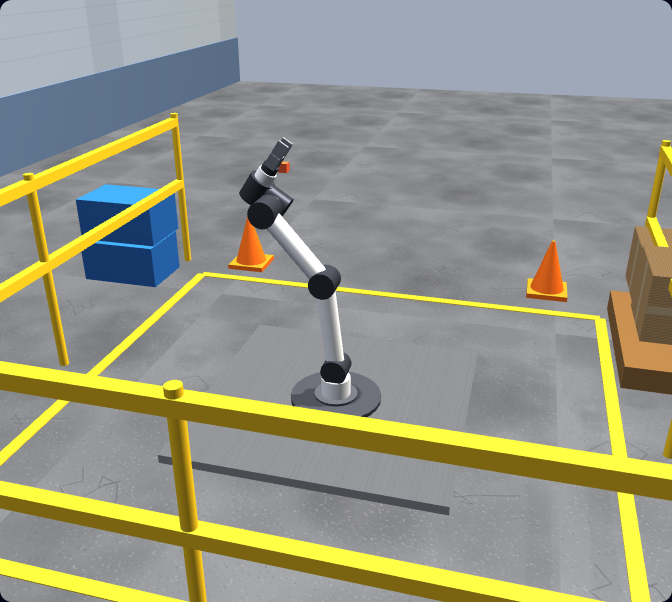
A UR-style six-axis robot arm standing in a 3D factory cell in the browser-based robot simulator, with a parts table, safety railing and pallet.
A UR-style six-axis arm in a 3D factory cell. You write the URScript; the simulator solves the kinematics and runs it under physics.
Real robot programming simulator footage

See this exact skill in the working simulator.

Watch the real browser product respond to the task on this page, then try the same practical workflow yourself. No slides, concept mockups, install, or credit card.

Try this in the browser
Robot Programming Simulator — Code a Real Pick-and-Place Cycle

Recognize the complete robot cell

From robot geometry to safe, repeatable production motion

The strongest robot-programming skills connect code to tooling, fixtures, coordinate frames, safety systems and commissioning practice. These six views show that full context.

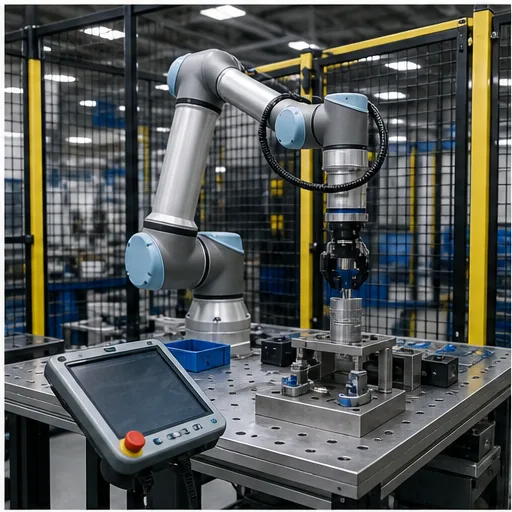
Six-axis collaborative robot in a guarded industrial training cell with a teach pendant and work fixtures
01A complete robot cell combines the manipulator, end effector, fixtures, controller, safeguarding and operator interface—not just the arm model.
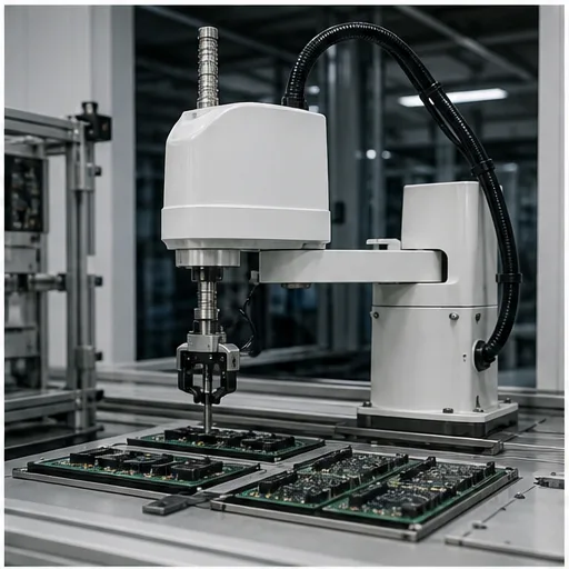
SCARA industrial robot performing top-down pick and place over electronic assemblies
02SCARA geometry is optimized for fast planar assembly and handling; its motion constraints differ from a six-axis articulated arm.
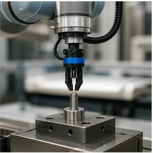
Robot gripper tool center point being aligned to a fixed calibration reference pin
03TCP calibration defines the controlled point on the tool. A wrong TCP can turn apparently correct waypoints into inaccurate or unsafe motion.
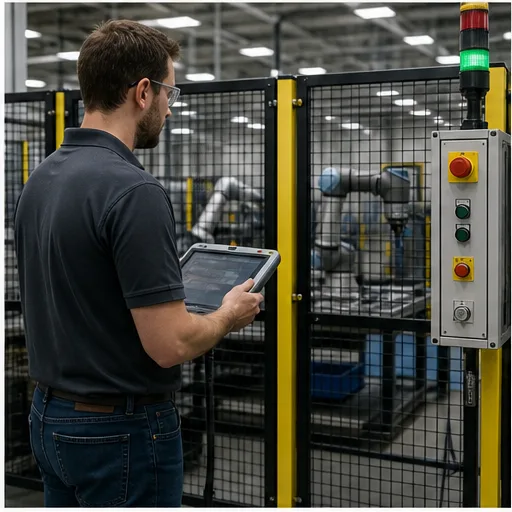
Automation technician checking robot cell guarding, emergency stops and safety status from outside the fence
04Robot programming is inseparable from risk assessment and safeguarding. Simulation can teach concepts but cannot validate a physical cell.
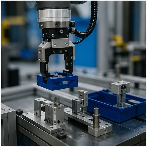
Industrial robot gripper transferring a blue component between accurate pick and place fixtures
05A successful handling cycle needs reachable poses, reliable grasp state, clearance and fixtures that constrain the part repeatably.
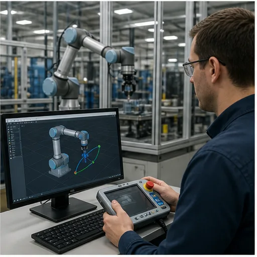
Robot programmer reviewing simulated waypoints on a workstation beside a guarded physical robot cell
06Offline practice helps form a motion plan; real deployment still requires controller-specific verification, controlled-speed testing and safety validation.

What it is

A live, browser-based robot programming simulator

A robot programming simulator lets you write the code that drives an industrial robot arm and watch it run — without owning the robot, installing heavyweight offline-programming software, or risking a real machine while you are still learning. You program the motion, the simulator solves the kinematics and physics, and you see exactly what the arm would do. Ours is live now and runs entirely in a browser tab.

You program a UR-style six-axis arm using URScript syntax relevant to Universal Robots controllers. You write movej and movel moves, set digital outputs, open and close a gripper, and build a full pick-and-place cycle. There is also a 4-axis SCARA — the fast top-down arm used for high-speed pick-and-place and assembly. The URScript interpreter, the arm, the gripper, and the parts on the table all run together in a single browser tab, under physics. It is the same approach that made our PLC simulator work: practise the real skill, in the browser, free to start.

A complete robot work cell in the simulator: a six-axis arm, a parts table with pick and place locations, a pallet, and a safety fence around the cellA top-down robot work cell: a central robot, an infeed conveyor, a pick fixture, a place pad, all enclosed by a safety fence.safety fenceconveyorpickRrobotplace
A full work cell in the browser — arm, parts table, pick and place stations, pallet, and a safety fence — the environment your URScript runs inside.

FANUC search intent

Does this replace FANUC classes or teach FANUC DCS?

FANUC robot programming

No. The live simulator currently teaches a UR-style arm and SCARA rather than a FANUC controller emulator. Joint versus linear motion, frames, TCP, waypoints, I/O and safe sequencing transfer conceptually, while FANUC pendant navigation, TP syntax and controller setup require FANUC-specific training. Use the FANUC robot programming guide for that vendor path.

FANUC DCS

Dual Check Safety is a FANUC safety function family used to monitor configured robot and tool limits. This product does not configure or validate DCS. Treat browser safety exercises as conceptual preparation only; risk assessment, safety-system design and validation belong to qualified people following the applicable manufacturer instructions and standards.

What it simulates

The robot geometries you actually meet on a line

Most browser “robot simulators” show a single articulated arm and stop there. The four configurations below cover the overwhelming majority of industrial automation you will program — and we model the kinematics of each so you feel how the same task changes when the geometry changes.

UR-style six-axis articulated robot arm with joints J1 to J6 and a gripper TCP, the main robot in the browser robot simulatorA six-axis articulated robot arm with a base and a two-finger gripper, its six rotary joints labelled J1 through J6.J1J2J3J4J5J6TCP
Six-axis articulated arm (live). The UR-style cobot you program in real URScript — six rotary joints, full reach, the workhorse of flexible automation.
Four-axis SCARA robot geometry with two rotary joints, a vertical Z axis and a rotating tool, for fast top-down pick-and-place in the robot simulatorA SCARA robot with two horizontal rotary links, a vertical Z prismatic axis, and a wrist, with the J1, J2, Z and wrist joints labelled.J1link 1J2link 2wristZ
4-axis SCARA (live). The fast, stiff, top-down arm built for high-speed pick-and-place and assembly — program it and feel how it differs from the six-axis.
Delta parallel robot with three arms and a shared end-effector platform for very high-speed pick-and-place, a robot geometry covered in the simulator curriculumA delta parallel robot: a fixed top plate with three motors driving three arms down to a small moving platform that carries the tool.fixed base platetool
Delta / parallel robot. The spider-leg parallel robot used for extreme-speed packaging and sorting — understand why its parallel kinematics behave so differently.
Cartesian gantry robot with three linear X Y Z axes moving a tool over a work area, a robot geometry explained in the browser robot simulatorA Cartesian gantry robot with three orthogonal linear axes — X across the bridge, Y along the rails, and Z up and down on the tool carriage.YXZ
Cartesian gantry. Three linear axes over a work area for palletising, dispensing, and large-format handling — the simplest geometry to reason about in straight X, Y, Z.

The six-axis arm and the SCARA are live and programmable now; the delta and Cartesian configurations are part of the wider curriculum so you understand the full landscape of industrial robot geometries, not just one.

How it works

Jog, write URScript, run, grade

1

Jog the arm

Move the arm in joint space and in Cartesian space to feel how it reaches, find your poses, and understand base vs tool frames and where the TCP sits — exactly as you would jog a real robot with a teach pendant.

2

Write real URScript

Type actual UR commands in the editor — movej, movel, movep, set_digital_out, gripper control, waypoints, variables, and loops. The interpreter understands the real language, not a simplified stand-in.

3

Run it under physics

The simulator solves the inverse kinematics for each target pose, plans a timed trajectory, and the arm tracks it under simulated dynamics. Grab a part and it follows the tool; a collision or an over-force contact is detected and surfaced.

4

Your program is graded

Each task defines success — part placed at B within tolerance, no collision, under the cycle-time budget, within the cobot force limit. Your program runs and is checked against those goals, with specific feedback on what to fix.

Real code

Practise recognizable URScript motion commands

No drag-blocks-only toy and no invented pseudo-language. A first pick-and-place program in the simulator looks like this. The command family is relevant to a physical Universal Robots controller, but controller version, installation data and safety configuration still matter:

# Pick a part at A, place it at B
set_tcp(p[0,0,0.15,0,0,0])        # tool centre point: 150 mm gripper
set_payload(0.8)                   # 0.8 kg part in the gripper

movej(home_q, a=1.4, v=1.0)        # joint move to a safe home pose
movel(pick_approach, a=1.2, v=0.3) # linear move above the pick
movel(pick, a=0.5, v=0.1)          # straight down onto the part
set_digital_out(0, True)           # close gripper
sleep(0.4)

movel(pick_approach, a=1.2, v=0.3) # lift straight up
movel(place, a=1.2, v=0.25)        # linear move to place B
set_digital_out(0, False)          # open gripper
movej(home_q, a=1.4, v=1.0)        # return home

The simulator parses this, solves the inverse kinematics for each target pose, plans the joint trajectory, and runs it under physics. movej moves fast through joint space; movel keeps the tool on a straight Cartesian line — the distinction every UR programmer has to learn, shown live.

How URScript becomes robot motion: parse the movej and movel commands, solve inverse kinematics for each pose, plan a timed joint trajectory, then run it under physics in the simulatorThree lines of URScript — movej, movel and set_digital_out — each mapped by an arrow to the corresponding motion on the robot arm.program.urpmovej(p1)movel(p2)set_digital_out(0,True)
From URScript to motion: parse → inverse kinematics per pose → trajectory planning → physics-tracked run. This is the pipeline the simulator runs every time you press Run.

What you’ll learn

From first jog to a graded pick-and-place cell

The course takes you from never having touched a robot to programming a working, collision-free pick-and-place cell — every lesson graded against a real goal.

Frames & TCP

Move the arm in joint space and in Cartesian space; understand base vs tool frames and how the tool centre point is defined.

movej vs movel

When each move type is right, how movep holds tool speed, and how acceleration and velocity change the motion.

I/O & gripper

Read and set digital signals; open and close a gripper to actually pick something up and put it down.

Pick-and-place A→B

The core skill: approach, grasp, lift, traverse, place, release — the backbone of real cobot work.

Waypoints & blends

Chain waypoints with blend radii for smooth, fast cycles instead of stop-start motion.

Payload & accuracy

Configure payload and TCP and see how they change reach, accuracy, and safe speed.

Protective-stop safety

Cobot protective stops: trigger and avoid over-force contacts; respect safety planes and speed limits.

SCARA programming

Program the 4-axis SCARA for fast top-down pick-and-place and assembly, and feel how it differs from the six-axis arm.

The pick-and-place cycle taught in the robot simulator: approach, grasp the part, lift, traverse to place B, lower, and release the gripperA repeating pick-and-place cycle around a loop: approach, close gripper, lift, traverse, place, open gripper.1Approach2Close3Lift4Traverse5Place6OpenLOOP
The pick-and-place cycle — approach, grasp, lift, traverse, place, release — the backbone of cobot work.
Collaborative robot safety in the simulator: a cobot inside a safety zone with reduced speed and a protective stop triggered by an over-force contactA collaborative robot surrounded by concentric speed-and-separation monitoring zones, with a protective-stop indicator when a person enters the inner zone.warningreduced speedstopPROTECTIVESTOP
Cobot safety — speed zones and force-limited protective stops, modelled so you build safe habits before real hardware.

Skills that transfer

What transfers to a real Universal Robots arm

Because you practise URScript syntax, the motion vocabulary and programming habits are useful preparation for a physical UR controller and PolyScope. They are not a substitute for the target controller manual, supervised commissioning or validation; the underlying articulated-arm concepts also need translation when you change brands.

movej versus movel in the robot simulator: a fast curved joint-space move compared with a straight-line Cartesian tool move between the same two posesTwo tool paths between the same two points: a curved joint move (movej) in cyan and a straight linear move (movel) in amber.ABmovej — joint arcmovel — straight line
movej takes a fast curved path through joint space; movel keeps the tool on a straight Cartesian line — the same decision every UR programmer makes.
Learned hereOn a real UR / PolyScope
URScript movej / movel / movepComparable commands in a Script node or .script program; verify the controller-version manual
TCP & payload configurationInstallation-specific TCP and payload setup must be measured and verified on the robot
Base vs tool frames / featuresFeature planes and coordinate frames in PolyScope
Waypoints & blend radiusWaypoint nodes with blend in the program tree
Digital I/O & gripper controlset_digital_out and tool I/O on the real controller
Protective stop / force limitsSafety configuration and force-mode behaviour

Reviewed August 7, 2026 · Primary references

Motion-command descriptions are checked against the Universal Robots Script Directory. Robot-system and safeguarding context follows the OSHA Technical Manual chapter on industrial robot systems. Product capability statements describe this browser training environment, not a manufacturer-certified emulator or safety-validation tool.

Pricing

Free to play, Pro to master

Start with the free lessons — write URScript and run the simulated arm in your browser at no cost, no card. Go Pro to unlock the full graded course end-to-end and earn a verifiable Robot Programming certificate of completion. Same login as our PLC simulator.

The robot programming path in the simulator: free lessons, then the full Pro course, leading to a verifiable robot programming certificate of completionA progression from lessons, through three completed checkmarks, to a certificate seal — learn then certify.lessonspass graded taskscertificate
Free lessons → full Pro course → a verifiable certificate you can share on a CV or LinkedIn.

Keep exploring

More robot programming resources

Questions

Robot simulator FAQ

Yes — you can start for free. Open it in your browser and work through the free lessons, writing real URScript and running a simulated robot arm at no cost and with no card. A Pro subscription unlocks the full graded course end-to-end and a verifiable certificate of completion. So the simulator is free to start, and Pro is there when you want the complete curriculum and proof of completion.

Program a robot in your browser.

No install. No robot. No vendor license. Real URScript on a UR-style arm and a SCARA — free to play, graded from zero.

Robot simulation field guide

Robot simulator: frames, motion, I/O and commissioning evidence

Direct answer

A robot simulator should teach more than point-to-point animation. Useful practice connects coordinate frames, motion type, tool and payload assumptions, program flow, PLC handshakes, collision awareness, faults and restart behavior to an observable workcell task.

This guide is written for pLC learners adding robotics, junior robot programmers and controls engineers practising cell handshakes before supervised work on target equipment. The intended result is specific: the learner can explain a pick-and-place cycle, distinguish joint and linear motion, map request/busy/complete/fault signals and recover from a stopped sequence without skipping ownership checks.

System map / 02

Six concepts that control the result

Treat these as connected checkpoints. Each checkpoint has an expected state, an observable state and a boundary to the next part of the system. That structure prevents a software indication from being mistaken for physical proof.

NODE 01observable

Frames

Base, tool and work-object frames define how positions are interpreted; a correct numeric pose in the wrong frame is still wrong.

NODE 02observable

Motion type

Joint motion prioritizes axis travel while linear motion constrains the tool path; each has different process and clearance implications.

NODE 03observable

Tool and payload

Tool center point and payload assumptions affect path, accuracy, dynamics and controller limits.

NODE 04observable

Program state

Approach, pick, retreat, transfer, place and recovery should be explicit states with guarded transitions.

NODE 05observable

PLC handshake

Requests, busy, complete, fault and reset need one owner and a tested startup/restart contract.

NODE 06observable

Cell safety

Robot motion permission depends on validated safety architecture outside an ordinary PLC program.

Procedure / 03

A six-step practice and commissioning workflow

Run the steps in order the first time. Later, the same structure becomes a diagnostic loop: define the expected condition, observe the boundary, interpret the difference and choose one proving action.

  1. 01

    Define the task

    Describe part source, destination, orientation, process condition and cycle boundary.

    Evidence: Success can be observed in the cell.

    Avoid: Teaching motion commands without a job.

  2. 02

    Set frames

    Establish base, tool and work reference assumptions.

    Evidence: Every taught point has a named coordinate context.

    Avoid: Compensating for a bad frame with points.

  3. 03

    Teach safe geometry

    Add approach, process and retreat points with clearance.

    Evidence: The intended path avoids fixtures in the model.

    Avoid: Driving directly between process points.

  4. 04

    Write state logic

    Sequence motion, gripper and checks with timeouts.

    Evidence: Each state has entry, completion and failure behavior.

    Avoid: Using fixed delays for every physical event.

  5. 05

    Connect the PLC

    Implement request, permission, busy, done and fault ownership.

    Evidence: Both sides agree during normal and abnormal cases.

    Avoid: Sharing one bit for multiple meanings.

  6. 06

    Test recovery

    Stop at each phase and define the restart decision.

    Evidence: No part is dropped, duplicated or processed twice.

    Avoid: Jumping to home without checking payload and position.

Diagnostic matrix / 04

Symptoms, proving points and next actions

The table is a reasoning aid, not a parts-replacement chart. Preserve the initial symptom, inspect the named boundary and use the interpretation to choose the next controlled test. Site safety procedures and equipment manuals remain authoritative.

Diagnostic symptoms, inspection points, interpretations and next actions for Robot simulator: frames, motion, I/O and commissioning evidence
Observed symptomInspectInterpretationNext proving action
Robot moves to wrong placeFrame selection, taught point, tool center point and offsetsThe path may be internally consistent in the wrong coordinate system.Display the active frames.
Path clips equipmentApproach geometry, linear segment, tool shape and fixture stateEndpoint checks do not prove path clearance.Inspect the complete trajectory.
PLC waits foreverRequest, busy, done, fault, reset and sequence state on both sidesHandshake ownership or transition timing disagrees.Trend all handshake bits.
Gripper misses partTool pose, part presence, grip output, delay/feedback and payload stateMotion completion does not prove acquisition.Require independent part-held evidence.
Restart duplicates actionLast completed state, retained bits, part location and acknowledgementThe sequence cannot infer physical truth from software state alone.Reconcile cell state before transition.
Cycle time unstableMotion blend, wait conditions, PLC timing and process variabilityThe robot may be waiting for external state rather than moving slowly.Separate motion and wait durations.

Product evidence / 05

What the browser practice can actually demonstrate

Browser robot and 3D cell exercises expose programmed motion, workpieces, PLC-connected state, scenario tasks and visible workcell response without requiring a local robot package.

Where simulation stops

The simulator is not an offline programming or safety-validation package for a specific robot. Reach, singularity, collision, payload, timing, safety zones and controller behavior must be verified in the manufacturer environment and real cell.

Commissioning notebook / 06

Six cases that turn the concepts into evidence

Use these as written briefs rather than click-through instructions. For every case, state the expected condition before acting, retain the first useful observation and explain why the final result proves the requirement. A different program or component choice can still be correct when it produces the same bounded behavior and evidence.

Case 01

predict → observe → prove

Prove frames

Engineering context. Base, tool and work-object frames define how positions are interpreted; a correct numeric pose in the wrong frame is still wrong. Begin with a written normal condition and identify which request, state, physical result or communication value will provide independent confirmation. Do not begin by changing the configuration; the initial state is part of the evidence and should remain reproducible.

Controlled setup. Use the “Define the task” stage of the workflow: describe part source, destination, orientation, process condition and cycle boundary. The acceptance record should show this result: success can be observed in the cell. Record initial conditions, the exact stimulus and the observation point so another learner can repeat the case without relying on your memory.

Fault challenge. Introduce or analyse “Robot moves to wrong place” as one bounded deviation. Inspect frame selection, taught point, tool center point and offsets The working interpretation is that the path may be internally consistent in the wrong coordinate system. The next proving action is to display the active frames. Change only one condition before observing the result, and preserve timestamps or measurements where timing matters.

Review and recovery. The most common trap here is teaching motion commands without a job. After restoring the cause, repeat the normal case and at least one stop, timeout, disconnect or restart boundary relevant to this topic. Remove temporary forces and bypasses, return the model to a known state and retain the evidence that both operation and recovery are deliberate.

Explain it aloud: Can I learn robot programming in a browser? A defensible short answer is: You can learn frames, motion concepts, program structure and PLC handshakes. Exact vendor programming requires the relevant controller or official environment.

Case 02

predict → observe → prove

Prove motion type

Engineering context. Joint motion prioritizes axis travel while linear motion constrains the tool path; each has different process and clearance implications. Begin with a written normal condition and identify which request, state, physical result or communication value will provide independent confirmation. Do not begin by changing the configuration; the initial state is part of the evidence and should remain reproducible.

Controlled setup. Use the “Set frames” stage of the workflow: establish base, tool and work reference assumptions. The acceptance record should show this result: every taught point has a named coordinate context. Record initial conditions, the exact stimulus and the observation point so another learner can repeat the case without relying on your memory.

Fault challenge. Introduce or analyse “Path clips equipment” as one bounded deviation. Inspect approach geometry, linear segment, tool shape and fixture state The working interpretation is that endpoint checks do not prove path clearance. The next proving action is to inspect the complete trajectory. Change only one condition before observing the result, and preserve timestamps or measurements where timing matters.

Review and recovery. The most common trap here is compensating for a bad frame with points. After restoring the cause, repeat the normal case and at least one stop, timeout, disconnect or restart boundary relevant to this topic. Remove temporary forces and bypasses, return the model to a known state and retain the evidence that both operation and recovery are deliberate.

Explain it aloud: What is the difference between joint and linear motion? A defensible short answer is: Joint motion coordinates axes toward a target; linear motion constrains the tool center point along a straight Cartesian path.

Case 03

predict → observe → prove

Prove tool and payload

Engineering context. Tool center point and payload assumptions affect path, accuracy, dynamics and controller limits. Begin with a written normal condition and identify which request, state, physical result or communication value will provide independent confirmation. Do not begin by changing the configuration; the initial state is part of the evidence and should remain reproducible.

Controlled setup. Use the “Teach safe geometry” stage of the workflow: add approach, process and retreat points with clearance. The acceptance record should show this result: the intended path avoids fixtures in the model. Record initial conditions, the exact stimulus and the observation point so another learner can repeat the case without relying on your memory.

Fault challenge. Introduce or analyse “PLC waits forever” as one bounded deviation. Inspect request, busy, done, fault, reset and sequence state on both sides The working interpretation is that handshake ownership or transition timing disagrees. The next proving action is to trend all handshake bits. Change only one condition before observing the result, and preserve timestamps or measurements where timing matters.

Review and recovery. The most common trap here is driving directly between process points. After restoring the cause, repeat the normal case and at least one stop, timeout, disconnect or restart boundary relevant to this topic. Remove temporary forces and bypasses, return the model to a known state and retain the evidence that both operation and recovery are deliberate.

Explain it aloud: What is a robot tool center point? A defensible short answer is: It is the coordinate frame attached to the working point of the tool, used to interpret poses and paths.

Case 04

predict → observe → prove

Prove program state

Engineering context. Approach, pick, retreat, transfer, place and recovery should be explicit states with guarded transitions. Begin with a written normal condition and identify which request, state, physical result or communication value will provide independent confirmation. Do not begin by changing the configuration; the initial state is part of the evidence and should remain reproducible.

Controlled setup. Use the “Write state logic” stage of the workflow: sequence motion, gripper and checks with timeouts. The acceptance record should show this result: each state has entry, completion and failure behavior. Record initial conditions, the exact stimulus and the observation point so another learner can repeat the case without relying on your memory.

Fault challenge. Introduce or analyse “Gripper misses part” as one bounded deviation. Inspect tool pose, part presence, grip output, delay/feedback and payload state The working interpretation is that motion completion does not prove acquisition. The next proving action is to require independent part-held evidence. Change only one condition before observing the result, and preserve timestamps or measurements where timing matters.

Review and recovery. The most common trap here is using fixed delays for every physical event. After restoring the cause, repeat the normal case and at least one stop, timeout, disconnect or restart boundary relevant to this topic. Remove temporary forces and bypasses, return the model to a known state and retain the evidence that both operation and recovery are deliberate.

Explain it aloud: How does a PLC communicate with a robot? A defensible short answer is: Cells commonly use mapped discrete or network data for requests, permissions, busy, completion, faults and data exchange.

Case 05

predict → observe → prove

Prove plc handshake

Engineering context. Requests, busy, complete, fault and reset need one owner and a tested startup/restart contract. Begin with a written normal condition and identify which request, state, physical result or communication value will provide independent confirmation. Do not begin by changing the configuration; the initial state is part of the evidence and should remain reproducible.

Controlled setup. Use the “Connect the PLC” stage of the workflow: implement request, permission, busy, done and fault ownership. The acceptance record should show this result: both sides agree during normal and abnormal cases. Record initial conditions, the exact stimulus and the observation point so another learner can repeat the case without relying on your memory.

Fault challenge. Introduce or analyse “Restart duplicates action” as one bounded deviation. Inspect last completed state, retained bits, part location and acknowledgement The working interpretation is that the sequence cannot infer physical truth from software state alone. The next proving action is to reconcile cell state before transition. Change only one condition before observing the result, and preserve timestamps or measurements where timing matters.

Review and recovery. The most common trap here is sharing one bit for multiple meanings. After restoring the cause, repeat the normal case and at least one stop, timeout, disconnect or restart boundary relevant to this topic. Remove temporary forces and bypasses, return the model to a known state and retain the evidence that both operation and recovery are deliberate.

Explain it aloud: Does a robot simulator detect every collision? A defensible short answer is: No. Collision results depend on model fidelity, tooling, fixtures, payload and controller behavior.

Case 06

predict → observe → prove

Prove cell safety

Engineering context. Robot motion permission depends on validated safety architecture outside an ordinary PLC program. Begin with a written normal condition and identify which request, state, physical result or communication value will provide independent confirmation. Do not begin by changing the configuration; the initial state is part of the evidence and should remain reproducible.

Controlled setup. Use the “Test recovery” stage of the workflow: stop at each phase and define the restart decision. The acceptance record should show this result: no part is dropped, duplicated or processed twice. Record initial conditions, the exact stimulus and the observation point so another learner can repeat the case without relying on your memory.

Fault challenge. Introduce or analyse “Cycle time unstable” as one bounded deviation. Inspect motion blend, wait conditions, PLC timing and process variability The working interpretation is that the robot may be waiting for external state rather than moving slowly. The next proving action is to separate motion and wait durations. Change only one condition before observing the result, and preserve timestamps or measurements where timing matters.

Review and recovery. The most common trap here is jumping to home without checking payload and position. After restoring the cause, repeat the normal case and at least one stop, timeout, disconnect or restart boundary relevant to this topic. Remove temporary forces and bypasses, return the model to a known state and retain the evidence that both operation and recovery are deliberate.

Explain it aloud: What should a beginner simulate first? A defensible short answer is: Use a pick-and-place with clear approach, grip, transfer, release and home states plus a simple PLC handshake.
Answer surface / 07

Questions people ask about Robot simulator

These concise answers define the operating, training and product boundaries most often missed in broad summaries. The full workflow and diagnostic table above provide the evidence behind them.

Can I learn robot programming in a browser?

You can learn frames, motion concepts, program structure and PLC handshakes. Exact vendor programming requires the relevant controller or official environment.

What is the difference between joint and linear motion?

Joint motion coordinates axes toward a target; linear motion constrains the tool center point along a straight Cartesian path.

What is a robot tool center point?

It is the coordinate frame attached to the working point of the tool, used to interpret poses and paths.

How does a PLC communicate with a robot?

Cells commonly use mapped discrete or network data for requests, permissions, busy, completion, faults and data exchange.

Does a robot simulator detect every collision?

No. Collision results depend on model fidelity, tooling, fixtures, payload and controller behavior.

What should a beginner simulate first?

Use a pick-and-place with clear approach, grip, transfer, release and home states plus a simple PLC handshake.
How should robot faults be reset?

Remove the cause, verify cell state and follow the exact controller and site procedure before issuing reset or restart.

Can simulation prove robot safety?

No. Robot and machine safety require risk assessment, validated functions, guarding and qualified commissioning.

Industrial robotics path

Progress from motion concepts to a complete cell sequence

Practise coordinates and commands, connect the robot handshake to PLC state, then validate safety and vendor-specific behavior in the correct tools.