Electrical-to-logic diagnosis
Follow a symptom from field input and address mapping through the PLC scan to the output and physical machine response.
Run an industrial maintenance training path across motors, drives, sensors, safety circuits, pumps and intermittent PLC faults—without reserving a hardware bench or stopping a production machine.
Fault-injection training model
Intermittent Double-Start Fault
Motor starters, VFDs, sensors, safety chains, pumps and conveyors
Dedicated wrong-address, stuck-input, timer, counter and scan-order faults
Live I/O, machine physics and ladder execution during diagnosis
Repeatable grading for normal operation, fault isolation and recovery
Evidence-led maintenance practice
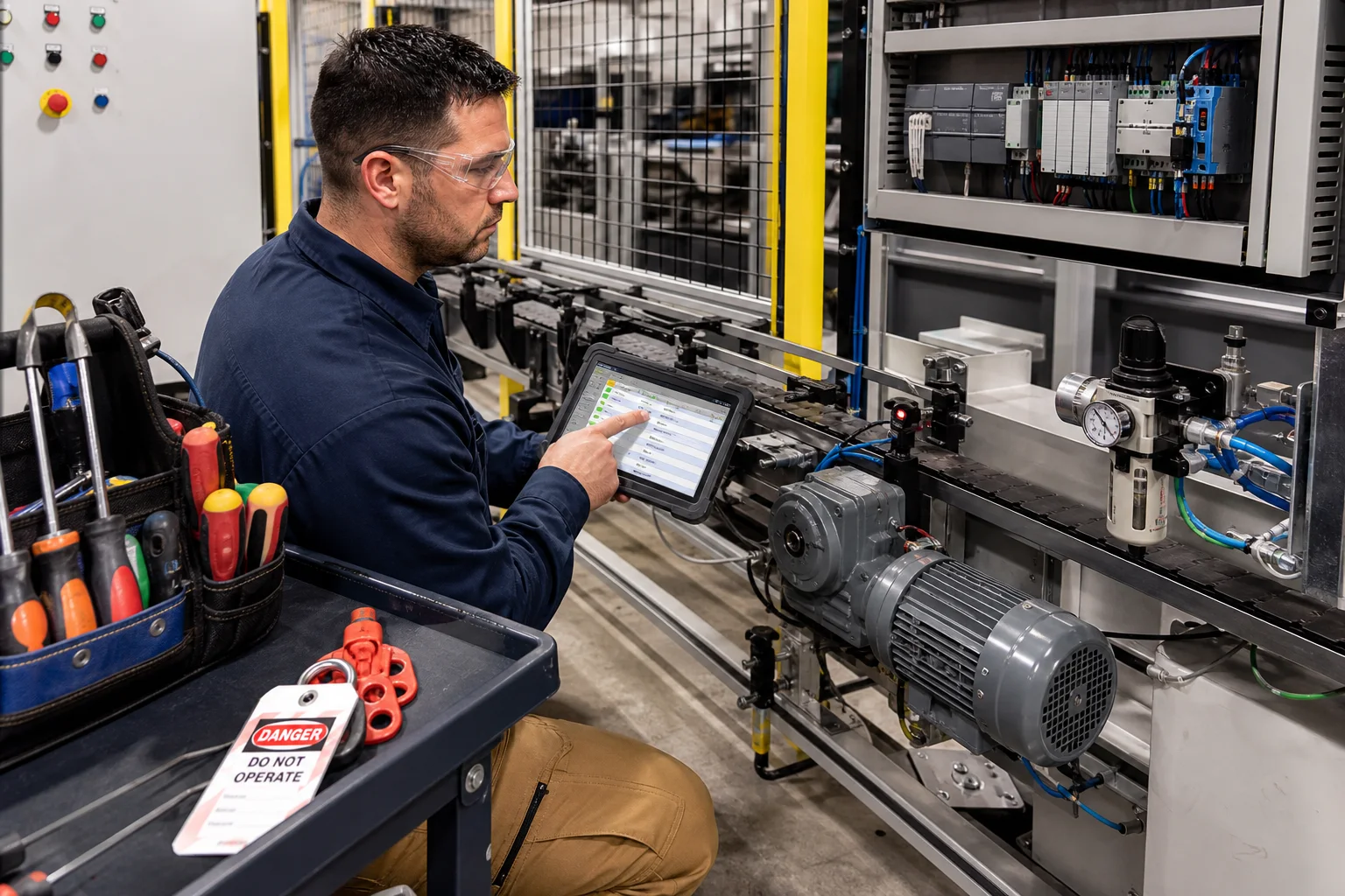
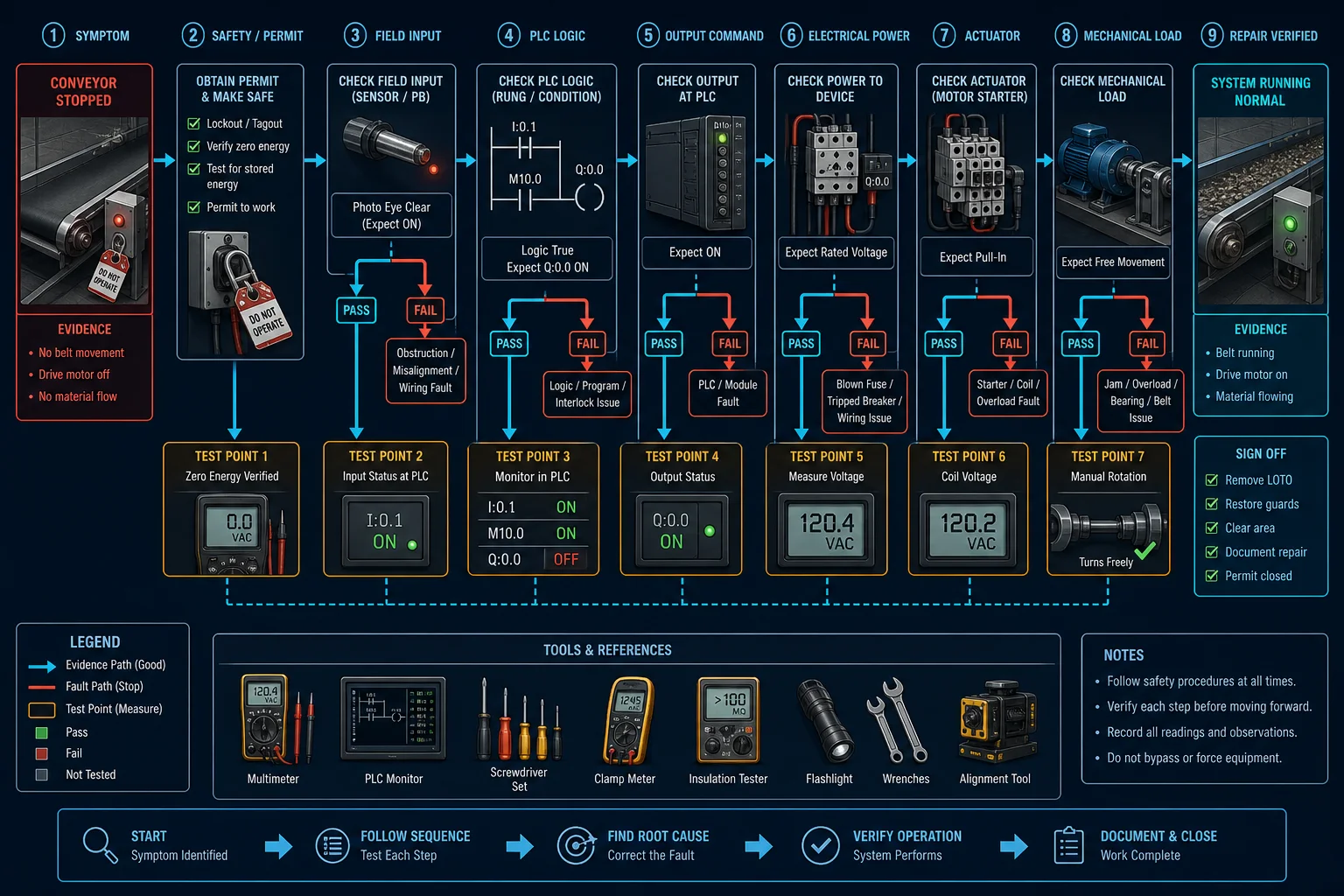
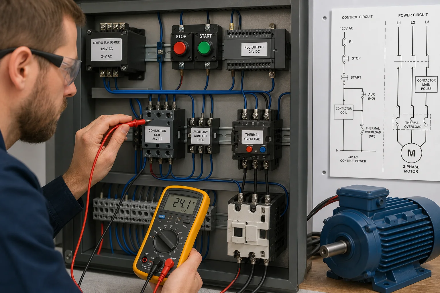
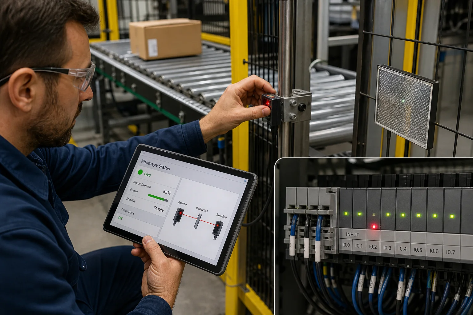
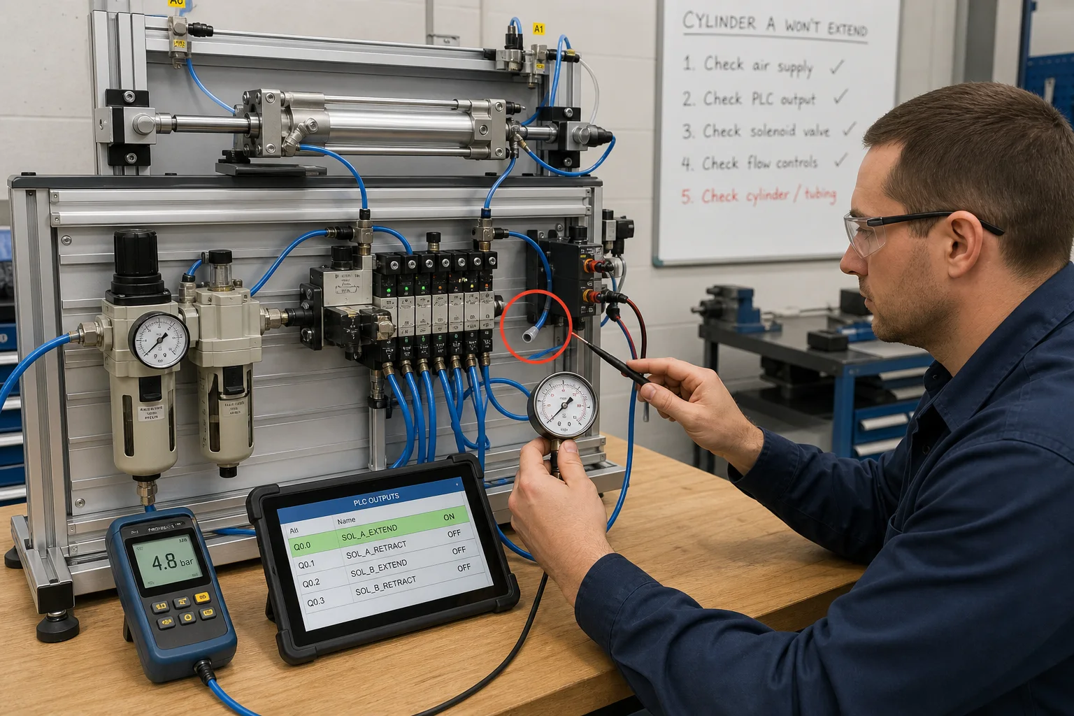
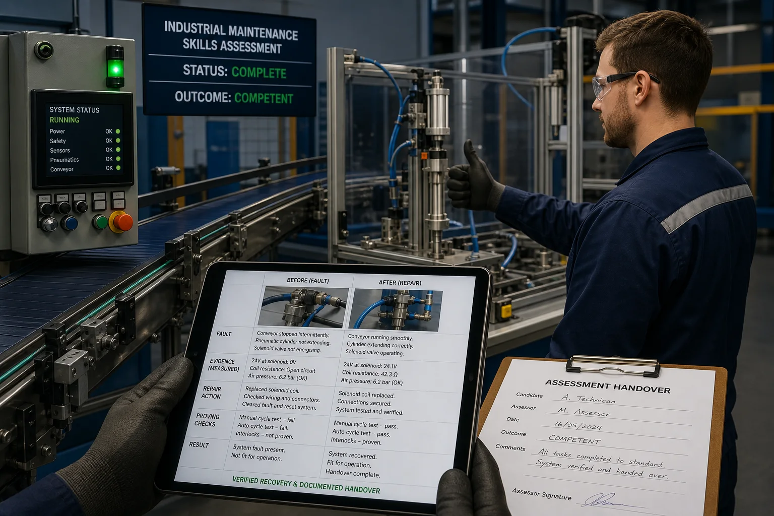
Industrial maintenance work crosses sensors, PLC logic, motor control, pneumatics and the physical load. These views show the diagnostic boundaries a learner must prove instead of guessing which part to replace.
Multi-craft controls coverage
The library concentrates on the controls layer of industrial maintenance: reading I/O, tracing ladder state, proving permissives, identifying timing and scan-order faults, and recovering equipment safely.
Follow a symptom from field input and address mapping through the PLC scan to the output and physical machine response.
Practise seal-in circuits, reversing interlocks, star-delta timing, VFD speed control and safe drive-fault reset.
Work with E-stop reset, two-hand control, light-curtain muting, guard and process permissives without touching live machinery.
Troubleshoot alternating pumps, level alarms, dosing, valves, temperature and other common plant utility patterns.
Industrial maintenance training guide
Good industrial maintenance training teaches a repeatable way to isolate faults across the entire control path. A learner should be able to explain the evidence, correct the cause, run the machine through normal and abnormal cases, and document what proved the repair.
Industrial maintenance training develops the skills used to keep production equipment safe, available and predictable.
A complete multi-craft programme can include mechanical power transmission, bearings, lubrication, hydraulics, pneumatics, electrical systems, instrumentation, PLCs, robotics and site safety. This online path deliberately concentrates on the controls portion: sensors and field signals, PLC execution, motor and drive commands, permissives, alarms, sequence state and fault recovery.
That boundary matters. A browser lab can build diagnostic reasoning and repeatable controls practice, but it cannot replace supervised work on site-specific energy isolation, live electrical equipment or mechanical systems.
Define the symptom, make the equipment safe, then divide the control path into testable boundaries rather than replacing the most suspicious component.
Start with one input controlling one output, then add memory, permissives, timing, analog signals, sequences and injected faults in that order.
The sequence reduces cognitive load because each new exercise preserves the signal-tracing method while adding one new idea. Beginners first learn what a normally open or normally closed instruction means in the context of a real switch. They then build start/stop seal-in logic, interpret overload and E-stop conditions, use timers and counters, scale analog signals, and finally troubleshoot complete machines.
Advanced technicians can skip the guided build and move directly to diagnostic challenges, but they are graded against the same observable machine behavior and recovery requirements.
The lab should expose field state, PLC state and machine response at the same time so learners can compare the command with the evidence.
For a motor starter, that means separating the start request, seal-in state, overload contact, PLC output, contactor coil and auxiliary feedback. For a VFD, it means distinguishing enable, run command, reference, trip state and safe reset. For a photoeye, it means comparing target presence, sensor output, input LED, mapped address and the consuming rung.
The fault library includes wrong addresses, stuck inputs, unsafe resets, timer behavior, counters, scan-order defects and intermittent sequences because those failures are difficult to learn from a static diagram alone.
A credible assessment records the diagnosis, corrective action, passing test cases and safe recovery—not only whether the final output turned on.
US labor data indicates strong demand in the related industrial machinery maintenance occupation group, although local roles and entry requirements vary.
The US Bureau of Labor Statistics projects 13% employment growth from 2024 to 2034 for industrial machinery mechanics, machinery maintenance workers and millwrights, with about 54,200 openings per year on average. PLC and automation skills are only one part of those roles, but they are directly relevant where technicians diagnose automated production equipment.
A platform completion certificate documents practice completed here; it is not an accredited credential or a substitute for an employer practical assessment. Learners seeking independent automation credentials can also review certification and training pathways from the International Society of Automation.
Scenario library
Diagnose an edge-dependent intermittent failure that appears only under a specific operating sequence.
Build and verify a latched motor circuit with E-stop, overload and auxiliary feedback.
Detect a drive trip and allow reset only after a deliberate safe recovery sequence.
Trace a healthy field signal mapped to the wrong PLC address and correct the logic fault.
Separate a frozen process signal from a logic error using live state and controlled tests.
Commission and recover a safety muting sequence with timing and reset constraints.
Training outcomes
Assignments can grade normal operation, unsafe demands, boundary conditions and recovery behavior against the same machine model.
Free planning resource · PDF + editable CSV
Use the included controls skills matrix, practical assessment rubric, sample report and 30/60/90-day training plan to turn scenario practice into a repeatable team programme.
Scope, stated plainly
The platform covers PLC, electrical-control and automation-maintenance practice. It does not teach mechanical drives, bearings, hydraulics, pneumatics, welding, HVAC service or statutory lockout procedures as complete disciplines, so it should complement—not replace—a multi-craft maintenance curriculum.
Related training solutions
Add hidden motor-control faults, multimeter evidence, scored diagnoses and team records.
Explore solutionMeasure troubleshooting and PLC-control competence with graded practical tasks.
Explore solutionFocus specifically on diagnosis, fault isolation and recovery practice.
Explore solutionPilot with your standards
Use the existing labs immediately, then map assignments and pass criteria to the equipment, failure modes and competencies your team owns.
Maintenance diagnostics field guide
Direct answer
Industrial maintenance training software is useful when it makes equipment behavior measurable. The learner should isolate a symptom, choose a safe test, identify the failed boundary and prove restoration across sensors, control power, PLC logic, starters, drives, pneumatics and process equipment.
This guide is written for industrial maintenance technicians, multi-skill apprentices, reliability teams and supervisors who need repeatable fault practice without risking production equipment. The intended result is specific: the technician can convert a broad complaint such as “the conveyor stopped” into a precise evidence trail that distinguishes command, permissive, feedback, electrical, mechanical and process failures.
Describe what failed, when it failed and what still works before assigning a cause. A precise symptom prevents the diagnosis from expanding into unrelated systems.
Identify electrical, pneumatic, hydraulic, gravity, thermal and stored mechanical energy before selecting any inspection or measurement.
Compare what the control system asked for with the independent evidence that the device or process actually responded.
Trace the path until expected and observed state first diverge; downstream alarms are often consequences rather than causes.
Choose the safest test that can distinguish the leading hypotheses, state the expected outcomes first and change one condition at a time.
After repair, restore protection, remove bypasses, repeat the failure case and document evidence that normal operation and stopping both work.
Record operator wording, time, operating mode, recent changes and the last known good cycle.
Evidence: A bounded symptom and timeline replace assumptions about the failed component.
Avoid: Translating “does not work” directly into a parts request.
Apply the employer procedure for shutdown, isolation, dissipation, lockout and verification.
Evidence: The approved energy-control state is established before exposure or continuity work.
Avoid: Assuming a stopped HMI animation means hazardous energy is controlled.
Verify supply, protection, mode, emergency chain, permissives and obvious physical obstruction.
Evidence: Each observation eliminates a branch of the fault tree.
Avoid: Resetting repeatedly without recording why the trip occurred.
Follow request, PLC decision, output, interface, actuator and feedback in order.
Evidence: The first mismatch defines the next measurement point.
Avoid: Jumping between software and mechanics without a signal path.
Correct the confirmed defect using approved parts, settings and workmanship.
Evidence: The measured failure condition is absent after repair.
Avoid: Changing multiple components and losing causal evidence.
Inspect, restore guards, clear personnel, test stop paths and run the original operating case.
Evidence: The machine completes the case and returns to a known state.
Avoid: Calling the job complete when the alarm clears.
| Observed symptom | Inspect | Interpretation | Next proving action |
|---|---|---|---|
| Contactor will not pull in | Control supply, fuse, stop chain, overload auxiliary, command and A1–A2 voltage | Voltage location separates an upstream open circuit from a failed coil or mechanical contactor problem. | Measure across the intended boundary with the correct meter mode. |
| VFD will not run | Ready state, STO, run source, speed reference, interlocks and active trip | A drive needs both a command and a valid reference under the selected ownership mode. | Prove source selection before changing parameters. |
| Sensor misses product | Target, alignment, contamination, supply, output indication, input LED and tag | The physical detection point may fail before the controller ever sees an input. | Compare device, module and software state during one controlled pass. |
| Cylinder is slow | Pressure, flow control, valve command, spool state, leakage, load and end feedback | Slow movement can be pneumatic, mechanical or command-duration related. | Separate commanded valve state from resulting pressure and motion. |
| Motor trips intermittently | Current trend, phase condition, load, starts per hour, cooling and trip history | The last trip code and pre-trip load are stronger evidence than a successful reset. | Reproduce only under controlled conditions and retain the trend. |
| Process value is implausible | Sensor range, loop current, wiring polarity, input configuration, scaling and quality | A valid numeric tag can still represent the wrong engineering value. | Inject known points and verify the entire measurement chain. |
Product evidence / 05
The product provides controlled logic, wiring, motor-control, VFD, sensor and process faults plus virtual measurements, live tags and behavioral grading. Known fault injection makes the diagnosis repeatable while hidden-fault assessments test independent reasoning.
Practical training requires equipment state, safe test selection, measurements, fault isolation and verified recovery. Watching a repair does not prove that the learner can diagnose a different failure.
They need enough programming knowledge to trace conditions, timers, latches, modes and sequence state. The goal is safe diagnosis first; program modification requires separate authority and change control.
Yes, when faults are physically and logically coherent and the learner must show evidence. Random error messages without a signal path teach guessing rather than diagnosis.
Record the symptom, operating state, observations, measurements, confirmed cause, correction, parts or settings changed and the functional tests completed before handover.
A repair can restore motion while leaving protection, interlocks or feedback ineffective. Functional proving must include stopping and abnormal response, not only production output.
No. Follow meter instructions and the employer procedure. The simulator blocks live continuity mode and uses voltage measurements for energized diagnostic practice.
Capture time-aligned command, permissive, output, feedback, alarm and process data around the event. Preserve the first deviation and avoid clearing history before review.
It can retain scenario and assessment evidence, but it cannot certify physical competence or replace an employer, college or accredited certification body.
Troubleshooting learning path
Establish the expected state, isolate the failed signal path, test one hypothesis and prove the repair under the original conditions.