Power + control together
Trace 400 V main power and 24 V control instead of learning each half in isolation.
A complete browser workbench for DOL, forward/reverse, jog, Hand/Off/Auto and star-delta circuits—with guided commissioning, recognizable components, live power paths and a virtual multimeter.
Responsive touch controls · momentary buttons work while held · safe training model
Quick answer: a motor-control simulator should show both the low-voltage decision circuit and the three-phase power path. This workbench combines recognizable starter hardware, live contacts, motor behavior, exact meter nodes, inserted faults and commissioning checks.


Recognize the circuit before you operate it
Use these component-level views to connect the schematic symbols to the power path, control decisions, interlocks, starting sequence and measurements you will make in the interactive workbench.
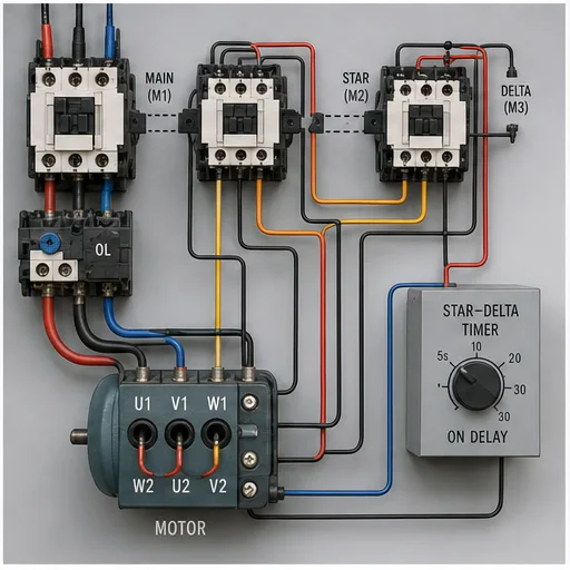
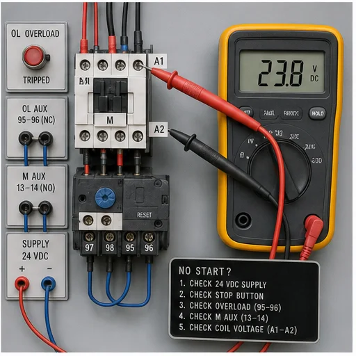
Use this page to understand the equipment, workflow and terminology. Sign in to the Pro path to operate the full physics model, complete commissioning evidence, inject faults and continue into a prepared PLC–HMI Sandbox project.
DOL three-wire starter
Foundation
Forward / reverse starter
Interlocking
Run / jog control
Machine motion
Hand / Off / Auto pump
Process demand
Star–delta sequence
Advanced
Watch the real browser product respond to the task on this page, then try the same practical workflow yourself. No slides, concept mockups, install, or credit card.
Try this in the browserFrom schematic to evidence
Every circuit ties the symbolic control idea to recognizable hardware, main-current behavior and the measurements used to prove what is actually wrong.
Trace 400 V main power and 24 V control instead of learning each half in isolation.
Coils, auxiliary contacts, main poles, latches and interlocks update as the circuit operates.
Choose exact nodes for voltage and continuity readings, including an explicit live-circuit safety block.
Control fuse, stop chain, coil, welded pole, overload, missing phase and failed interlock.
Direction, rpm, inrush, star current reduction, coast-down and load-side power respond over time.
Stop, overload, interlock, rotation and loaded-current checks complete only after demonstrated.
Shipped features · verified 15 July 2026
These are live product capabilities, not roadmap promises. Five guided circuit workbenches, the full meter model, inserted faults and evidence records are included in Pro.
DOL, forward/reverse, run/jog, Hand/Off/Auto pump control and open-transition star–delta
Recognizable isolator, contactor, overload relay, operator controls and induction motor
Three-phase power path and low-voltage control path with live conductor state
Coils, auxiliary contacts, main poles, latches and electrical/mechanical interlocks
Named red/black probe nodes for control voltage, line voltage and isolated continuity
Direction, rpm, inrush, star current reduction, transition and coast-down
Seven inserted faults across supply, stop chain, coil, poles, overload, phases and interlocks
Step-by-step actions, reasons, expected evidence and progressive hints for every circuit
Functional stop, overload, interlock, direction, transition and loaded-current proving checks
Visual field guide
The illustrations identify the physical devices, the symbolic circuit and the evidence a meter should find. The live workbench then changes the same paths and components as the circuit operates or fails.
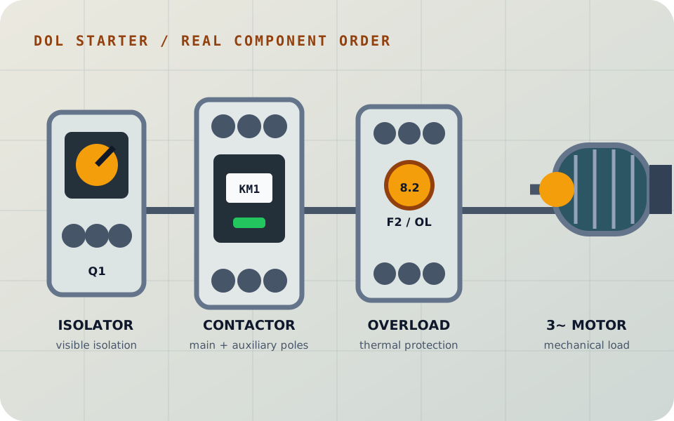
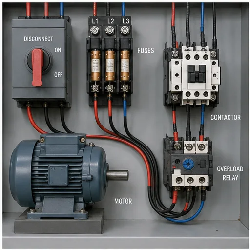
Hardware recognition
The isolator provides visible disconnection, the contactor switches the motor, the overload protects against sustained excess current and the motor converts the three-phase supply into mechanical motion.
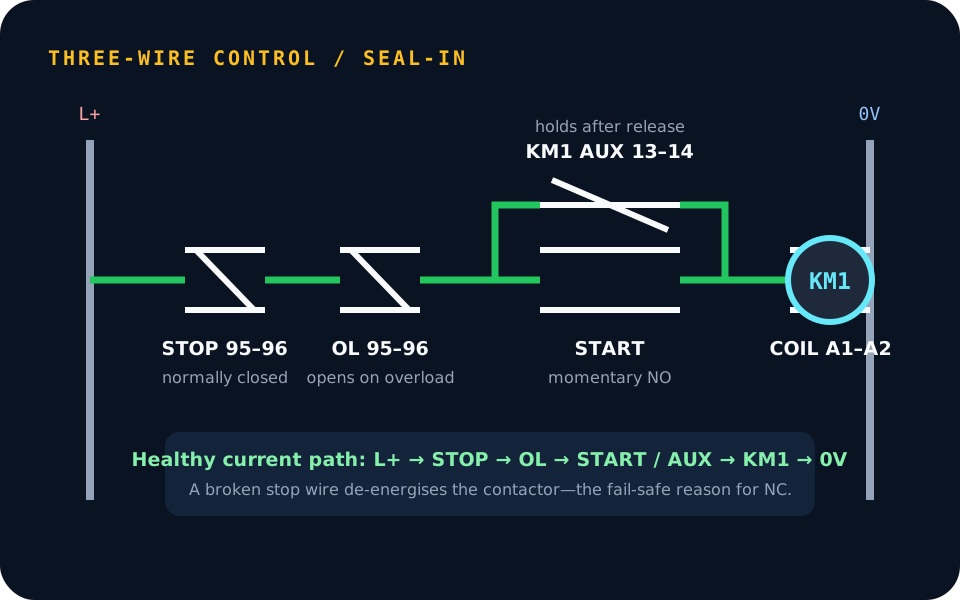
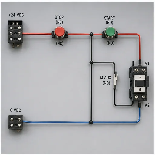
DOL control
START initially energises KM1. The contactor auxiliary contact then closes around START so the coil remains energised after release. STOP or overload opening breaks the same series path.
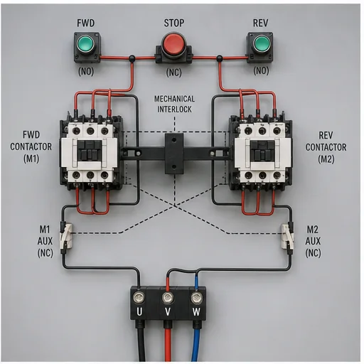
Reversing
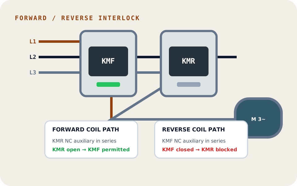
Reversal changes phase sequence. Electrical cross-interlocks and a mechanical interlock must prevent forward and reverse contactors from closing together and creating a phase-to-phase fault.
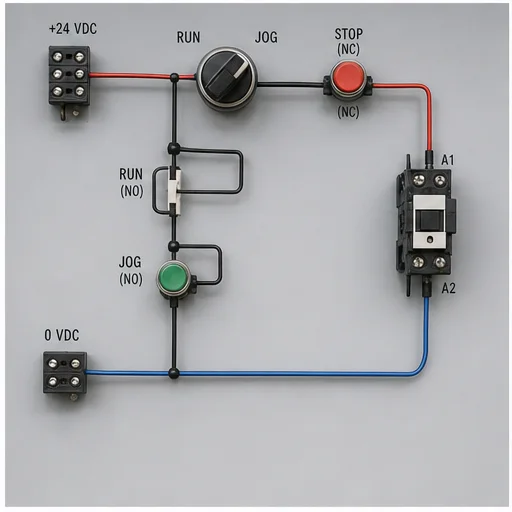
Operator control
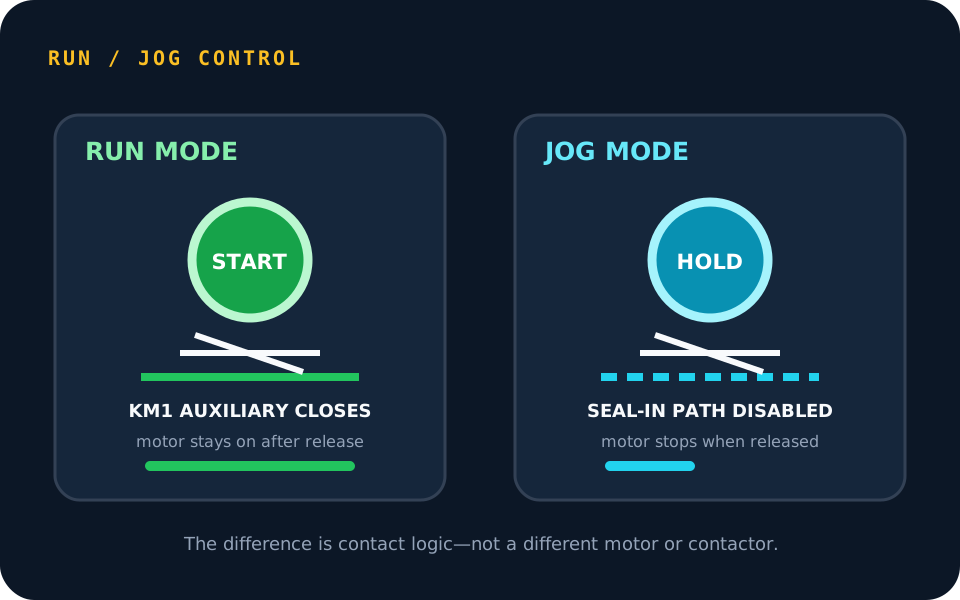
RUN uses the normal auxiliary seal-in path. JOG deliberately prevents latching, so the motor operates only while the jog command is held and stops when it is released.
Reduced-current starting
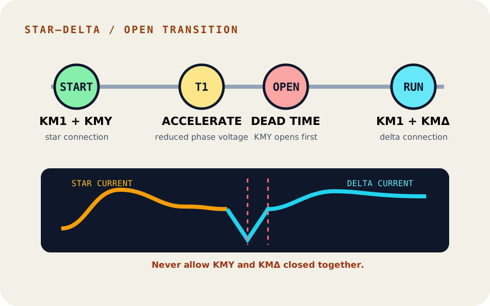
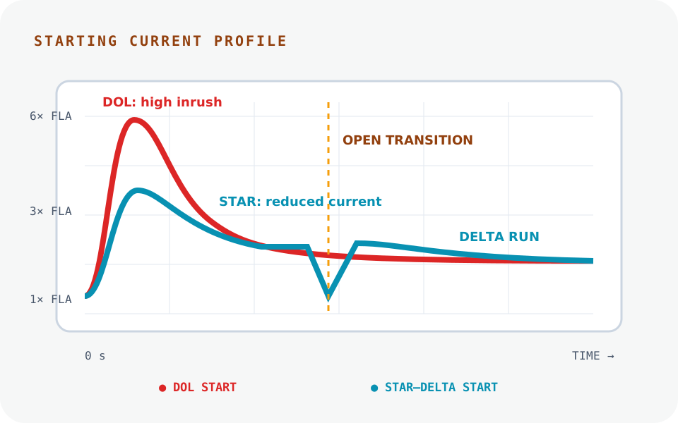
The main and star contactors start the motor with reduced winding voltage. Star then opens, a transition interval passes, and delta closes for normal running without overlapping the two configurations.
Electrical evidence
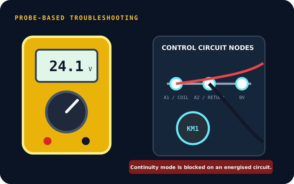
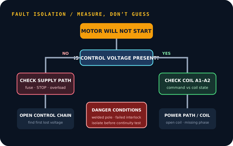
Voltage across A1–A2 proves whether the coil is being commanded. Measuring along the control chain locates the first point where voltage is lost instead of encouraging parts replacement by guesswork.
Motor behavior
DOL applies full line voltage immediately and produces the largest inrush. Star–delta reduces starting current but introduces sequencing, interlocking and transition requirements.
Troubleshooting
A structured path separates a missing control supply, an open stop chain, a commanded but failed coil and a closed contactor with missing main power. Dangerous welded-contact and interlock faults remain explicit.
Circuit library
The simulator does not present DOL, reversing, jog, Hand/Off/Auto and star–delta as interchangeable diagrams. It shows what changes in the hardware, control logic, power path and motor response.
| Circuit | Contactors | Defining control feature | Typical task |
|---|---|---|---|
| DOL three-wire | 1 | STOP, overload, START and seal-in auxiliary | Simple fixed-direction pumps, fans and conveyors |
| Forward / reverse | 2 | Cross-interlock, mechanical interlock and phase swap | Hoists, doors, traverses and reversible conveyors |
| Run / jog | 1 | Selectable maintained or momentary control path | Setup, positioning and maintenance movement |
| Hand / Off / Auto | 1 | Maintained local command, OFF override and automatic process demand | Pumps, fans and packaged process equipment |
| Star–delta | 3 | Main, star and delta sequence with open transition | Reduced-current starting of suitable six-lead motors |
The control circuit decides whether a coil is permitted to energise. Its series safety chain normally includes a control fuse, normally-closed STOP, normally-closed overload auxiliary, permissives or interlocks, then the command and coil return. Auxiliary contacts create holding or blocking logic.
The power circuit carries motor current through the isolator or breaker, contactor main poles and overload elements to the motor. The contactor coil can be correctly energised while the power circuit still has a missing phase, open pole or tripped overload.
Fault diagnosis
When a motor does not start, begin with the symptom and the approved schematic. Prove the expected control supply, follow voltage through the series chain, determine whether the coil is commanded, and only then move to the three-phase power path. The virtual meter uses named nodes so every reading has an electrical meaning.
Likely evidence
No control voltage anywhere downstream
Proving action
Measure supply first, then both sides of the fuse.
Likely evidence
Voltage enters the chain but does not reach START
Proving action
Find the first series contact with voltage on one side only.
Likely evidence
Correct voltage across A1–A2 but no contactor movement
Proving action
Isolate, then verify coil continuity and rating.
Likely evidence
One phase remains connected after the coil drops out
Proving action
Isolate and compare line-side and load-side pole state.
Likely evidence
Contactor closes but motor current and torque are abnormal
Proving action
Measure all three phase-to-phase paths and inspect the power chain.
Likely evidence
Forward and reverse can overlap
Proving action
Treat as dangerous; isolate and prove both electrical and mechanical interlocks.
Resistance and continuity functions apply a meter’s internal test source; they are not intended to be connected to an energised control circuit. The simulator forces isolation before continuity testing. For live diagnosis it provides voltage mode, named probe points and an explicit live-state warning—training the meter setup as part of the fault-finding method.
Functional proving
A tidy schematic is not proof of operation. The commissioning sheet only completes when the learner demonstrates the intended stop, protection, direction and loaded-current behavior in the simulated circuit.
Identify Q1, control protection, contactors, overload, operator devices and motor. Confirm the circuit is isolated before continuity work.
Check STOP and overload contacts are closed when healthy, then verify the coil path and auxiliary contact arrangement.
Close the isolator and use the intended momentary control. Observe coil, auxiliary and main-pole state rather than listening only for a click.
Prove STOP removes the command and the overload auxiliary drops the contactor. Confirm a broken safety-chain conductor fails to stop.
For reversing, confirm phase sequence and prove the opposite command is blocked electrically and mechanically while running.
Compare DOL inrush or the star–open–delta sequence. Confirm no star/delta contactor overlap occurs.
Check the simulated phase condition, current and stable running speed after acceleration. Investigate imbalance or overload evidence.
Insert a fault, locate it with defensible measurements, remove the cause and repeat the affected functional check.
Safety and scope
The browser lab can make relationships visible without exposing a learner to electrical energy. It can show why a normally-closed stop is fail-safe, why an overload auxiliary sits in the coil path, why reversing needs two forms of interlock and why the meter mode matters.
It cannot assess a person’s practical competence, prove absence of voltage on real equipment, select protection, verify fault level, determine conductor size or replace supervision and local procedures. Those boundaries are displayed because credible training should clarify what has and has not been proven.
Why not full 3D?
A 3D cabinet is useful for physical panel layout, reach, routing and assembly. It is weaker for understanding which auxiliary contact controls which coil, comparing two live branches or placing probes on named electrical nodes.
This simulator therefore uses realistic 2D hardware inside a schematic workspace, with live highlighting and motor animation. The learner can see the real component and the electrical relationship at the same time—even on a phone.
Continue the motor-control path
This page teaches the circuits with visible fault controls. The dedicated electrical troubleshooting simulator conceals the answer, counts meter and safety actions, scores the submitted diagnosis and saves an assessment record. Wiring, ladder logic and VFD practice remain linked as separate tasks.
Motor-control circuit field guide
Direct answer
A motor control circuit simulator should keep the control circuit, contactor state, overload protection, power poles, motor current and mechanical result coherent. The useful learning task is not merely energizing a coil: it is predicting named measurements, proving why the motor starts or stops and isolating one fault without unsafe bypasses.
This guide is written for electrical and automation learners practicing three-wire control, reversing, overload response, PLC interfaces and three-phase motor diagnosis. The intended result is specific: the learner can trace source through stop and permissive contacts to the coil, distinguish control from power behavior and prove the failed boundary with an appropriate voltage or isolated-continuity test.
Identify control voltage, reference conductor, protective device and where voltage should be present before and after each series condition.
Use a momentary start, normally closed stop and auxiliary seal-in contact while maintaining deliberate stop priority.
Separate coil energization, mechanical armature movement, auxiliary contacts and three power poles as related but individually observable states.
Interpret overload auxiliary state and trip cause without treating reset as removal of excessive current, phase loss or mechanical load.
Trace every phase from source through protection and contactor poles to the motor; a healthy control circuit cannot prove balanced power.
Use auxiliary, speed or process feedback to distinguish a software or coil command from actual rotation and useful machine work.
Mark source, return, stop chain, start branch, seal-in contact, coil and overload auxiliary.
Evidence: The expected current path is known before operation.
Avoid: Following wire color rather than node function.
State voltage to reference and voltage across key open and closed devices.
Evidence: Probe expectations are written before the meter is placed.
Avoid: Calling every zero-volt reading a fault.
Operate the circuit and observe coil, auxiliary, power-pole and motor state.
Evidence: The complete chain changes coherently and stop retains priority.
Avoid: Watching only the contactor animation.
Open a control condition, fail a pole, remove a phase or trip the overload.
Evidence: The original symptom and first changed evidence are preserved.
Avoid: Activating several faults simultaneously.
Use one approved measurement to decide whether the fault is upstream or downstream.
Evidence: Each reading eliminates at least one hypothesis.
Avoid: Using continuity on an energized model.
Remove the cause, restore protection and repeat start, running and stop cases.
Evidence: Balanced electrical and physical behavior returns without bypasses.
Avoid: Stopping after the coil pulls in.
| Observed symptom | Inspect | Interpretation | Next proving action |
|---|---|---|---|
| Coil never energizes | Control supply, stop chain, overload auxiliary, permissive, start path and coil voltage | The first point missing expected voltage locates the open branch. | Divide the series path at a named node. |
| Coil drops after Start is released | Auxiliary seal-in contact, parallel branch and mechanical contactor state | The momentary command works but maintained control is absent. | Prove voltage across the seal-in boundary. |
| Contactor pulls in, motor is idle | Line voltage, all power poles, overload path, phase balance and motor terminals | The control circuit succeeded while the power or load layer failed. | Measure phase-to-phase at approved boundaries. |
| Motor runs in one direction only | Reverse command path, electrical/mechanical interlock, second contactor and phase swap | One directional branch or power path is unavailable. | Compare forward and reverse states without defeating interlocks. |
| Overload trips repeatedly | Phase current, balance, setting, starts, cooling, voltage and mechanical load | The device may be correctly responding to thermal demand. | Record current and correct the cause before reset. |
| Motor starts unexpectedly after return | Maintained command, retentive software state, contactor state and restart policy | Control state may not require a new deliberate start. | Test power-return behavior as an explicit case. |
Product evidence / 05
The browser lab connects an interactive schematic, named multimeter nodes, contactor motion, overload state, phase condition, motor behavior and controlled faults. Safety-action scoring records whether the learner used an appropriate measurement sequence.
It teaches schematic reading, start-stop logic, contactor and overload behavior, multimeter interpretation, power-circuit tracing and fault isolation without exposing a learner to real energy.
It commonly uses momentary start and stop devices plus a contactor auxiliary seal-in contact so a deliberate stop opens the maintained coil path.
A failed power pole, missing phase, open overload path, disconnected motor or mechanical problem can exist downstream of a healthy coil circuit.
Use named nodes and a stated reference. The correct points depend on the schematic, expected state, meter category and approved site procedure.
No. Continuity belongs to an isolated and verified de-energized state under the applicable procedure and meter instructions.
Possible causes include excessive load, phase loss, voltage problems, repeated starts, poor cooling, incorrect setting or a motor defect. Preserve current and trip evidence.
Electrical and mechanical interlocks prevent forward and reverse contactors from being energized together; the exact circuit must also define stopping and direction-change policy.
No. It demonstrates learning-model reasoning only. Physical work requires employer authorization, safety training, tools, PPE decisions and supervised competence.
Motor, wiring and VFD path
Move from safe control wiring and contactors into VFD parameters, measurements, faults and PLC command paths.