Public guide
The indexed marketing page explains the equipment, terminology, workflow, features and product boundaries.
A dated source of truth for what the VFD/VSD commissioning and motor-control circuit simulators can do today. Every row identifies the shipped capability, product, access level, practical scope and a direct link to the working evidence.
Answer in one sentence: the platform currently ships 39 documented Pro drive and motor-control capabilities across 10 categories, including 23 VFD-specific and 13 motor-control-specific capabilities, while the public pages remain detailed technical guides.
39
Live capabilities
23
VFD / VSD
13
Motor control
10
Categories
Last technically verified: August 9, 2026
How to read this matrix
The indexed marketing page explains the equipment, terminology, workflow, features and product boundaries.
Every interactive job, measurement, fault, assessment and saved commissioning record requires an active Pro subscription.
Shipped feature register
The unfiltered table is rendered as the canonical inventory. Search and filters help evaluators isolate a task without hiding the complete list from the page source.
Showing 39 of 39 live capabilities
VFD / VSD · Wiring
L1/L2/L3, PE and U/V/W connections with isolation enforced before terminal changes.
VFD / VSD · Wiring
Run input/common plus AI1/analog common; the pump job uses a 4–20 mA reference.
VFD / VSD · Safety
Independent STO-A and STO-B paths must both be connected and healthy before torque is enabled.
VFD / VSD · Parameters
Rated voltage, frequency, current, speed and power are checked against each job sheet.
VFD / VSD · Parameters
A first-start job requires matched nameplate data, complete motor/STO wiring, safe energisation and motor ID before RUN is enabled.
VFD / VSD · Parameters
Minimum/maximum frequency, acceleration, deceleration, command source and reference source.
VFD / VSD · Control
Local setpoint, run/stop, direction proving and uncoupled bump-test workflow.
VFD / VSD · Control
Digital run command with separate speed-reference selection in the conveyor job.
VFD / VSD · Control
Live loop value, current-input selection and minimum-to-maximum frequency scaling in the pump job.
VFD / VSD · Control
Network command/reference behaviour and communication-oriented fan commissioning workflow.
VFD / VSD · Control
Maintained two-wire and latched three-wire run behavior, low-speed jog priority and forward/reverse operation.
VFD / VSD · Control
Keypad, 0–10 V, 4–20 mA, fieldbus, three preset speeds, motorized potentiometer and process PID references.
VFD / VSD · Physics
Ramp, coast, quick-stop and DC-brake responses plus flying-start capture on a rotating motor.
VFD / VSD · Physics
Low-speed torque response changes with scalar versus motor-model-based control while the same load remains connected.
VFD / VSD · Diagnostics
Current capping, prohibited frequency band and ramp/coast/hold-last fieldbus-loss behavior are observable in live evidence.
VFD / VSD · Diagnostics
Run, reverse, jog, quick-stop, ready, running, at-speed, fault, STO and direction bits update with the drive state.
VFD / VSD · Platform
One runtime drives both the legible engineering view and an orbitable cabinet, motor, shaft and process view with fallback.
VFD / VSD · Physics
Conveyor, centrifugal pump, fan and dynamometer models change torque, current, speed and trip behaviour.
VFD / VSD · Diagnostics
Frequency, rpm, current, torque, DC-bus voltage, temperature and load evidence update during operation.
VFD / VSD · Diagnostics
Overcurrent, overload, overvoltage, undervoltage, overtemperature, stall and STO conditions.
VFD / VSD · Diagnostics
Five-entry unique trip history with reset blocked while the cause, run request or excess temperature remains.
VFD / VSD · Assessment
Isolation, wiring, nameplate, sources, STO, bump test, loaded run and fault recovery checks.
VFD / VSD · Guidance
Every job presents the next action, its reason, expected evidence, progressive hint and a direct link to the correct workbench tool.
Motor control · Circuits
Normally-closed stop/overload chain, momentary start, KM1 seal-in auxiliary and motor load.
Motor control · Circuits
Two-contactor phase reversal with electrical and mechanical interlock behaviour.
Motor control · Circuits
Selectable holding versus no-latch control paths with motor coast-down after jog release.
Motor control · Circuits
Main/star starting, transition dead time, main/delta running and dangerous overlap fault.
Motor control · Circuits
Maintained local HAND control, a common OFF override, automatic process demand and overload protection across every mode.
Motor control · Wiring
Three-phase main path and low-voltage coil path update together with recognizable hardware.
Motor control · Control
Contactors, latches, interlocks and energized conductors change as the circuit operates.
Motor control · Diagnostics
Named red/black probe nodes support control voltage, line voltage and isolated continuity checks.
Motor control · Safety
Resistance and continuity modes are explicitly blocked when the simulated circuit is energized.
Motor control · Physics
Direction, rpm, inrush, star current reduction, transition, coast-down and loaded current respond over time.
Motor control · Diagnostics
Control fuse, stop chain, open coil, welded pole, overload, missing phase and failed interlock.
Motor control · Assessment
Stop, overload, interlock, direction, transition and loaded-current evidence must be demonstrated.
Motor control · Guidance
Every circuit presents the next action, its reason, expected evidence, progressive hint and a direct link to the correct workbench tool.
Both simulators · Platform
Desktop, tablet and 390 px touch-phone journeys are covered without document-level horizontal overflow.
Both simulators · Platform
The Pro workbenches run in a modern browser without a manufacturer configurator or desktop installer.
Both simulators · Platform
Keyboard semantics, descriptive image alternatives, reduced-motion support and serious/critical axe checks.
Verification policy
A capability is listed only when its user-facing implementation, route and relevant interaction tests exist in the production codebase. Simulator logic is covered with unit, boundary, state-transition, property, failure/recovery and mutation tests. Canonical pages are checked in Chromium at desktop and 390 px touch viewports with accessibility and overflow assertions.
This register is dated because product capability can change. The direct evidence link on every row is more authoritative than a sales claim copied into a brochure.
Explicit boundaries
A useful capability matrix includes the edges. These exclusions prevent a training simulator from being mistaken for engineering approval, a vendor configurator or a production digital twin.
The VFD lab is vendor-neutral. It does not reproduce a specific ABB, Siemens, Danfoss, Schneider, Rockwell or Yaskawa parameter set.
The simulator does not calculate short-circuit levels, protection coordination, harmonics, EMC, cable derating or drive sizing.
Browser practice does not authorize live work or validate a real STO function, machine risk reduction, PPE or isolation procedure.
The current labs teach deterministic commissioning behavior; they are not a production firmware twin or direct field-hardware commissioning interface.
Open the evidence
The public pages document the shipped depth. Logged-in Pro paths provide 5 guided VFD/VSD commissioning jobs with synchronized 2D/3D views, 12 standalone VFD function experiments, 5 guided motor-control circuits, saved evidence and a prepared PLC–HMI Sandbox handoff.
Software evaluation field guide
Direct answer
The evaluator can connect each capability claim to a runnable surface, evidence type, limitation and target-transfer requirement.
Written for learners, instructors, institutions and technical buyers checking what the platform actually simulates across PLC, electrical, instrumentation, HMI, networks and robots.
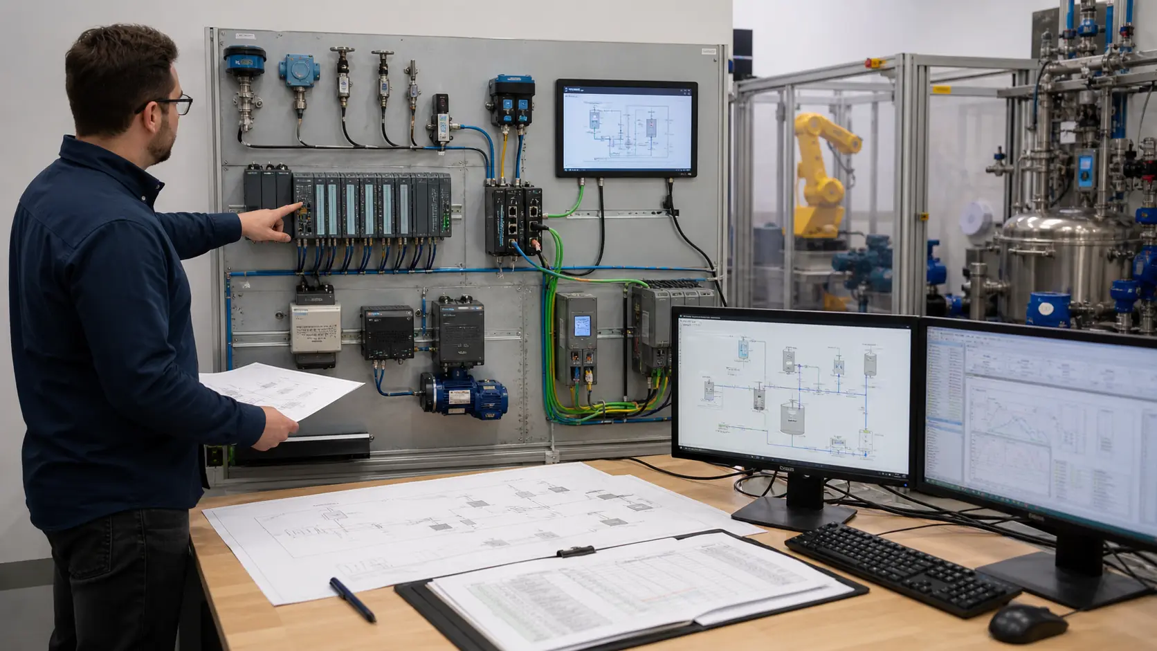
Training objective, shipped module, access tier, browser, runtime, instruction or device coverage, model fidelity, evidence, limits and update date.
Published capability through accessible workflow and runtime behavior to observable result, retained proof and explicit unsupported boundary.
One representative PLC, motor, process, HMI, network and robot task opened and tested against the matrix.
Marketing label without route, unsupported instruction, hidden entitlement, browser mismatch, stale documentation, missing data and target assumption.
A discovery, access, content, runtime, model, evidence, documentation, entitlement or expectation mismatch.
The shortlist validated by running representative work and recording current platform and target-equipment gaps.
Use the current capability matrix to verify specific PLC, wiring, motor, process, HMI, network and robot surfaces and the evidence each produces.
No. It teaches and tests bounded control behavior; exact firmware, native projects, I/O, networks, safety and commissioning remain target-specific.