1. Define the symptom
Record the machine mode, operator request, protection state and observed response. “Motor does not start” is useful only after confirming what command was actually given.
Industrial electrical training · motor control · fault diagnosis
Learn control drawings, contactors, overloads and the diagnostic sequence on hidden motor-control faults. The circuit reacts, the virtual multimeter records each test choice, and the simulator scores the diagnosis.
No install. No credit card. Get a visible result before creating an account.
Current scope: industrial motor-control diagnosis across DOL, reversing and star-delta circuits. It is training evidence, not a safety credential or practical competency authorization.
Industrial electrical curriculum
A practical path starts with control and power diagrams, then contactors, overloads, seal-in circuits, reversing and star-delta interlocks. Learners diagnose unseen faults only after they can explain the healthy circuit.
Free implementation toolkit
Map the browser work to supervised physical checks and measure training transfer.
Download PDFIndustrial electrical fault-finding in context
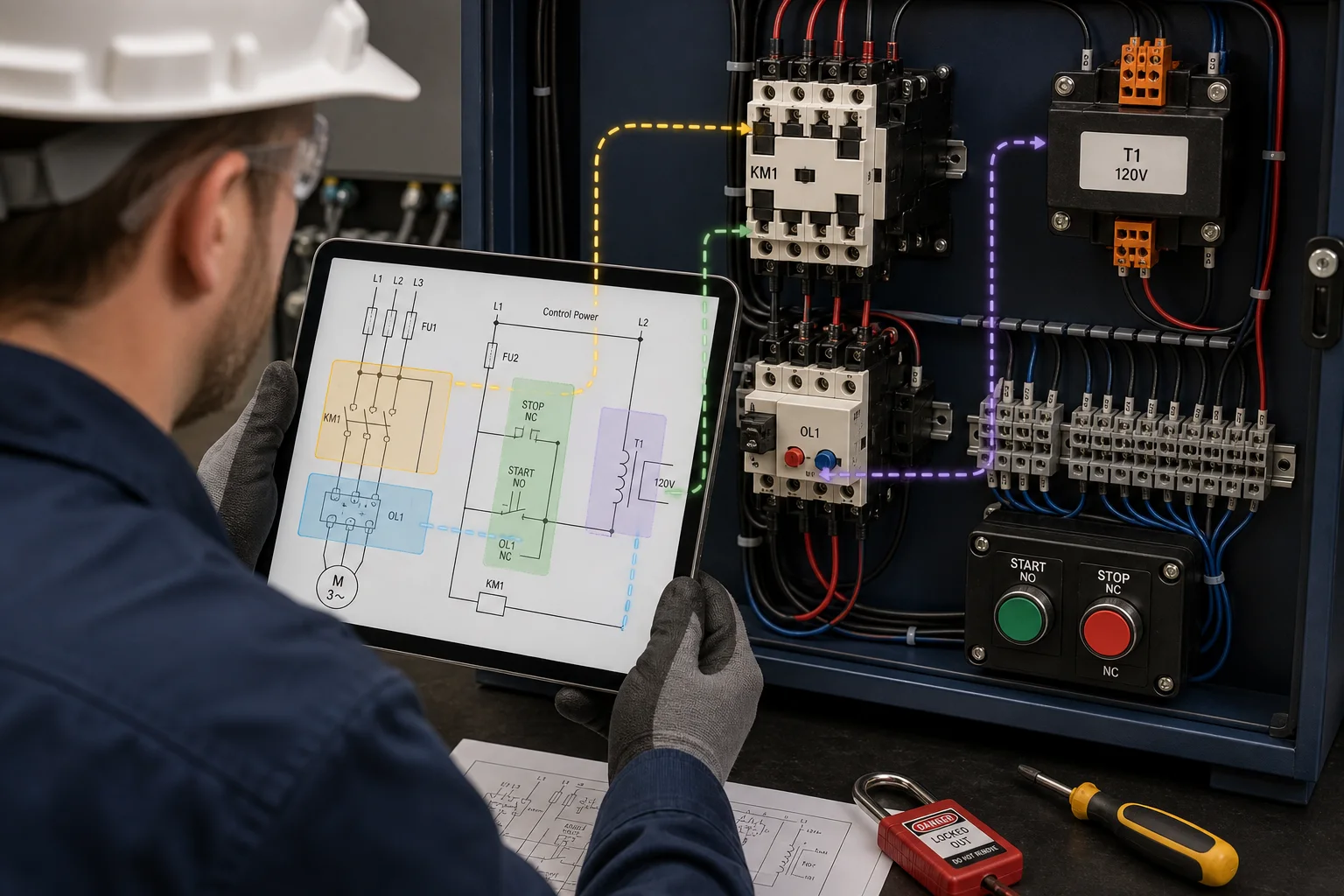
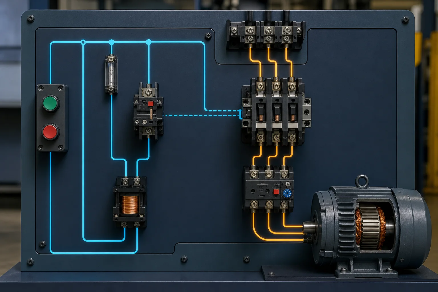
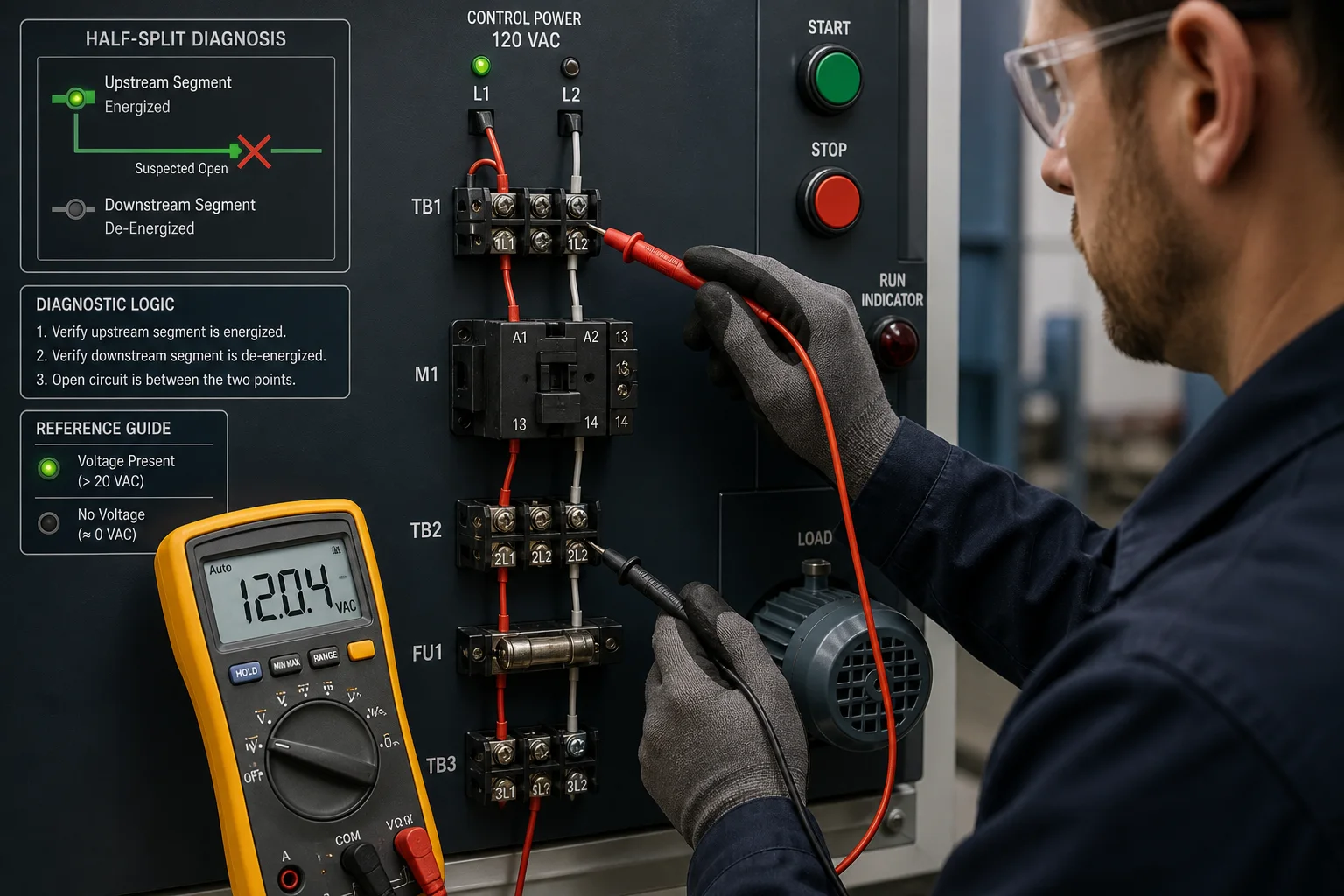
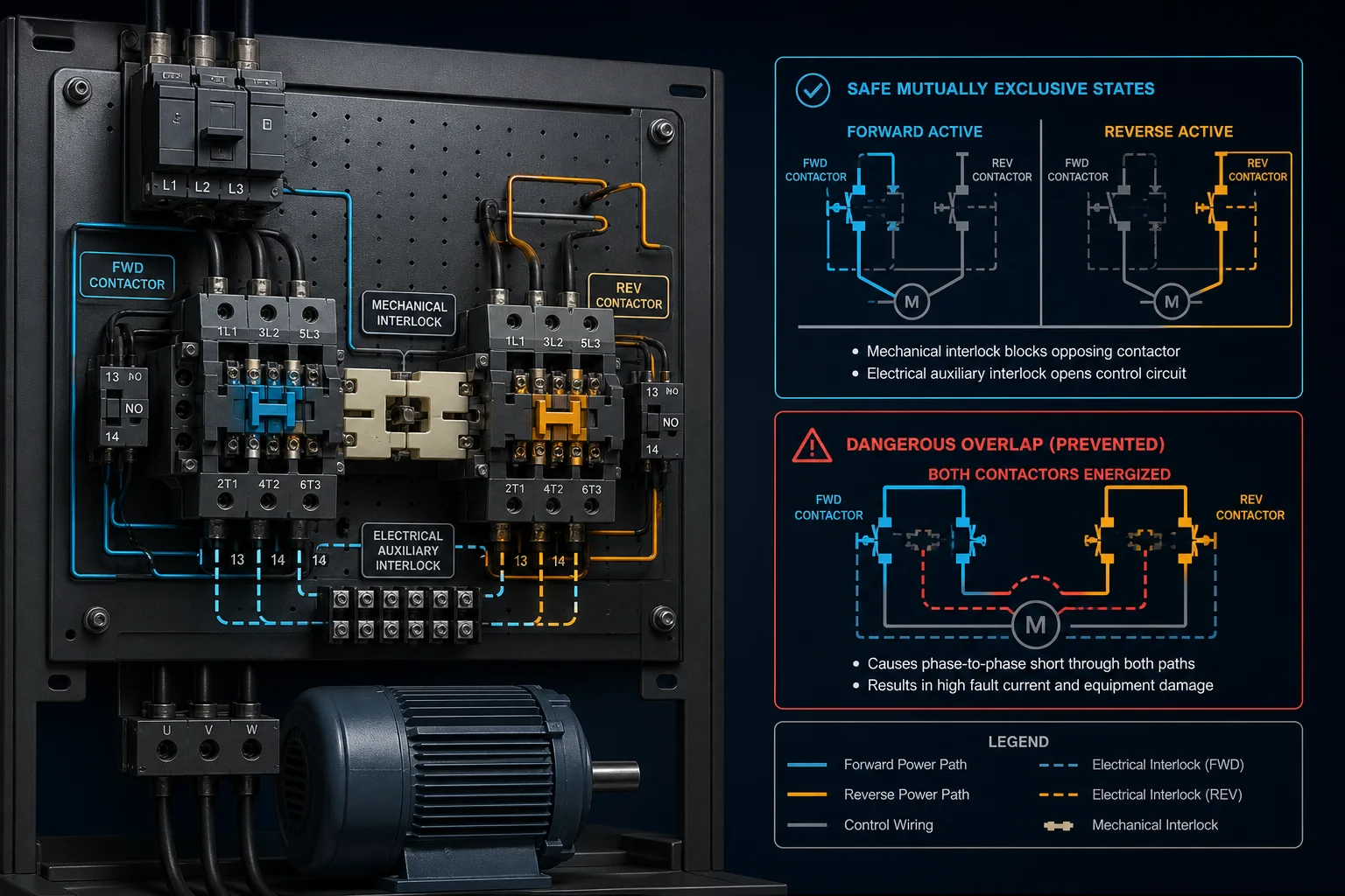
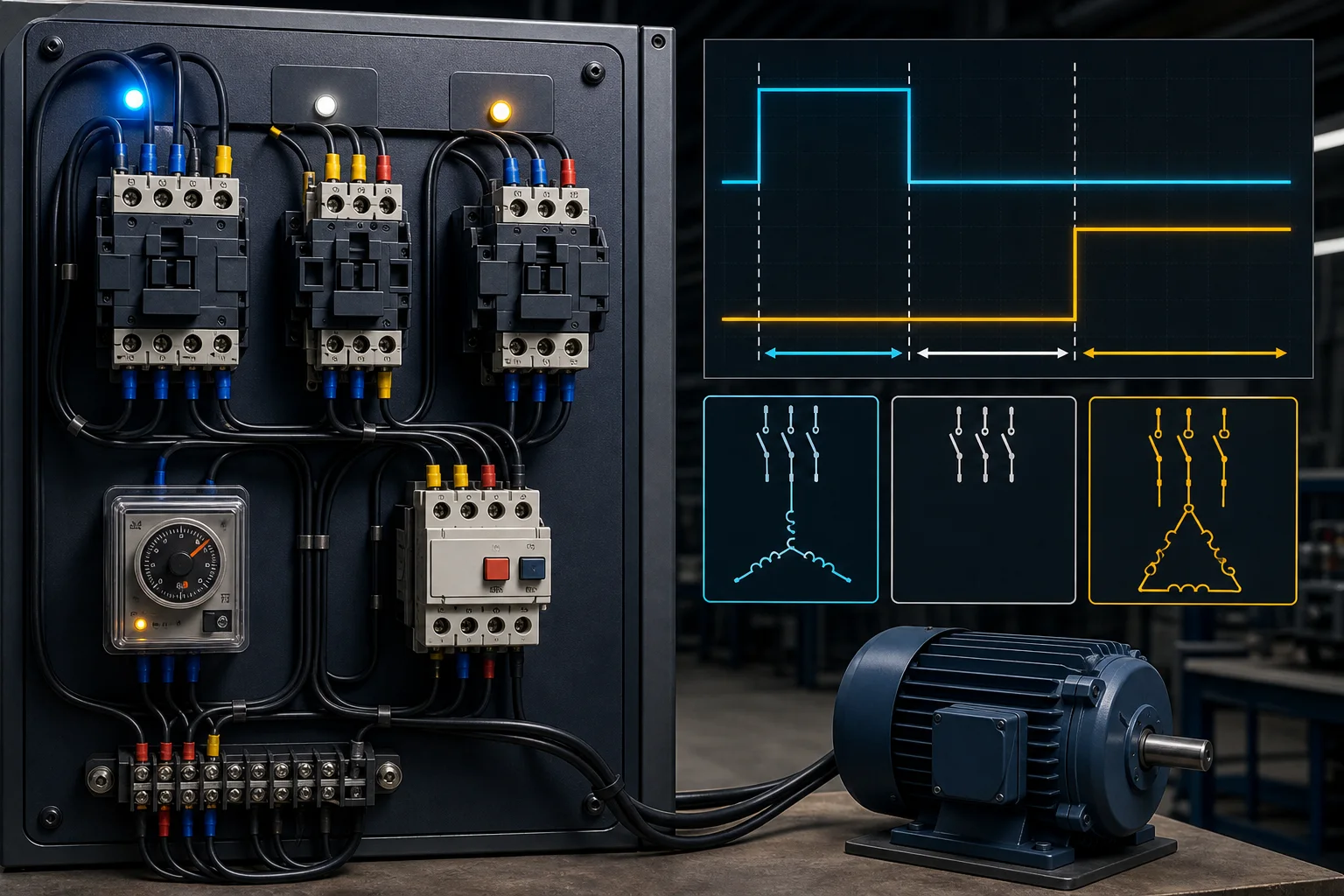
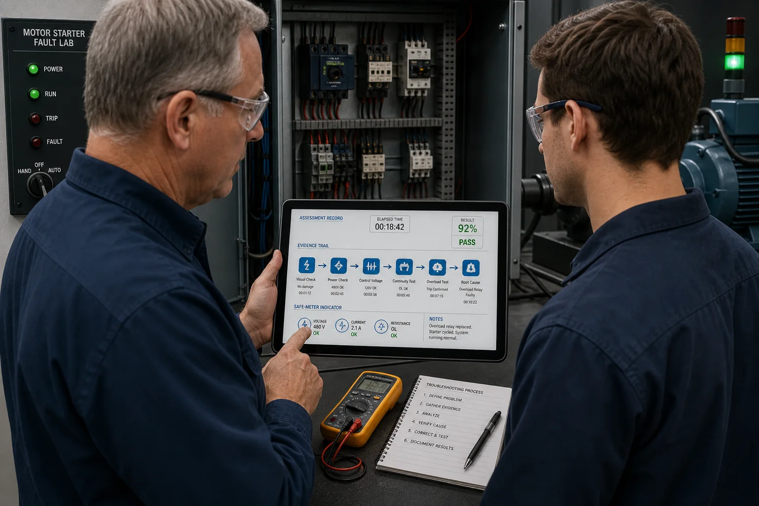
Each view connects a real motor-control concept to the evidence a technician should collect. The visual sequence moves from drawing-to-panel recognition through control and power paths, discriminating measurements, interlocks, timed transitions and assessment review.
Answer-first troubleshooting guide
Make the equipment safe under the applicable site procedure, define the exact symptom, trace the drawing from source to load, and take the one measurement that best separates the remaining causes.
A good diagnosis is an evidence chain. It explains what should happen, what actually happened, where those states first diverged, and why the proposed fault accounts for every relevant reading. Replacing the first suspicious part can restore a machine by chance; it does not demonstrate troubleshooting competence.
Record the machine mode, operator request, protection state and observed response. “Motor does not start” is useful only after confirming what command was actually given.
Use the employer procedure and the requirements that apply to the task. A simulation can teach circuit reasoning, but it cannot authorize live work or verify isolation on real equipment.
Identify the control supply, fuse, stop chain, overload contact, command devices, contactor coil and return. Trace three-phase supply, main poles, overload and motor separately.
Choose a circuit boundary near the middle of the unresolved path. The result should remove multiple possible causes rather than merely confirm one component looks healthy.
Use the appropriate instrument, category, leads and method under the site procedure. In the simulated workbench, voltage evidence is separated from isolated continuity practice.
After correcting the cause, prove more than one successful start. Test Stop, overload, interlocks and recovery so the repair has not introduced a dangerous alternate state.
It can show whether a learner reads the circuit, distinguishes control from power, chooses discriminating tests, avoids blocked unsafe meter combinations in the model, finds the root cause and explains the verification sequence. Saved attempts make those decisions reviewable.
Hazard recognition on the actual equipment, energy isolation, absence-of-voltage verification, instrument inspection and use, PPE, approach boundaries and employer authorization remain physical, task-specific responsibilities. Browser completion is not qualified-person status.
Why simulation fits this skill
A slide can describe a contactor. A scored simulation can reveal whether a learner distinguishes command voltage from power-path voltage, chooses an appropriate meter mode, finds the first unexpected circuit state and commits to the diagnosis.
Every learner can receive the same fault family without waiting for a physical rig to be rewired.
Wrong diagnoses and unsafe meter choices remain visible in the record.
Member passes, averages, best scores and last activity sit beside existing team progress.
Admins can export learner progress as CSV for internal review or LMS-adjacent workflows.
Visual field guide
The visuals cover pilot design, data flow, assessment scope, record fields, meter behavior, buyer contexts, implementation and the coaching loop.
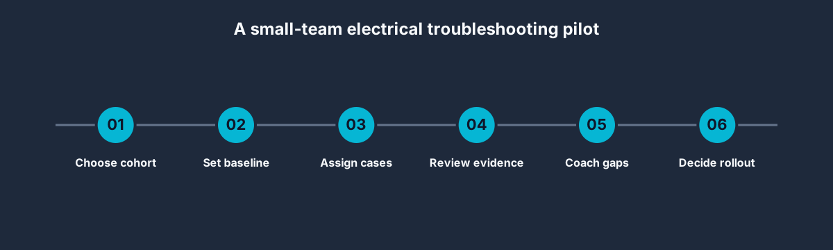
Pilot design
A focused pilot tests instructional value, completion behavior and reporting before a wider seat commitment.

Evidence flow
The learner interaction and the reporting layer share one source of truth instead of relying on a self-reported completion checkbox.
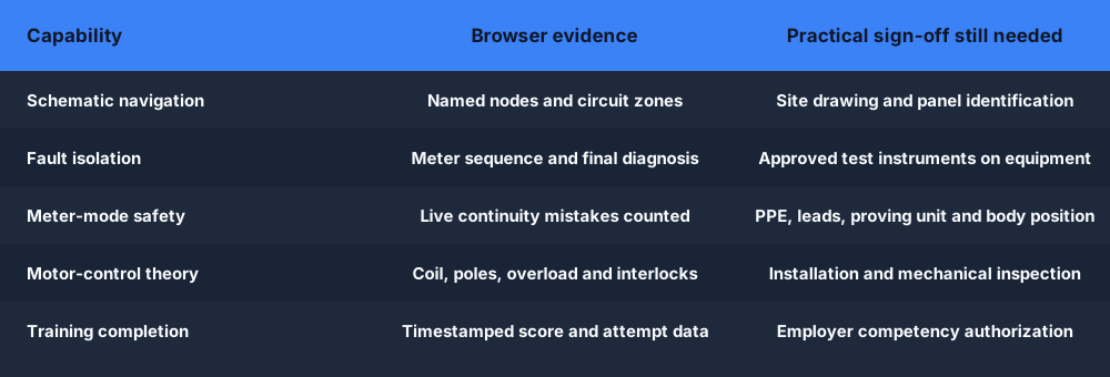
Scope
Circuit reasoning, diagnosis and meter-mode choices are visible. Practical PPE, instrument handling and real-equipment authorization are not.
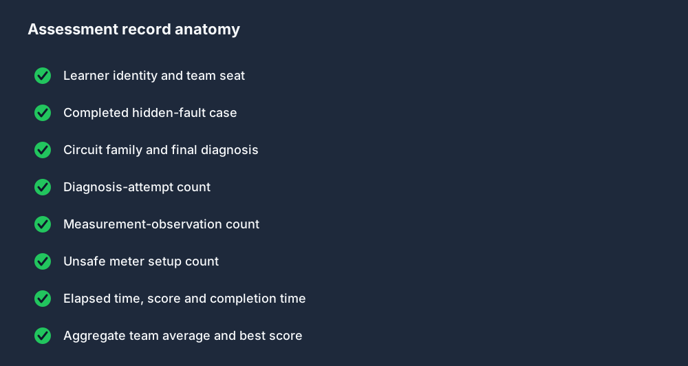
Record anatomy
Attempts and safety mistakes show where coaching is needed even when two learners both reach the correct answer.
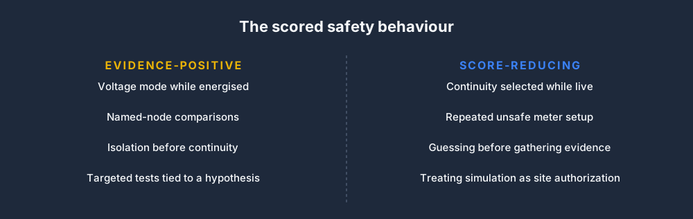
Safety behavior
The model blocks live continuity and records the choice, reinforcing the distinction between energised voltage diagnosis and isolated resistance tests.
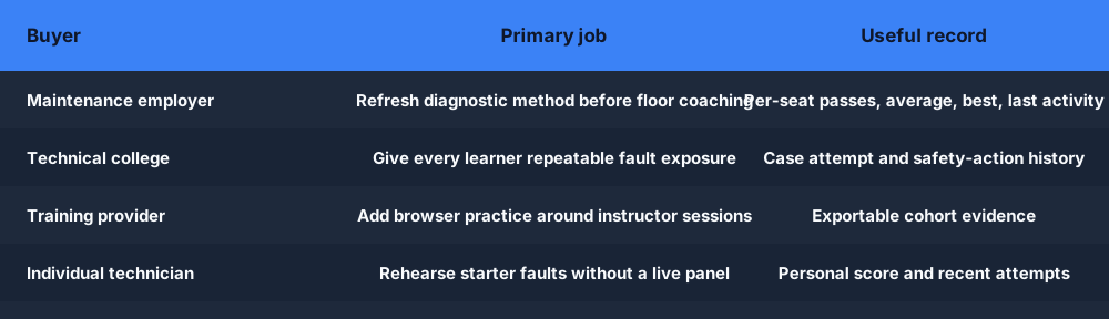
Use cases
Teams use the same simulation core while their assignment, review and purchasing paths remain separate from individual learning.
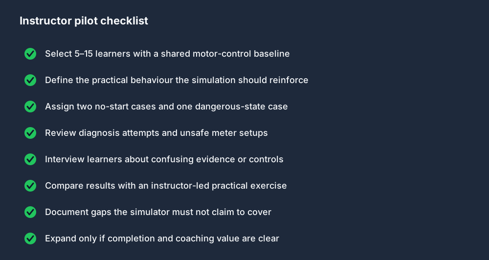
Implementation
Define the target behavior, select cases, review evidence, compare with a practical exercise and document the simulation boundary.
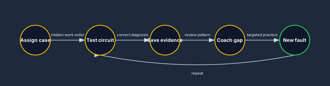
Learning loop
A saved record becomes the input to coaching and targeted repetition, not the end of the learning process.
What ships now
Learners use the same login and motor-control engine already in PLC Simulator Pro. The dedicated assessment route removes the visible fault controls, records the attempt and feeds the existing team reporting layer.
DOL supply, stop, coil, contact, overload and phase cases plus reversing and star-delta interlocks.
Named control and power nodes, voltage, isolated continuity and an explicit live-mode safety block.
Correct fault, diagnosis count and unsafe test choices determine a transparent 70–100 score.
Per-member passes, average, best, last activity and a CSV export alongside existing progress.
Pilot before rollout
Choose two no-start cases and one dangerous-state case. Review completion, diagnosis attempts and unsafe setups, then compare the browser record with an instructor-led practical exercise. That produces the evidence for a real rollout decision.
The record shows what happened inside a simulation. It does not certify a learner for energized work, lockout/tagout, PPE selection or any standard-specific requirement. Those remain the responsibility of the employer or institution. For plain-language background, see lockout/tagout explained and arc flash basics.
Electrical fault-finding field guide
Direct answer
Electrical troubleshooting training should teach a repeatable circuit method: establish the safe working state, understand the schematic, predict voltage or continuity at named points, divide the circuit at useful boundaries, confirm one cause and then prove every affected function after repair.
This guide is written for industrial electricians, maintenance technicians and automation learners who need structured practice across 24 VDC controls, contactors, overloads, PLC I/O and three-phase motor circuits. The intended result is specific: the learner can use a schematic and correctly configured meter to distinguish an open supply, failed protective contact, missing command, open coil, welded pole, missing phase or load problem without trial-and-error replacement.
Read source, protection, normally closed stop chain, commands, coil and return as a complete circuit before placing a probe.
State whether a reading is line-to-line, line-to-neutral, positive-to-common or across a component; a voltage number without reference is ambiguous.
Measuring across a closed contact and measuring each side to common answer different questions and must be interpreted deliberately.
A healthy coil circuit does not prove all contactor poles, overload elements, phases or the motor load are healthy.
Voltage, resistance and continuity modes use different internal behavior. Verify leads, range and energy state before connecting the instrument.
After correction, prove start, stop, overload, interlock, direction and feedback behavior rather than accepting one successful start.
Record which device failed, which commands were present and which related functions still worked.
Evidence: A precise statement bounds the circuit and likely energy path.
Avoid: Beginning with the component that failed last time.
Identify sources, protection, switches, coils, contacts, terminals and cross-references.
Evidence: Expected open and closed states are written for the present machine mode.
Avoid: Tracing wire color alone without circuit function.
Follow the site procedure for isolation, lockout, dissipation and verification before exposed or continuity work.
Evidence: The approved zero-energy condition is independently verified.
Avoid: Treating a PLC output-off indication as isolation.
Select a midpoint that separates possible upstream and downstream failures.
Evidence: One safe reading eliminates approximately half the remaining path.
Avoid: Measuring every terminal without a hypothesis.
Measure the suspected boundary using the mode and reference appropriate to the energy state.
Evidence: Expected healthy and failed readings are stated before the test.
Avoid: Calling a component bad from one unexplained value.
Repair, inspect, restore barriers and test normal plus protective behavior.
Evidence: All affected functions pass and no temporary jumper remains.
Avoid: Testing only the original run command.
| Observed symptom | Inspect | Interpretation | Next proving action |
|---|---|---|---|
| No control voltage | Transformer or supply, upstream protection, control fuse and common return | If the reference supply is absent, downstream contact readings cannot be interpreted normally. | Restore the source problem before tracing logic devices. |
| Voltage stops at one contact | State and rating of the contact plus voltage on each side to the reference | An open contact may be correctly responding to a stop, overload or permissive—not necessarily defective. | Prove why the contact is open. |
| Full voltage across coil, no motion | Coil rating, continuity under isolation, mechanical binding and contactor condition | The command reached the load, shifting suspicion from controls to the coil or mechanism. | Isolate and test the coil according to approved procedure. |
| Contactor closes, motor idle | Main poles, overload path, phase-to-phase supply, motor terminals and mechanical load | The low-power decision circuit succeeded but the power path did not deliver usable three-phase energy. | Trace each phase and protection element. |
| Fuse opens again | Load current, short path, coil rating, damaged insulation and recent wiring changes | Repeated fuse operation is evidence of an unresolved cause, not a request for a larger fuse. | Find the overcurrent path before replacement. |
| Interlock fails | Normally closed auxiliary contact, mechanical block, wiring ownership and opposite-coil state | Forward/reverse overlap is a dangerous control defect requiring isolation. | Prove both electrical and mechanical prevention. |
Product evidence / 05
The simulator provides recognizable control hardware, named probe nodes, live voltage, isolated continuity, hidden faults, safety-action tracking and scored diagnoses. The circuit and measured state change together, so readings have electrical meaning.
Clarify the symptom and establish the safe working condition. Do not place probes until you understand the energy state, circuit reference and purpose of the test.
It can be useful, but interpret it correctly. A closed healthy contact normally has little voltage across it; an open contact can show source voltage if the downstream return path exists.
The contactor may have an open or welded main pole, the overload may be open, a phase may be missing, the motor circuit may be disconnected or the mechanical load may be blocked.
Only on a circuit placed in the approved de-energized state and after stored energy is controlled. Confirm the meter and component instructions before testing.
Verify the reference supply, then move through the series path or divide it at a midpoint. Compare measured state with the schematic and present machine condition.
Retain the fault scenario, safety actions, meter mode, probe nodes, readings, diagnosis, correction and functional proving result.
Usually not. It identifies a detected condition. Trace the alarm input through controller state and physical evidence before assigning a component cause.
No. It supports circuit reasoning and safe habits, but real competence requires qualified supervision, physical instruments, employer procedures and equipment-specific training.
Watch the real browser product respond to the task on this page, then try the same practical workflow yourself. No slides, concept mockups, install, or credit card.
Try this in the browserTroubleshooting learning path
Establish the expected state, isolate the failed signal path, test one hypothesis and prove the repair under the original conditions.