Concealed diagnosis
The assessment view removes the visible fault picker and fault-revealing schematic marks.
Operate a real motor-control model, place virtual multimeter probes on named nodes, avoid unsafe test modes and submit the diagnosis. The fault changes the circuit—the answer is not written into the story.
Quick answer: the simulator covers control-supply, stop-chain, coil, contact, overload, phase and interlock faults across DOL, reversing and star-delta circuits. Pro adds concealed cases, scoring and saved records.
Experiential, not slide based
Each case starts the same tested motor-control engine with one server-selected fault. Inputs, coils, auxiliary contacts, poles, voltage nodes, current, rpm and protection states remain connected, so one fault creates consistent symptoms across the workbench.
The assessment view removes the visible fault picker and fault-revealing schematic marks.
Measure control points from 24 V through A1–A2 and three-phase points from L to T.
Contactor commands, phase condition, current, rpm, direction and dangerous overlap update over time.
Correct attempts save diagnosis count, observations, safety mistakes, time and score.
Visual field guide
Each figure answers a separate search question: the troubleshooting process, circuit zones, half-split method, meter modes, fault evidence, scoring, attempt state and saved record.
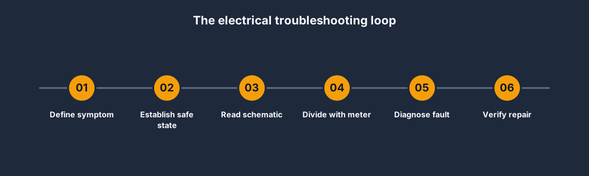
Method
The workbench rewards a circuit hypothesis and a discriminating measurement—not random component swapping.

Circuit map
A healthy coil command does not prove the three-phase path. Each zone has named evidence and a different fault family.
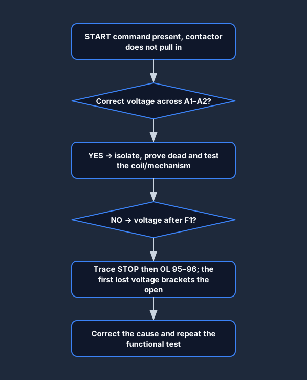
Meter strategy
Measure at a point that divides the remaining suspects. The next test follows from the result.
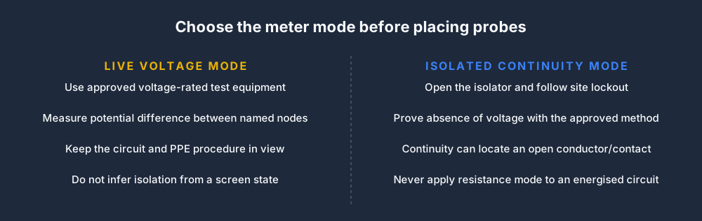
Meter safety
The simulator permits voltage evidence while energised and blocks resistance or continuity on the live model.
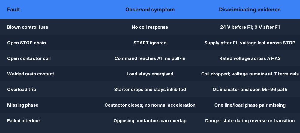
Fault library
Fuse, stop, coil, pole, overload, phase and interlock failures change the actual circuit model instead of revealing a scripted answer.
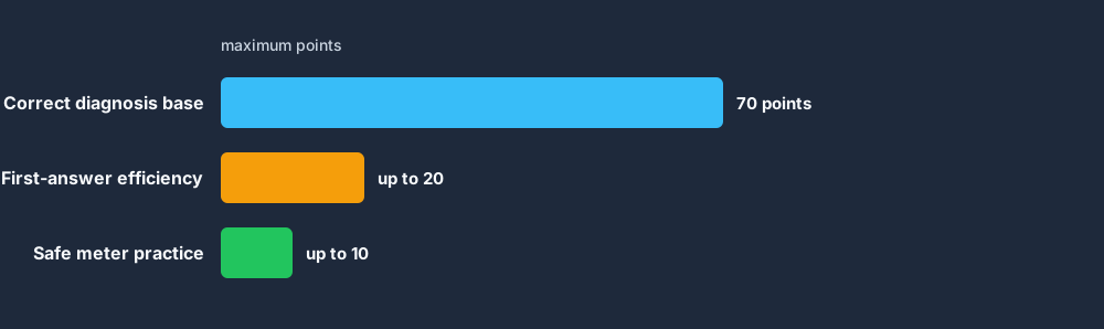
Scoring
The server owns the final answer and score. Wrong diagnoses remain part of the attempt instead of resetting the exercise.
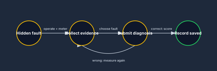
State machine
An incorrect submission returns the learner to evidence gathering. A completed attempt is idempotent and cannot be scored twice.
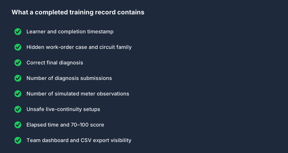
Training evidence
Individuals see recent attempts; team administrators receive member-level rollups and an exportable evidence trail.
Current case library
The library begins with starter circuits because they connect control logic, real components, three-phase power and a measurable load. It does not currently claim general residential wiring, PCB repair, arc-flash calculation or safety certification.
No contactor response; line power may still be present.
Best first evidence: Compare 24 V before and after F1.
START is ignored despite a healthy supply.
Best first evidence: Trace the first lost voltage through the fail-safe series path.
Command voltage reaches A1–A2 but the contactor does not pull in.
Best first evidence: Use live voltage evidence, then isolated continuity.
Load-side voltage remains after the coil command drops.
Best first evidence: Treat the mismatched coil and pole state as dangerous.
The starter stops and the 95–96 path remains open.
Best first evidence: Identify protection state before attempting a reset.
The contactor closes but the motor will not accelerate normally.
Best first evidence: Compare every line and load phase pair.
Opposing contactors can overlap during reversal or transition.
Best first evidence: Observe the dangerous state, isolate and diagnose the interlock.
Assessment records
A completed simulation saves more than a completion tick. It records whether the learner diagnosed efficiently, gathered meter evidence and avoided an unsafe meter setup. Team rollups expose passes, average and best score per member.
See team trainingThe hidden work order and motor-control family
Correct fault and number of submissions
Measurement observations and unsafe setups
Elapsed time, 70–100 score and timestamp
This browser lab develops circuit reasoning and test-selection habits. It does not prove practical competence, authorize electrical work, select PPE, perform a real absence-of-voltage test or replace employer and jurisdictional procedures.
Same login · separate assessment tier
The assessment is built into the existing PLC Simulator Pro app, while the employer path keeps its own reporting, messaging and team workflow.
Runnable simulator field guide
Direct answer
The learner can state expected readings, locate the first electrical disagreement, identify one cause and prove restoration without trial-and-error replacement.
Written for electrical and maintenance learners practicing schematic interpretation, safe-state decisions, voltage patterns and controlled fault isolation.
The circuit purpose, energy state, normal sequence, named nodes, approved measurement and expected readings.
Source through protection, contacts, coil or load and return with controller and physical feedback where applicable.
Normal control voltage, continuity in an isolated state and resulting device behavior.
Open conductors, failed contacts, blown protection, wrong reference, phase loss and intermittent feedback.
One hidden fault divided at the safest useful measurement boundary.
Cause removal, bypass removal, stop-path test, normal operation and documented handover.
Troubleshooting learning path
Establish the expected state, isolate the failed signal path, test one hypothesis and prove the repair under the original conditions.