Quick answer: Electrical troubleshooting is the process of turning a symptom into a testable circuit question, choosing the safe energy state, comparing measured values with the schematic, isolating the smallest faulty section, correcting the cause, and verifying the complete function. A good measurement should eliminate possibilities; random probing only creates readings.
The fastest troubleshooters are not the people who memorize the most failures. They are the people who keep the circuit, the symptom, the energy state and the evidence aligned. They can explain what a measurement is expected to show before the probes touch a test point—and what each possible result would mean.
This guide uses a conventional motor starter because its control and power paths expose the method clearly. The same logic applies to relays, solenoids, heaters, pumps, conveyors and many PLC-controlled outputs.
The seven-step electrical troubleshooting method
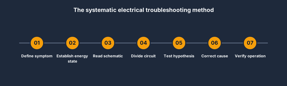
- Define the symptom precisely. “Motor does not run” is incomplete. Does the contactor pull in? Did the overload trip? Is the fault constant or intermittent? What changed immediately before it appeared?
- Establish the energy state. Decide whether the next question can be answered de-energised. Follow the employer’s isolation, lockout, absence-of-voltage, PPE and live-work procedures. A browser simulation never authorizes work on real equipment.
- Read the current schematic. Mark the expected current path from source to load and return. Identify protective devices, normally closed stop contacts, permissives, interlocks, commands, coils and main power poles.
- Divide the circuit. Choose a measurement near the middle of the suspected path. The result should eliminate roughly half of the remaining circuit.
- Test one hypothesis. State the expected values for both a healthy and faulty condition. Use voltage on an energised diagnostic path only under an approved procedure; use continuity or resistance only after the required isolation and proof.
- Correct the cause, not only the symptom. A reset can restore operation without explaining a trip. A new fuse can clear a symptom without finding the short that opened it.
- Verify the entire function. Repeat the original condition, test stops and protections, observe loaded behavior and record what proved the repair.
Step 1: turn the complaint into an observable symptom
Ask questions that separate control, power and load faults:
- Did the machine stop while running, fail on startup, or behave incorrectly after a change?
- Does a contactor, relay or valve coil energise?
- Is an overload, fuse, breaker or drive showing a trip state?
- Does the PLC output indicator agree with the physical output?
- Is the failure tied to temperature, vibration, time, product, speed or direction?
- Can the symptom be reproduced without creating additional risk?
Record the original state before resetting anything. Trip indicators, relay states, event timestamps and operator context often disappear when power is cycled.
Step 2: choose the safe energy state before the meter mode
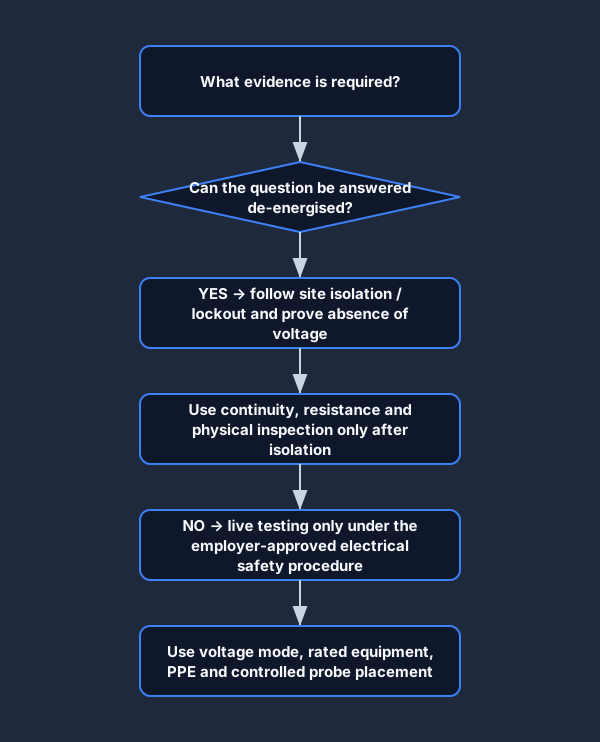
The test method follows the question—not convenience. Visual inspection, terminal security, coil resistance and conductor continuity can often be checked de-energised. Voltage drop and command-state questions may require energised evidence, but only within the applicable employer procedure and by people authorized and equipped for that work.
OSHA’s electrical work-practice rule in the United States begins from de-energising exposed live parts before work unless a stated exception applies. Your jurisdiction and site may impose additional requirements; use the current rules and the employer’s energy-control procedure, not this article, as the authority. See OSHA 29 CFR 1910.333.
Two meter rules prevent common mistakes:
- Resistance and continuity modes are for the isolated state required by the procedure. The meter applies its own test source; it is not a substitute voltage detector.
- A screen showing “OFF” is not proof of absence of voltage. Use the approved isolation and verification method on the real circuit.
Step 3: read the circuit as a chain of permissions

A typical starter control path is:
control supply → fuse → STOP NC → overload 95–96 NC → permissive/interlock → START or seal-in path → coil A1 → coil A2/return
Every series element must permit current before the coil can energise. That gives each test point meaning. Voltage before a device but not after it indicates that the path opens at that device or its immediate connection. Rated voltage across A1–A2 with no mechanical pull-in shifts the hypothesis from upstream wiring to the coil or contactor mechanism.
The power circuit is separate:
L1/L2/L3 → disconnect/protection → contactor main poles → overload power elements → T1/T2/T3 → motor
A healthy control circuit cannot guarantee a healthy power circuit. A contactor can pull in while one main pole, phase conductor or motor lead remains open.
Step 4: use half-splitting instead of walking every terminal
Half-splitting means measuring near the middle of the remaining suspect path. If the expected value is present, the source side is provisionally healthy and the search moves toward the load. If absent, the search moves toward the source.
For a no-start circuit with no voltage across A1–A2:
- Measure at the output of the control fuse.
- If healthy, measure after the stop/overload chain.
- If healthy, inspect the command, permissive and coil return segment.
- If unhealthy, move upstream and bracket the first point where voltage disappears.
The aim is not the largest number of readings. It is the smallest set of readings that uniquely separates the likely causes.
Step 5: interpret patterns, not isolated numbers
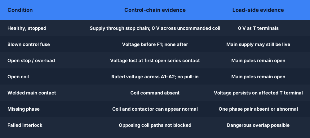
A single value becomes useful only when compared with the expected state:
- Voltage before F1, none after: the fuse or its connection is open. Find why before replacement.
- Control voltage reaches the stop chain but not the coil: locate the first series device where the potential changes unexpectedly.
- Rated voltage across A1–A2, no pull-in: isolate and investigate coil continuity, coil rating, terminals and mechanism.
- No coil command but load-side voltage remains: treat a welded main contact as a dangerous power-circuit failure and isolate.
- Contactor closes but the motor does not accelerate: compare all phase pairs on the line and load sides, then investigate cable, motor and mechanical load under the approved procedure.
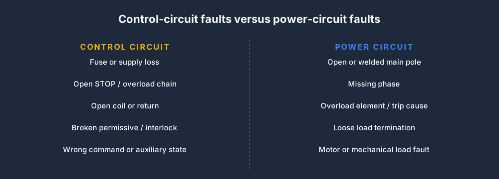
Control faults usually explain why the contactor was not commanded or could not energise. Power faults explain why a commanded contactor did not deliver healthy energy to the load—or why energy remained when it should not.
A no-start decision tree
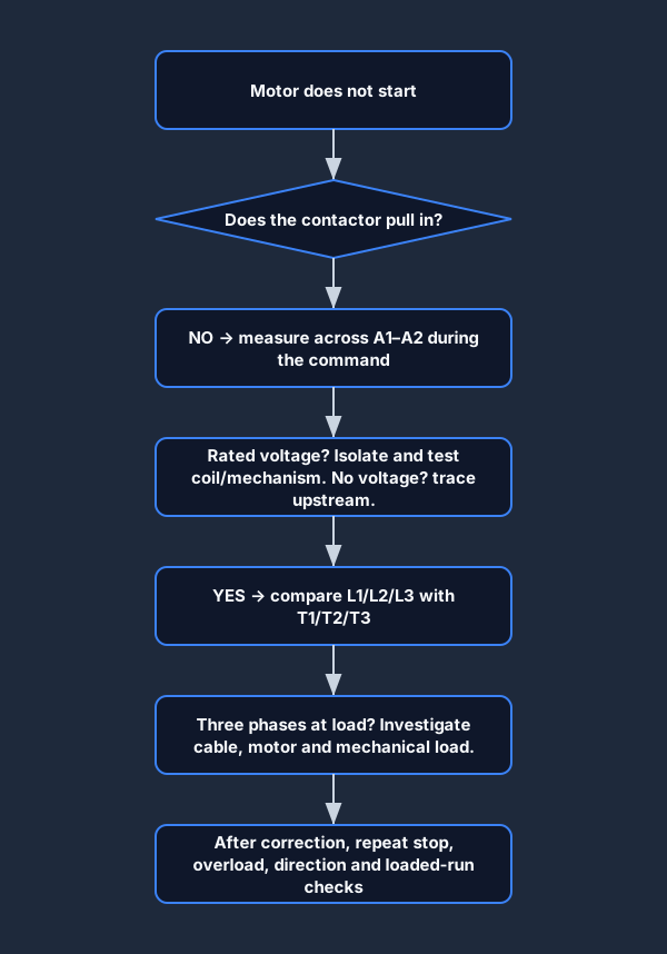
Start with the visible state of the contactor:
- Contactor does not pull in: measure across the coil during a valid command. Rated coil voltage points to the coil/mechanism after isolation. No voltage points upstream into the control chain.
- Contactor pulls in: the command path has done its job. Compare the three-phase line side with the load side, then the motor terminals and mechanical load.
- Contactor drops unexpectedly: inspect STOP, overload and permissive states before resetting. Determine whether protection operated correctly or a control path opened unintentionally.
- Load remains energised after the coil drops: isolate immediately and investigate welded or mechanically failed power contacts.
For the narrower starter-specific version—with overload and contactor details—use the motor starter troubleshooting guide. To practice the live state changes in a safe model, open the electrical troubleshooting simulator.
Common troubleshooting errors
Replacing the component named by the alarm
An overload alarm reports a state, not necessarily a failed overload relay. The relay may be correctly responding to excess current, phase loss, a jam, repeated starts or a setting problem.
Measuring continuity on a live circuit
This is both unsafe and conceptually wrong. Select the energy state first, then the appropriate meter function. The simulator deliberately counts live-continuity selections as unsafe setups so the meter choice becomes part of the training evidence.
Trusting an indicator instead of the electrical point
A PLC tag, output LED, HMI graphic or contactor sound is useful context, but it does not prove the voltage at A1, the state of the main poles or the voltage at the motor terminals.
Stopping when the machine moves
Removing the symptom is not verification. A bypass, repeated reset or disturbed loose terminal can restore motion temporarily while leaving the cause unresolved.
Step 6 and 7: correct the cause and verify the repair
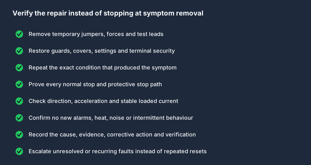
Verification should include more than the repaired branch. Restore the circuit to its intended state, remove temporary test measures, repeat the original operating condition, prove normal and protective stops, check direction and loaded behavior, and record the evidence.
If the fault is intermittent, define an observation window or logging method. “It ran once” is weak evidence for a heat-, vibration- or timing-dependent failure.
Practice the method in a browser
The browser-based electrical troubleshooting simulator hides one of seven motor-control faults inside a live circuit model. You can operate the starter, place virtual meter probes on named nodes and submit a diagnosis. Pro users receive a score based on the correct diagnosis, number of diagnosis attempts and safe meter-mode choices. Team admins can review and export completed evidence records.
The simulation is intentionally scoped: it builds circuit reasoning and safe test-selection habits, but does not certify competence, replace supervised practical assessment or authorize real electrical work.
Frequently asked questions
What are the basic steps in electrical troubleshooting?
Define the symptom, establish the safe energy state, read the schematic, divide the suspected circuit, test one hypothesis, correct the root cause, and verify the complete function.
How do you troubleshoot a control circuit with a multimeter?
Mark the expected source-to-coil path on the schematic. Under the approved procedure, compare voltage at selected points and bracket the first unexpected change. Use resistance or continuity only in the required isolated and verified state.
What is the half-split method?
It is a search strategy: test near the middle of the remaining suspect circuit so one result eliminates the source-side half and the other eliminates the load-side half.
Can an electrical troubleshooting simulator replace practical training?
No. It can provide repeatable circuit, meter-selection and diagnosis practice without real energy. Practical skills, PPE, test-equipment use, isolation and employer authorization still require suitable real-world training and assessment.
Why should an overload trip be diagnosed before reset?
Because the overload may have operated correctly in response to a load, current, phase or starting problem. Resetting clears the state but does not remove the cause.