If you have tried to make a motor run when you press a button and stay running when you release it, you have already hit the problem that the seal-in rung solves.
A seal-in rung (also called a latch rung or maintaining circuit) is a branch in ladder logic that places a normally-open copy of the output coil in parallel with the start contact. Once the output energises, it keeps itself energised through its own contact — so releasing the momentary start button does not de-energise the output.
Why You Cannot Just Use a Single Contact
A momentary pushbutton is closed only while you press it. If your rung is simply:
|--[StartButton]--[/StopButton]--( MotorRun )--|
The motor energises when StartButton is pressed. The moment you release it, StartButton opens, the rung goes false, and MotorRun de-energises. The motor stops. That is not a useful motor starter.
The solution is to give MotorRun a second path to stay true:
The Classic Seal-In Circuit
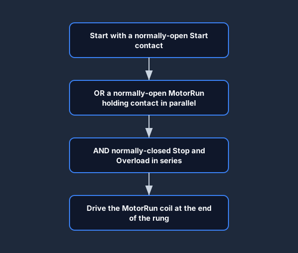
|--[StartButton]--+--[/StopButton]--[/Overload]--( MotorRun )--|
                  |
                  +--[MotorRun]---+
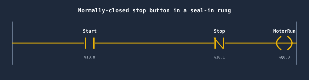
Because the generated rung diagram is drawn in series, the holding contact, Stop and Overload are shown in line below — but remember the MotorRun holding contact is wired as the OR-branch in parallel with the Start contact, exactly as the text diagram above shows.
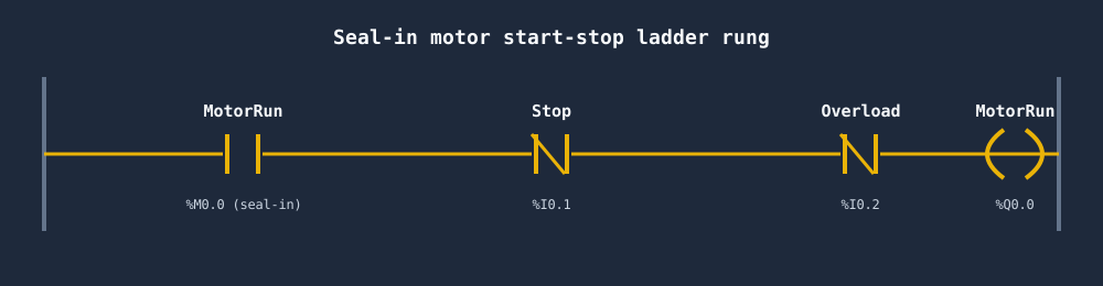
In text logic:
(* Seal-in motor starter *)
IF (StartButton OR MotorRun) AND NOT StopButton AND NOT Overload THEN
    MotorRun := TRUE;
ELSE
    MotorRun := FALSE;
END_IF;
Execution trace:
- Operator presses
StartButton. The OR condition becomes true.MotorRunenergises. - Operator releases
StartButton. NowMotorRunis already true, soMotorRun OR StartButtonis still true. The rung remains true. The motor keeps running. - Operator presses
StopButton.NOT StopButtonbecomes false. The rung goes false.MotorRunde-energises. The motor stops. - Next scan:
MotorRunis false,StartButtonis false — rung stays false. The seal-in is broken.
Plotted against time, the latch is obvious: a momentary Start pulse drives MotorRun high, it stays high through the seal-in after Start releases, and a Stop press drops it.
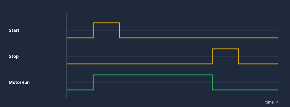
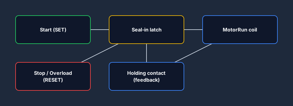
Conceptually this is a set/reset latch: Start sets the output, the seal-in branch holds it, and Stop or Overload resets it.
Safety Contacts: Always in Series, Never in Parallel
Notice that StopButton and Overload are placed in series on the rung, not in parallel. This is deliberate and safety-critical.
- Series contacts are AND logic. Any one of them can break the circuit and stop the motor.
- Parallel contacts are OR logic. Every one of them must be false simultaneously to de-energise the coil.
Always put your protective devices — stop buttons, overloads, E-stops, safety relays — in series on the rung. Never put them in the seal-in branch.
E-Stop Integration
A proper motor starter includes an Emergency Stop circuit. Typically the hardware E-stop is wired as a hardwired safety relay that cuts power to the output regardless of what the PLC program does. But at the software level you should also honour the E-stop:
(* Motor starter with E-stop, stop, and overload in series *)
IF (StartButton OR MotorRun)
   AND NOT StopButton
   AND NOT Overload
   AND NOT EStopFault THEN
    MotorRun := TRUE;
ELSE
    MotorRun := FALSE;
END_IF;
For a worked implementation of E-stop with monitored reset, see the E-Stop Reset scenario in the simulator.
Latch / Unlatch Coils: An Alternative Approach
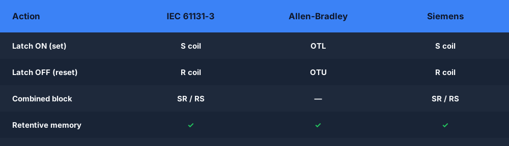
IEC 61131-3 also provides dedicated latch coils — S (Set) and R (Reset) — that behave like SR flip-flops:
(* Using Set/Reset coils *)
IF StartButton AND NOT Overload THEN
    MotorRun := TRUE;   (* Set coil — latches ON *)
END_IF;

IF StopButton OR Overload THEN
    MotorRun := FALSE;  (* Reset coil — latches OFF *)
END_IF;
Allen-Bradley equivalents are OTL (Output Latch) and OTU (Output Unlatch). Siemens TIA Portal uses S and R coils in ladder.
Seal-In vs Latch/Unlatch: Which to Use?
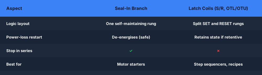
| Seal-In Branch | Latch/Unlatch Coils | |
|---|---|---|
| Code visibility | All logic on one rung | Split across two rungs |
| Power loss behavior | Coil de-energises | Coil retains state (if retentive) |
| Preferred for | Simple motor starters | Step sequencers, recipe selection |
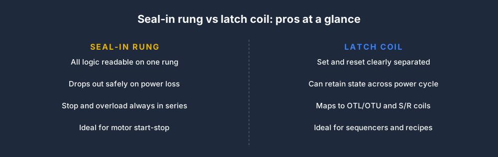
Latch coils are retentive — they remember their state across a power cycle if the memory is configured as retentive. This is useful for batch recipes and sequence steps but dangerous for safety outputs. Use seal-in rungs for motor starters that should always restart safely after a power outage.
Common Mistakes with Seal-In Rungs
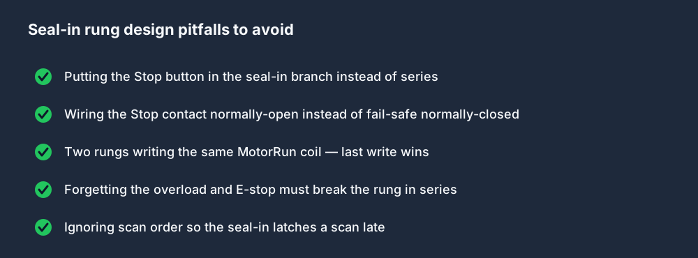
Mistake 1: The seal-in branch is in the wrong place
(* WRONG — stop button is in the seal-in branch, not series *)
|--[StartButton]--[/StopButton]--( MotorRun )--|
                       |
                       +--[MotorRun]--+
In this layout, pressing StopButton breaks the direct path but the seal-in path — through MotorRun alone — bypasses the stop button. The motor will not stop. This is a wiring equivalent of bypassing a safety circuit.
Mistake 2: Multiple coils writing the same bit
If you have two rungs that both write MotorRun, the last one wins. Only the final rung execution result matters at output scan time. Structure your logic so only one rung controls each coil.
Mistake 3: Forgetting normally-closed contacts
StopButton in the rung should be a normally-closed (NC) contact ([/StopButton]) if the physical pushbutton is a normally-open (NO) switch. A stop button wired as NC/NC — hardware NC and software NC — means you get a fault if the wire breaks (the broken wire opens the circuit, which the controller sees as the stop button pressed). This is called fail-safe wiring and is covered in IEC 60204-1.
Building Your First Seal-In Rung
The Motor Start/Stop scenario in the simulator walks you through building this from scratch. You will write the seal-in rung, run it against the simulation, and the auto-grader will verify that:
- The motor starts on a rising edge of the start button.
- The motor stays running after the start button releases.
- The motor stops immediately on the stop button.
- The motor stops on the overload signal.
For a broader understanding of ladder logic structure, read How to Read Ladder Logic (Step by Step) or dive into the Latching and Sealing-In lesson.
Practice this yourself in the simulator — 3 scenarios free. No install. No credit card. Write real ladder logic against a live machine model in your browser.