PLC Simulator
Industrial automation training online

Train the complete controls stack—not isolated symbols

Move from field devices and motor circuits to PLC sequences, analog control, HMI operation, robotics and complete 3D factory floors. Every lab makes the learner prove normal operation, abnormal response and deliberate recovery.

Live training model

3D Conveyor Sort

01

PLC logic executes against a dynamic machine or process model

02

Typed I/O joins sensors, drives, actuators, HMI and safety states

03

Fault injection turns troubleshooting into observable practice

04

Objective checkpoints retain evidence beyond video completion

Physics running · PLC scan active · grader armed

A complete controls stack

Learn how industrial automation behaves as a system

Technicians rarely troubleshoot one isolated device. The useful skill is following a command and its feedback through sensors, controller logic, safety, motor control, pneumatics and the operator interface.
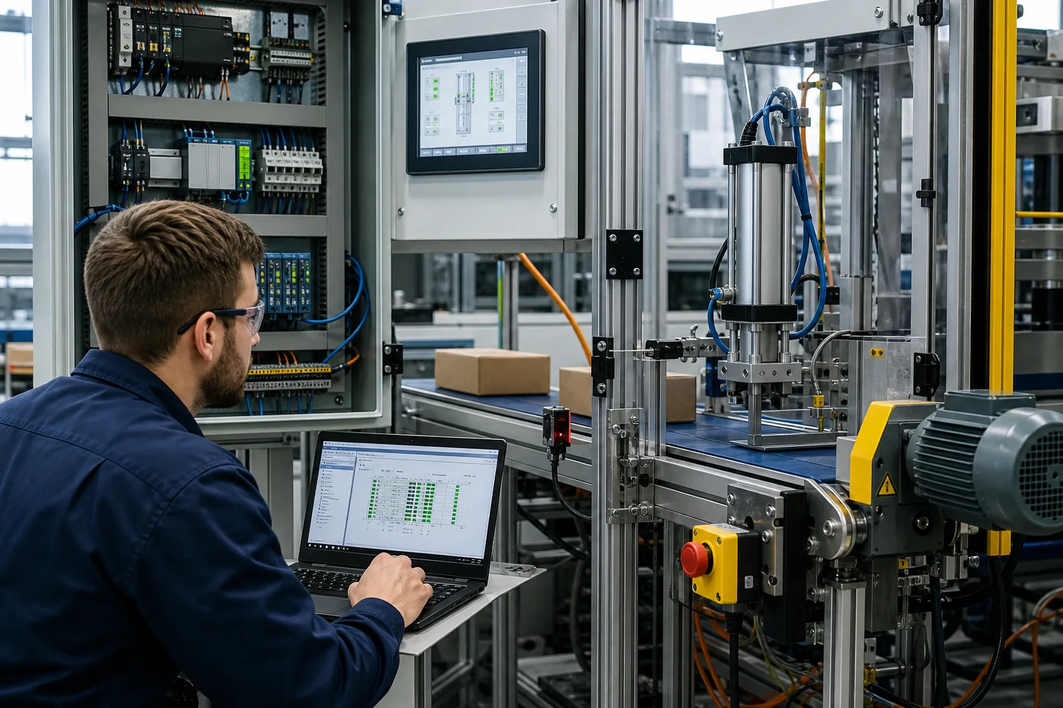
Automation technician commissioning a conveyor and pneumatic packaging training cell with PLC and HMI
01Commission a real sequence by checking field I/O, safety state, PLC logic and visible machine motion together.
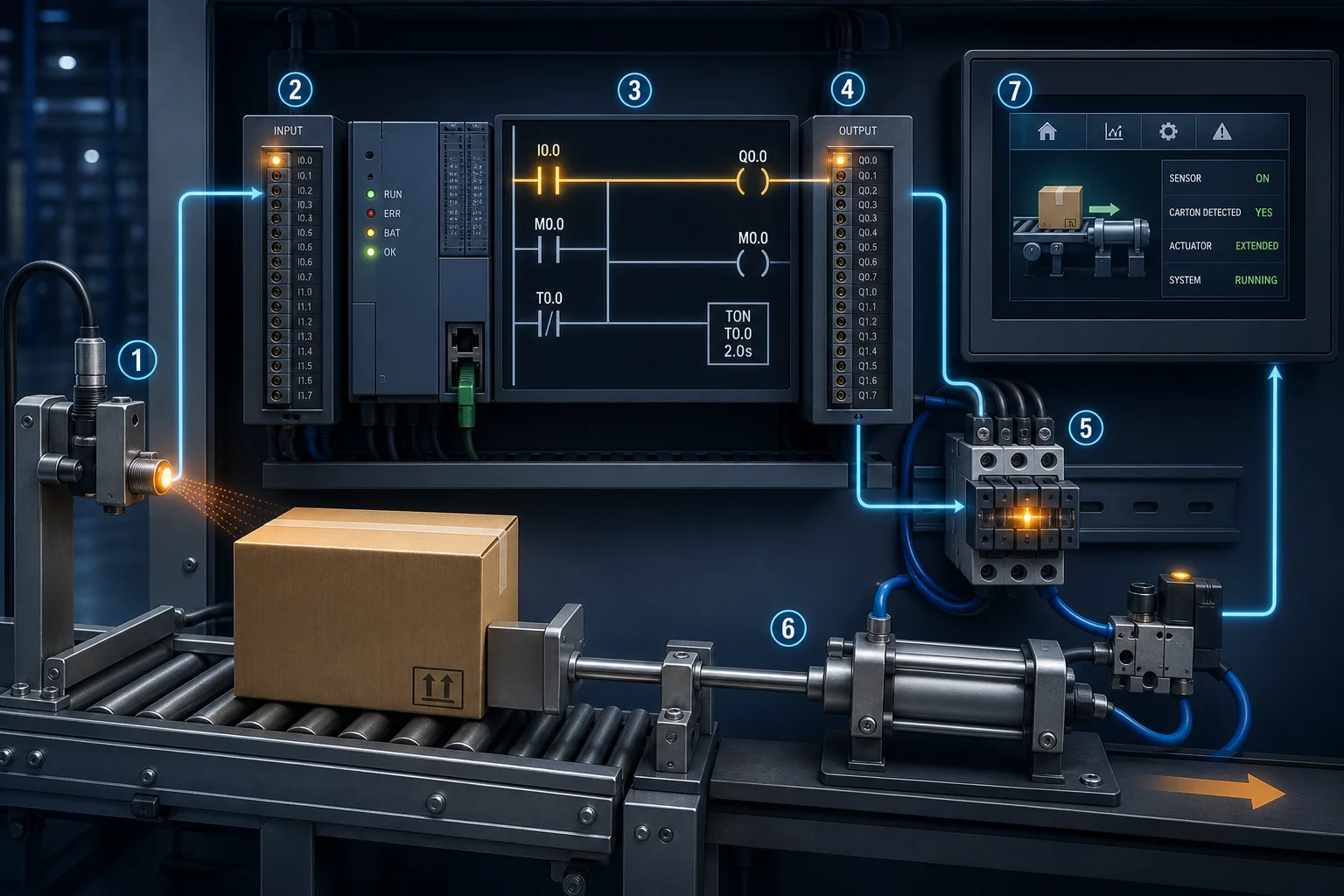
Industrial automation signal chain from carton sensor through PLC logic to contactor, cylinder and HMI
02Follow one event through the entire loop: detection, input, program decision, output, actuation and operator feedback.
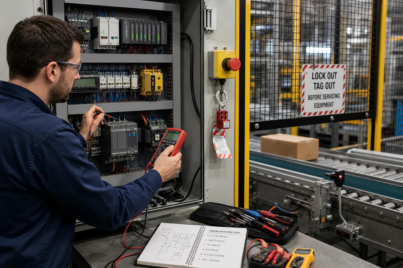
Technician safely fault-finding a conveyor control panel with a multimeter and lockout in place
03Use a safe, repeatable fault path across emergency stop, safety relay, PLC input, photoeye, starter, VFD and motor.
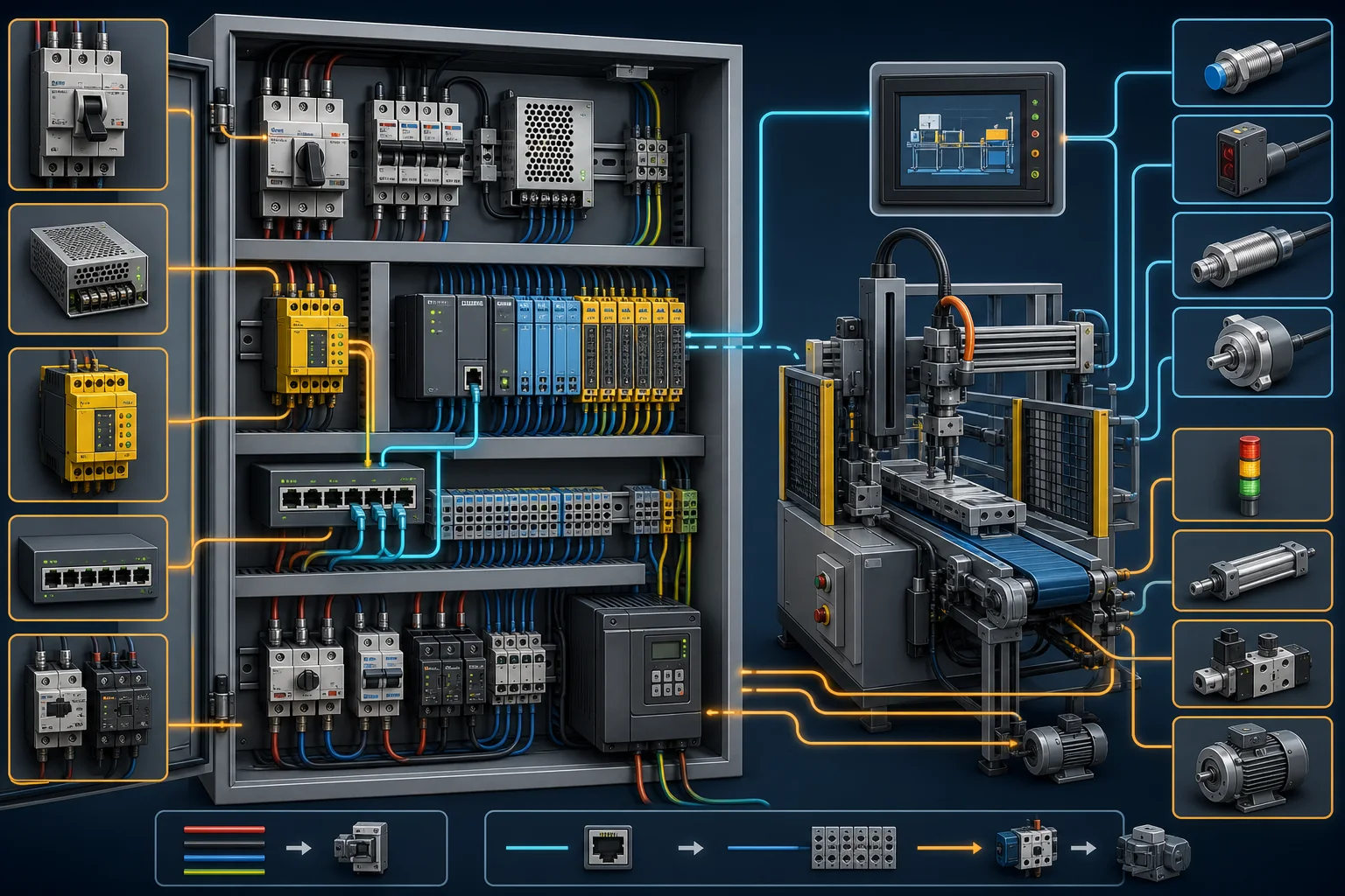
Industrial automation control-system cutaway showing PLC, safety, VFD, HMI, sensors and pneumatic actuator
04Recognise the hardware stack and understand which devices carry power, logic, safety and machine feedback.
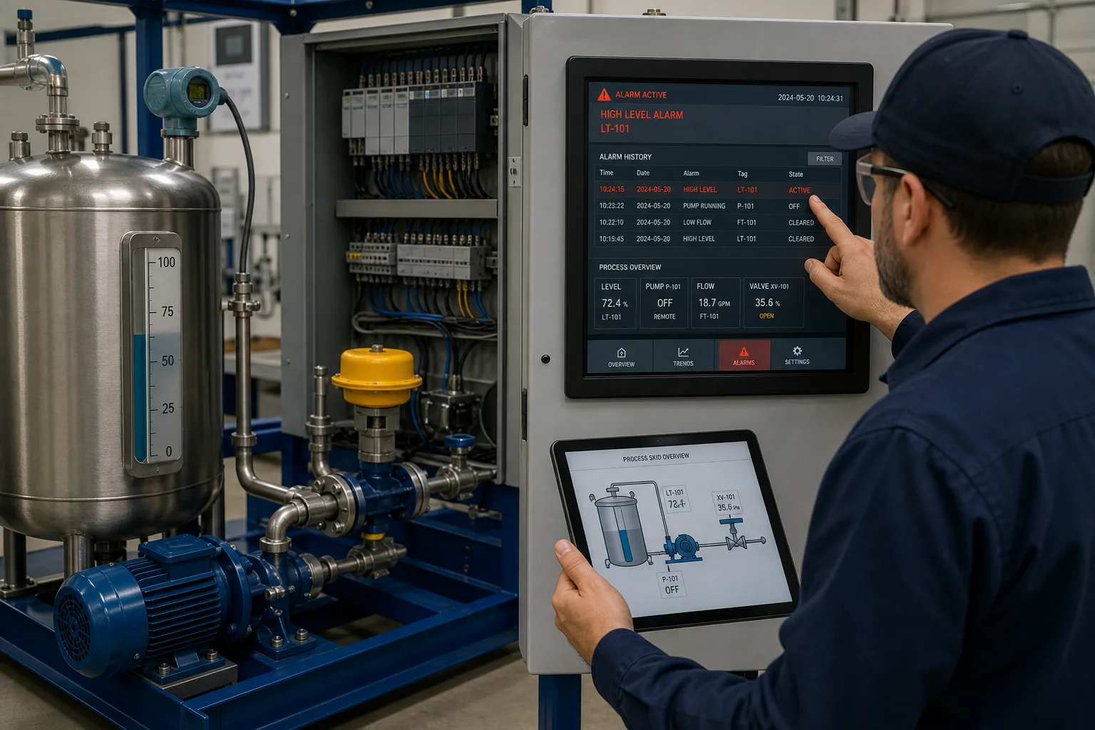
Automation technician comparing an HMI high-level alarm with a tank, pump and level instrument
05Treat an alarm as the beginning of a diagnosis by comparing HMI history, controller state and the physical process.
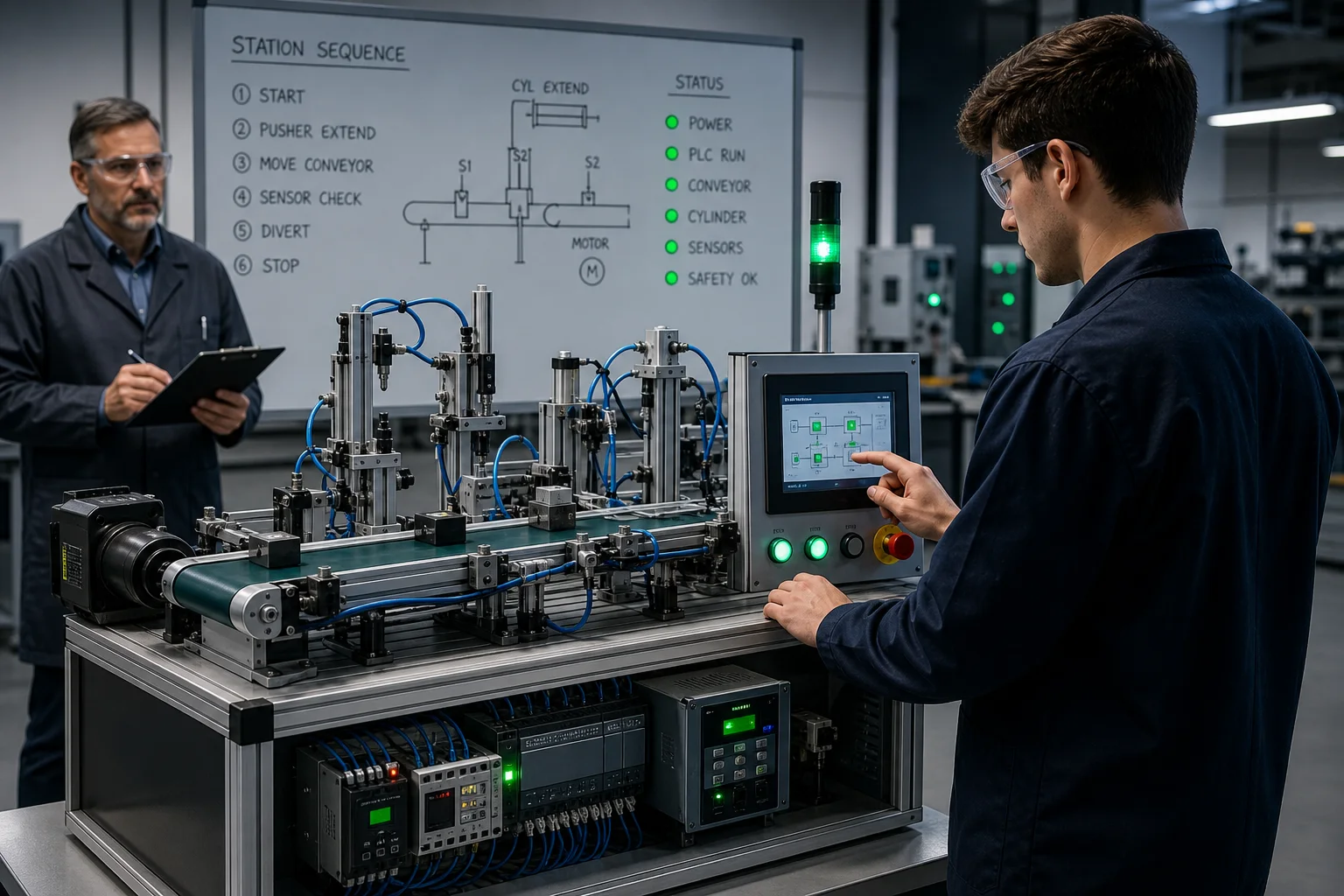
Learner completing an industrial automation skills assessment on a conveyor and pneumatic training system
06Prove the outcome on a working cell: sequence the equipment, handle abnormal states and recover deliberately.

What technicians actually practise

Control problems with process consequences

Every flagship combines PLC logic, dynamic machine state, failure conditions and deterministic grading. Learners must make the process safe—not just energise a coil.

PLC programming

Build ladder and Structured Text around scan-cycle behaviour, state, timing, counting, analog values and reusable sequence patterns.

Drives and motion

Commission contactors, VFD speed, direction, feedback, pneumatic motion and robot handshakes.

Instrumentation and process

Scale signals, manage alarms, control tanks, pumps, batches and utility equipment under changing process conditions.

3D systems thinking

Compose equipment, generate tags and validate full-floor material flow with the same reusable component library used by guided scenarios.

Complete guide · United States

What should industrial automation training teach?

Industrial automation training should teach a learner to understand, operate, program and troubleshoot a complete control system. A useful course connects electrical devices and machine behavior to PLC code instead of treating each topic as a separate vocabulary lesson.

What is industrial automation training?

It is job-focused technical training for the systems that sense a process, make control decisions and operate industrial equipment.

The field spans sensors, industrial wiring, programmable logic controllers, motor control, variable-frequency drives, pneumatic and process actuators, operator interfaces, networks, safety functions and fault diagnosis. The common thread is control: a technician must know what the machine was asked to do, which conditions permit it, which device should respond and what feedback proves that it happened.

Video can introduce those ideas, but competence requires practice. Learners need to change logic, toggle field conditions, observe the machine, create faults and restore normal operation without bypassing protection.

Which skills belong in the curriculum?

A complete curriculum moves from electrical and PLC fundamentals into machine sequencing, diagnostics and integrated systems.

  • Electrical control: 24 VDC I/O, relays, contactors, overloads, schematics and safe measurement.
  • PLC programming: scan cycle, contacts, coils, latches, timers, counters, analog values and state sequences.
  • Field devices: photoeyes, proximity sensors, limit switches, transmitters, valves, cylinders and motor feedback.
  • HMI and alarms: tag mapping, commands, permissives, alarm history and operator-safe recovery.
  • Drives and networks: VFD commands and feedback, device status, interlocks and industrial communications.
  • Troubleshooting: divide the system into input, logic, output and physical-response stages, then prove each stage.

What is the best learning order for a beginner?

Start with one input controlling one output, then add conditions only after the learner can predict the result of every PLC scan.

A strong sequence is switch and light, two-input AND/OR logic, start-stop seal-in, timers and counters, motor protection, sensor-driven conveyors, analog scaling, VFD control, alarms and multi-step processes. Every new concept should reuse earlier skills in a machine context. That spacing makes the learner retrieve the idea rather than merely recognise it.

The fastest route is explain, predict, build, run, diagnose and repeat. The platform’s guided mode supplies the next action and its purpose; learners can switch to independent mode once the support becomes unnecessary.

How do you judge whether online training is practical?

Look for observable tasks and objective outcomes, not lesson counts alone.

  • The learner edits executable PLC logic instead of watching a finished program.
  • Inputs, outputs and machine states change together while the program runs.
  • Assessments include abnormal conditions, failed permissives and recovery—not only normal operation.
  • Feedback identifies the failed requirement without silently completing the work for the learner.
  • Progress produces reusable evidence: completed scenarios, scores, code and assessed competencies.

Which US roles use these skills?

The skill set is most relevant to automation technicians, controls technicians, PLC technicians, industrial maintenance technicians and junior controls engineers.

Job titles vary by plant. Maintenance-focused roles usually diagnose and restore existing equipment; controls roles more often modify programs, commission equipment and integrate devices. Industrial machinery mechanics are a related US occupational group: the Bureau of Labor Statistics projects 13% employment growth from 2024 to 2034 and says increasing adoption of automated manufacturing machinery is expected to support demand.

Online simulation can accelerate the control-system portion of preparation, but it does not replace plant safety instruction, supervised electrical work, manufacturer-specific training or the on-the-job experience employers require.

Is a course certificate the same as professional certification?

No. A course certificate documents completed learning; professional certification is a separate, usually proctored validation from an industry body.

ISA distinguishes certificate programs from certification programs and offers credentials such as CCST and CAP. This platform provides practice and completion evidence, not an ISA or manufacturer credential. For a job application, pair any completion certificate with concrete proof: programs you wrote, faults you diagnosed and machine outcomes you can explain.

Scenario library

Start with the vertical. Build the transferable skills.

Browse all scenarios
Flagship

3D Conveyor Sort

Commission a visible conveyor, detection and diversion sequence using the live 3D machine.

3Dtracking
Open scenario

Motor Start / Stop

Build and verify the fundamental seal-in circuit with stop and overload protection.

motorladder
Open scenario

VFD Conveyor Speed

Coordinate analog speed demand, run permissives and drive feedback.

VFDanalog
Open scenario

Batch Mixer

Sequence fill, mix and drain phases with timers and process feedback.

processsequence
Open scenario

Robot Handshake

Prove request, busy, complete and fault states across a PLC/robot interface.

roboticsinterface
Open scenario

Light Curtain Muting

Reason about safe-state feedback and controlled material passage.

safetydiagnostics
Open scenario
Complete-floor practice

Build past the single machine.

Use 151 reusable objects to compose conveyors, work cells, process skids, warehouses, streets and utilities into one PLC-driven 3D floor.

151
reusable components
3
lazy-loadable packs
PLC
driven motion + faults

Public viewer is free. Guided 3D starts on Basic; composing and saving custom 3D scenes is Pro.

Live WebGL component viewer

151 real-time factory components

Load the interactive viewer when you are ready to orbit the models.

Loads 3D only after your click

Drag to orbit · scroll to zoom · choose any componentOpen full viewer ↗

Training outcomes

Evidence beyond course completion

Assignments can grade normal operation, unsafe demands, boundary conditions and recovery behavior against the same machine model.

  • Translate a machine requirement into an executable PLC sequence
  • Commission typed field feedback before enabling motion
  • Diagnose failed permissives and injected faults from observable state
  • Demonstrate recovery without bypassing the original protection

Scope, stated plainly

This is practical automation training software, not a replacement for manufacturer certification, machinery risk assessment, safety validation, process design or production commissioning procedures.

Team training details

Pilot with your standards

Map industrial automation practice to the equipment your technicians actually support

Use the existing labs immediately, then map assignments and pass criteria to the equipment, failure modes and competencies your team owns.

Complete controls-stack field guide

Industrial automation training: curriculum, practice and proof

Direct answer

Industrial automation training should connect field devices, electrical control, PLC execution, drives, HMI, networks and physical machine response. A useful program makes the learner predict behavior, run the system, diagnose a deliberately introduced fault and prove recovery with observable evidence.

This guide is written for apprentices, maintenance technicians, controls technicians, junior engineers and instructors who need one coherent route through the complete automation signal chain. The intended result is specific: the learner can trace a request from operator or sensor through input state, controller decision, output command, actuator motion and feedback—and can identify the first point where actual behavior disagrees with the expected sequence.

System map / 02

Six concepts that control the result

Treat these as connected checkpoints. Each checkpoint has an expected state, an observable state and a boundary to the next part of the system. That structure prevents a software indication from being mistaken for physical proof.

NODE 01observable

Signal chain

Identify the physical condition, sensor, input channel, program tag, logic decision, output channel, interface device, actuator and return feedback as one connected control loop.

NODE 02observable

PLC execution

Understand cyclic input sampling, program evaluation and output update well enough to predict timing, latching, priority and the effect of a changing field signal.

NODE 03observable

Electrical interface

Separate controller logic from relays, contactors, overloads, isolation, control voltage and the power circuit that actually carries load current.

NODE 04observable

Machine sequence

Describe operating states, permissives, transitions, timeouts, abnormal conditions and restart policy before choosing ladder or Structured Text instructions.

NODE 05observable

Operator information

Map commands, status, alarms and trends to real tags while keeping a clear distinction between a request, a controller decision and physical feedback.

NODE 06observable

Fault evidence

Preserve the first useful symptom, then divide the system at measurable boundaries instead of changing code, wiring and parameters simultaneously.

Procedure / 03

A six-step practice and commissioning workflow

Run the steps in order the first time. Later, the same structure becomes a diagnostic loop: define the expected condition, observe the boundary, interpret the difference and choose one proving action.

  1. 01

    Map the cell

    Name energy sources, controlled equipment, sensors, PLC I/O, HMI objects and networked devices.

    Evidence: A one-page signal map shows ownership and feedback for each controlled action.

    Avoid: Starting with software while the physical process remains undefined.

  2. 02

    Predict one scan

    Write the expected input, rung result and output state for a simple condition before running it.

    Evidence: Observed highlights and tags match the written prediction over repeated scans.

    Avoid: Treating one green rung as proof that the machine outcome is correct.

  3. 03

    Build normal operation

    Implement the smallest sequence that meets the observable requirement and safe stop policy.

    Evidence: Every transition has a cause, a destination and a feedback condition.

    Avoid: Adding timers to hide missing feedback or unclear state ownership.

  4. 04

    Exercise boundaries

    Test simultaneous commands, late feedback, stuck inputs, restart and maximum timing values.

    Evidence: The result is deterministic and the program reaches a defined safe or recoverable state.

    Avoid: Testing only the happy path from a fresh startup.

  5. 05

    Inject a fault

    Introduce one known fault and diagnose from symptom to the first disagreeing signal.

    Evidence: The evidence log records observation, hypothesis, proving action and result.

    Avoid: Replacing parts or editing code before establishing the failed boundary.

  6. 06

    Prove recovery

    Remove the cause, reset through the intended path and repeat the affected acceptance case.

    Evidence: Normal operation returns without hidden bypasses or unexpected automatic motion.

    Avoid: Confusing alarm acknowledgement with removal of the process cause.

Diagnostic matrix / 04

Symptoms, proving points and next actions

The table is a reasoning aid, not a parts-replacement chart. Preserve the initial symptom, inspect the named boundary and use the interpretation to choose the next controlled test. Site safety procedures and equipment manuals remain authoritative.

Diagnostic symptoms, inspection points, interpretations and next actions for Industrial automation training: curriculum, practice and proof
Observed symptomInspectInterpretationNext proving action
Input never changesField condition, device indication, wiring path, module channel and controller tagThe first missing transition identifies whether the fault is physical, electrical, configuration or program mapping.Prove voltage or state at the next approved boundary.
Logic true but output idleFinal output owner, inhibit conditions, output tag and module indicationA true intermediate bit is not the same as an energized physical output.Trace the exact final command and hardware channel.
Output active but no motionProtection, interface device, energy path, actuator and mechanical loadThe PLC may have completed its role while the power or physical layer failed.Move diagnosis beyond the controller without forcing the load.
Sequence stallsCurrent state, transition condition, timer, feedback and timeout branchA stalled sequence usually exposes missing feedback or an impossible transition condition.Prove each transition term separately.
Intermittent stopTimestamped command, permissive, feedback, alarm and network-quality historyThe first value to deviate is more useful than the final cascade of alarms.Capture a triggered pre/post-event window.
Unsafe restart riskRetentive state, command memory, physical position and restart policySoftware state can disagree with equipment state after power or communication returns.Require coherent feedback and a deliberate restart action.

Product evidence / 05

What the browser practice can actually demonstrate

The browser platform joins executable ladder or Structured Text to typed I/O, HMI state, electrical and process models, fault injection and deterministic scenario checks. That makes the curriculum inspectable instead of relying on video completion as evidence.

Where simulation stops

Simulation can build mental models and diagnostic discipline, but it cannot authorize live electrical work, validate a safety function, reproduce every controller firmware detail or replace supervised practice on the exact equipment used by an employer.

Commissioning notebook / 06

Six cases that turn the concepts into evidence

Use these as written briefs rather than click-through instructions. For every case, state the expected condition before acting, retain the first useful observation and explain why the final result proves the requirement. A different program or component choice can still be correct when it produces the same bounded behavior and evidence.

Case 01

predict → observe → prove

Prove signal chain

Engineering context. Identify the physical condition, sensor, input channel, program tag, logic decision, output channel, interface device, actuator and return feedback as one connected control loop. Begin with a written normal condition and identify which request, state, physical result or communication value will provide independent confirmation. Do not begin by changing the configuration; the initial state is part of the evidence and should remain reproducible.

Controlled setup. Use the “Map the cell” stage of the workflow: name energy sources, controlled equipment, sensors, PLC I/O, HMI objects and networked devices. The acceptance record should show this result: a one-page signal map shows ownership and feedback for each controlled action. Record initial conditions, the exact stimulus and the observation point so another learner can repeat the case without relying on your memory.

Fault challenge. Introduce or analyse “Input never changes” as one bounded deviation. Inspect field condition, device indication, wiring path, module channel and controller tag The working interpretation is that the first missing transition identifies whether the fault is physical, electrical, configuration or program mapping. The next proving action is to prove voltage or state at the next approved boundary. Change only one condition before observing the result, and preserve timestamps or measurements where timing matters.

Review and recovery. The most common trap here is starting with software while the physical process remains undefined. After restoring the cause, repeat the normal case and at least one stop, timeout, disconnect or restart boundary relevant to this topic. Remove temporary forces and bypasses, return the model to a known state and retain the evidence that both operation and recovery are deliberate.

Explain it aloud: What should I learn first in industrial automation? A defensible short answer is: Start with electrical state and one PLC input-to-output path. Add seal-in logic, timers, counters, motor control, sensors, analog values, HMI and networks only after you can predict each earlier layer.

Case 02

predict → observe → prove

Prove plc execution

Engineering context. Understand cyclic input sampling, program evaluation and output update well enough to predict timing, latching, priority and the effect of a changing field signal. Begin with a written normal condition and identify which request, state, physical result or communication value will provide independent confirmation. Do not begin by changing the configuration; the initial state is part of the evidence and should remain reproducible.

Controlled setup. Use the “Predict one scan” stage of the workflow: write the expected input, rung result and output state for a simple condition before running it. The acceptance record should show this result: observed highlights and tags match the written prediction over repeated scans. Record initial conditions, the exact stimulus and the observation point so another learner can repeat the case without relying on your memory.

Fault challenge. Introduce or analyse “Logic true but output idle” as one bounded deviation. Inspect final output owner, inhibit conditions, output tag and module indication The working interpretation is that a true intermediate bit is not the same as an energized physical output. The next proving action is to trace the exact final command and hardware channel. Change only one condition before observing the result, and preserve timestamps or measurements where timing matters.

Review and recovery. The most common trap here is treating one green rung as proof that the machine outcome is correct. After restoring the cause, repeat the normal case and at least one stop, timeout, disconnect or restart boundary relevant to this topic. Remove temporary forces and bypasses, return the model to a known state and retain the evidence that both operation and recovery are deliberate.

Explain it aloud: Can I learn automation completely online? A defensible short answer is: You can learn concepts, programming, sequencing and diagnostic reasoning online. Practical competence also requires supervised work with real energy, tools, wiring, equipment and site procedures.

Case 03

predict → observe → prove

Prove electrical interface

Engineering context. Separate controller logic from relays, contactors, overloads, isolation, control voltage and the power circuit that actually carries load current. Begin with a written normal condition and identify which request, state, physical result or communication value will provide independent confirmation. Do not begin by changing the configuration; the initial state is part of the evidence and should remain reproducible.

Controlled setup. Use the “Build normal operation” stage of the workflow: implement the smallest sequence that meets the observable requirement and safe stop policy. The acceptance record should show this result: every transition has a cause, a destination and a feedback condition. Record initial conditions, the exact stimulus and the observation point so another learner can repeat the case without relying on your memory.

Fault challenge. Introduce or analyse “Output active but no motion” as one bounded deviation. Inspect protection, interface device, energy path, actuator and mechanical load The working interpretation is that the PLC may have completed its role while the power or physical layer failed. The next proving action is to move diagnosis beyond the controller without forcing the load. Change only one condition before observing the result, and preserve timestamps or measurements where timing matters.

Review and recovery. The most common trap here is adding timers to hide missing feedback or unclear state ownership. After restoring the cause, repeat the normal case and at least one stop, timeout, disconnect or restart boundary relevant to this topic. Remove temporary forces and bypasses, return the model to a known state and retain the evidence that both operation and recovery are deliberate.

Explain it aloud: Is PLC programming enough for an automation technician? A defensible short answer is: No. PLC code is one layer. Technicians also need electrical control, field devices, actuators, HMI, drives, communications, safety boundaries and a disciplined measurement process.

Case 04

predict → observe → prove

Prove machine sequence

Engineering context. Describe operating states, permissives, transitions, timeouts, abnormal conditions and restart policy before choosing ladder or Structured Text instructions. Begin with a written normal condition and identify which request, state, physical result or communication value will provide independent confirmation. Do not begin by changing the configuration; the initial state is part of the evidence and should remain reproducible.

Controlled setup. Use the “Exercise boundaries” stage of the workflow: test simultaneous commands, late feedback, stuck inputs, restart and maximum timing values. The acceptance record should show this result: the result is deterministic and the program reaches a defined safe or recoverable state. Record initial conditions, the exact stimulus and the observation point so another learner can repeat the case without relying on your memory.

Fault challenge. Introduce or analyse “Sequence stalls” as one bounded deviation. Inspect current state, transition condition, timer, feedback and timeout branch The working interpretation is that a stalled sequence usually exposes missing feedback or an impossible transition condition. The next proving action is to prove each transition term separately. Change only one condition before observing the result, and preserve timestamps or measurements where timing matters.

Review and recovery. The most common trap here is testing only the happy path from a fresh startup. After restoring the cause, repeat the normal case and at least one stop, timeout, disconnect or restart boundary relevant to this topic. Remove temporary forces and bypasses, return the model to a known state and retain the evidence that both operation and recovery are deliberate.

Explain it aloud: How should automation skill be assessed? A defensible short answer is: Use observable tasks with initial conditions, expected outcomes, faults and recovery criteria. A quiz can test vocabulary; a scenario should test whether the learner can make and explain the system behavior.

Case 05

predict → observe → prove

Prove operator information

Engineering context. Map commands, status, alarms and trends to real tags while keeping a clear distinction between a request, a controller decision and physical feedback. Begin with a written normal condition and identify which request, state, physical result or communication value will provide independent confirmation. Do not begin by changing the configuration; the initial state is part of the evidence and should remain reproducible.

Controlled setup. Use the “Inject a fault” stage of the workflow: introduce one known fault and diagnose from symptom to the first disagreeing signal. The acceptance record should show this result: the evidence log records observation, hypothesis, proving action and result. Record initial conditions, the exact stimulus and the observation point so another learner can repeat the case without relying on your memory.

Fault challenge. Introduce or analyse “Intermittent stop” as one bounded deviation. Inspect timestamped command, permissive, feedback, alarm and network-quality history The working interpretation is that the first value to deviate is more useful than the final cascade of alarms. The next proving action is to capture a triggered pre/post-event window. Change only one condition before observing the result, and preserve timestamps or measurements where timing matters.

Review and recovery. The most common trap here is replacing parts or editing code before establishing the failed boundary. After restoring the cause, repeat the normal case and at least one stop, timeout, disconnect or restart boundary relevant to this topic. Remove temporary forces and bypasses, return the model to a known state and retain the evidence that both operation and recovery are deliberate.

Explain it aloud: Which PLC language should a beginner use? A defensible short answer is: Ladder logic is accessible for discrete relay-style control, while Structured Text is useful for data, calculations and explicit state logic. Transferable reasoning matters more than choosing one language forever.

Case 06

predict → observe → prove

Prove fault evidence

Engineering context. Preserve the first useful symptom, then divide the system at measurable boundaries instead of changing code, wiring and parameters simultaneously. Begin with a written normal condition and identify which request, state, physical result or communication value will provide independent confirmation. Do not begin by changing the configuration; the initial state is part of the evidence and should remain reproducible.

Controlled setup. Use the “Prove recovery” stage of the workflow: remove the cause, reset through the intended path and repeat the affected acceptance case. The acceptance record should show this result: normal operation returns without hidden bypasses or unexpected automatic motion. Record initial conditions, the exact stimulus and the observation point so another learner can repeat the case without relying on your memory.

Fault challenge. Introduce or analyse “Unsafe restart risk” as one bounded deviation. Inspect retentive state, command memory, physical position and restart policy The working interpretation is that software state can disagree with equipment state after power or communication returns. The next proving action is to require coherent feedback and a deliberate restart action. Change only one condition before observing the result, and preserve timestamps or measurements where timing matters.

Review and recovery. The most common trap here is confusing alarm acknowledgement with removal of the process cause. After restoring the cause, repeat the normal case and at least one stop, timeout, disconnect or restart boundary relevant to this topic. Remove temporary forces and bypasses, return the model to a known state and retain the evidence that both operation and recovery are deliberate.

Explain it aloud: Does a simulator replace a real PLC? A defensible short answer is: No. A browser simulator provides repeatable learning evidence. Target hardware is still required for exact timing, firmware, I/O electrical behavior, communications, safety and commissioning validation.

Answer surface / 07

Questions people ask about Industrial automation training

These concise answers define the operating, training and product boundaries most often missed in broad summaries. The full workflow and diagnostic table above provide the evidence behind them.

What should I learn first in industrial automation?

Start with electrical state and one PLC input-to-output path. Add seal-in logic, timers, counters, motor control, sensors, analog values, HMI and networks only after you can predict each earlier layer.

Can I learn automation completely online?

You can learn concepts, programming, sequencing and diagnostic reasoning online. Practical competence also requires supervised work with real energy, tools, wiring, equipment and site procedures.

Is PLC programming enough for an automation technician?

No. PLC code is one layer. Technicians also need electrical control, field devices, actuators, HMI, drives, communications, safety boundaries and a disciplined measurement process.

How should automation skill be assessed?

Use observable tasks with initial conditions, expected outcomes, faults and recovery criteria. A quiz can test vocabulary; a scenario should test whether the learner can make and explain the system behavior.

Which PLC language should a beginner use?

Ladder logic is accessible for discrete relay-style control, while Structured Text is useful for data, calculations and explicit state logic. Transferable reasoning matters more than choosing one language forever.

Does a simulator replace a real PLC?

No. A browser simulator provides repeatable learning evidence. Target hardware is still required for exact timing, firmware, I/O electrical behavior, communications, safety and commissioning validation.

How long should an automation course be?

Duration alone is weak evidence. Scope the course by competencies and require repeated successful performance across normal, boundary, fault and recovery cases.

What portfolio evidence helps an entry-level learner?

Keep tested programs, I/O lists, sequence descriptions, fault logs and short explanations of the observed machine result. Remove confidential plant information and state the simulator boundary.

Real industrial automation training footage

See this exact skill in the working simulator.

Watch the real browser product respond to the task on this page, then try the same practical workflow yourself. No slides, concept mockups, install, or credit card.

Try this in the browser
Industrial Automation Training — PLC, Wiring, HMI and Robotics