PLC Simulator
PLC field notessiemens

Siemens vs Allen-Bradley PLC: Which Should You Learn?

Siemens and Allen-Bradley are both industry-standard PLC platforms. Compare software, hardware, cost and job market to decide which one to learn first.

PLC Simulation Software9 min read

Siemens vs Allen-Bradley PLC comparison — software, cost and which to learn

If you are about to invest months learning a PLC platform, the choice between Siemens and Allen-Bradley feels enormous. Pick wrong and you have studied a system nobody near you hires for.

Short answer: learn the one your local job market uses. Both are mature, industry-standard platforms that you can build a career on. The real difference is geography and industry. Allen-Bradley (Rockwell Automation) dominates North America. Siemens dominates Europe and most of Asia. Other regions are mixed. So before you compare a single instruction, open the job listings within commuting distance of where you live and count which name comes up more. That count decides it more reliably than any feature table.

The good news: the concepts transfer almost completely. A timer, a seal-in rung, a latch, an analog scaling block — these work the same way on both. Once you know one platform well, the second is mostly a naming and tooling exercise, not a fresh start. This post compares them honestly so you know what you are actually choosing between.

The Same Logic, Two Houses

Both platforms implement the IEC 61131-3 languages — ladder, structured text, function block, and so on — so the underlying logic you write is recognisable across both. A motor start/stop seal-in is identical in shape regardless of vendor:

|--[Start]--+--[/Stop]--[/Overload]--( Motor )--|
|           |
|--[Motor]--+

The Start contact and the sealed-in Motor contact in parallel, the normally-closed Stop and Overload in series, driving the Motor coil. That rung is the same idea on a CompactLogix and on an S7-1500. What differs is the software you draw it in, how you name and address the I/O, and the hardware it runs on. Those differences are what the rest of this post covers.
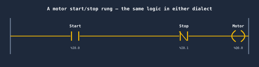
Motor start-stop seal-in rung that programs the same in Siemens and Allen-Bradley

If you want the deep syntax-level mapping — XIC/XIO/OTE vs Siemens absolute addressing, timer field names, block types — read PLC Dialects Compared: IEC 61131-3 vs Allen-Bradley vs Siemens. This post stays at the decision level.

Programming Software

This is the difference you will feel first and every day.

Allen-Bradley uses Studio 5000 Logix Designer for its modern controllers (and the legacy RSLogix 5000 for older ControlLogix, plus RSLogix 500 for the older MicroLogix/SLC line). Studio 5000 is a polished, tag-centric environment. You declare named tags, drag instructions onto rungs, and go online to watch live values. Many technicians find the project structure approachable. On projects that include an operator interface, Studio 5000 is complemented by FactoryTalk View for HMI design.

Siemens uses TIA Portal (Totally Integrated Automation Portal), a single environment that covers PLC programming, HMI design via WinCC, drives, and networking. TIA Portal is powerful and deeply integrated, but it is also large, opinionated, and has a steeper initial learning curve. Once it clicks, having the PLC, HMI, and drive configuration in one project is a genuine advantage.

Neither tool runs on a Mac natively and both are Windows-only, heavyweight installs. That matters when you are just trying to learn the basics — which is exactly the gap a browser-based simulator fills.

Addressing and Tag Conventions

Allen-Bradley is tag-based. You create named tags like Conveyor_Run or Tank_Level, give them a type, and optionally organise them into User-Defined Types (UDTs). You rarely think about physical memory addresses. This symbolic-first model is intuitive and is one reason beginners often find Allen-Bradley friendlier.

Siemens is symbolic too, but exposes the absolute address layer. A physical input is %I0.0, an output is %Q0.0, an internal flag is %M10.0. You give these symbolic names via the PLC tag table, but the absolute addresses are always present underneath. Structured data lives in Data Blocks (DBs) — for example "Motor_DB".Run — which is a powerful but more formal way to organise variables than AB's flat tag database.

In practice: Allen-Bradley hides the hardware addresses; Siemens keeps them in view. Both approaches are learnable; the Siemens model demands a little more up-front bookkeeping.

Languages and Instructions

Both support the IEC 61131-3 language set, but the naming and timer/counter models diverge.

  • Allen-Bradley uses proprietary TIMER and COUNTER data types. Timers are TON, TOF, and RTO (retentive on-delay), each a tag with fields like .PRE, .ACC, and .DN. Contacts and coils carry instruction labels: XIC, XIO, OTE, OTL, OTU. Reusable logic is packaged as Add-On Instructions (AOIs).
  • Siemens uses the IEC-standard timer blocks TON, TOF, and TP on modern S7-1200/S7-1500 controllers (older S7-300/400 code used proprietary S_ODT/S_OFFDT). For textual programming, Siemens offers SCL (Structured Control Language), its implementation of structured text, which is excellent for maths-heavy and algorithmic code. Reusable logic is packaged as Function Blocks (FBs) with instance data blocks.

Conceptually these are the same building blocks wearing different labels. Learn what an on-delay timer does and you have learned it on both platforms.

Hardware Families

Reference tableSwipe
Allen-Bradley (Rockwell)Siemens
Entry / compactMicro800 (Micro820/850/870)S7-1200
Mid to high performanceCompactLogixS7-1500
Large / processControlLogixS7-1500 (incl. redundant/PCS variants)
Legacy still in the fieldSLC 500, MicroLogix, PLC-5S7-300, S7-400

You will meet plenty of legacy hardware on real sites, so do not be surprised to see SLC 500 or S7-300 panels in service for years to come. New designs, though, are built on the modern families above.

Cost and Barrier to Entry

Here both platforms are, frankly, similar — and similarly painful for a self-learner. Genuine PLC hardware costs hundreds to thousands. The programming software is commercial, licensed, and not cheap; Studio 5000 and TIA Portal both gate their full functionality behind paid licenses, and obtaining a legitimate copy as an individual is awkward and expensive. There are limited free or trial editions, but they are time-limited or feature-restricted.

This is the wall most people hit. You have decided to learn, you know which platform your market uses, and then you discover the toolchain alone can cost more than a month's rent before you have written a single rung.

That barrier is exactly why we built a browser-based PLC simulator that supports IEC, Allen-Bradley-style, and Siemens-style dialects with no install and no license. You can write real ladder logic against a live machine model, switch dialects on the same scenario, and learn the concepts that transfer to whichever platform you end up employed on — all before you ever touch a licensed copy of Studio 5000 or TIA Portal.

Job Market

  • North America: Allen-Bradley is dominant across automotive, food and beverage, packaging, and general manufacturing. Most listings ask for Studio 5000 / RSLogix experience. If you are in the US or Canada, this is usually the safer first bet.
  • Europe: Siemens is dominant in machine building and across most industries. TIA Portal experience is the common requirement.
  • Asia, the Middle East, Africa, Australia: Mixed, often Siemens-leaning, but with strong regional and sector variation. Australia in particular sees both.
  • Process industries (oil and gas, water, chemicals) globally lean toward Siemens and DCS-style platforms, though Allen-Bradley has a strong process presence in North America.

Listings do not lie. Whatever the regional pattern, the postings in your area are the ground truth.

Side-by-Side Summary
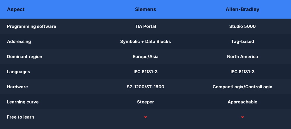
Siemens vs Allen-Bradley comparison table — software, addressing, region, hardware and learning curve

Reference tableSwipe
Allen-Bradley (Rockwell)Siemens
SoftwareStudio 5000 / RSLogixTIA Portal
Strongest regionNorth AmericaEurope, much of Asia
Addressing modelTag-based (hides addresses)Symbolic + absolute (%I, %Q, %M) + Data Blocks
TimersTON, TOF, RTO (proprietary types)IEC TON, TOF, TP (S7-1200/1500)
Structured textSupportedSCL (Siemens structured text)
Reusable logicAdd-On Instructions (AOIs)Function Blocks (FBs)
Entry hardwareMicro800S7-1200
Flagship hardwareControlLogix / CompactLogixS7-1500
Beginner friendlinessOften felt as gentlerSteeper start, deep integration payoff
Software costHigh, licensed, Windows-onlyHigh, licensed, Windows-only

There is no "better" column here. Both are excellent. The right answer is contextual.

Which Should You Learn First?

Match yourself to a situation:

  • You live in North America and want a job fast → Learn Allen-Bradley. The listings overwhelmingly favour it.
  • You live in Europe, or your local market is machine building → Learn Siemens / TIA Portal.
  • You have a specific employer or sector in mind → Learn whatever they run. Ask, or read their job postings. This beats every general rule.
  • You have no clear target yet, or you want maximum portability → Learn IEC 61131-3 fundamentals first (ladder contacts and coils, TON/CTU, seal-in, latches, scaling). Once those are second nature, adopting either vendor is a naming exercise. Tools like Codesys and OpenPLC are close to the IEC standard and free to experiment with.
  • You already know one platform and want the other → You are most of the way there. Focus on the tooling, the addressing model, and the instruction names — the logic carries over.

Whatever you choose, do not let the licensing wall stall you. Get the fundamentals solid in a free environment first, then specialise.

Practice Both, Free, In Your Browser

You do not need to pick a side to start learning today. Try the Allen-Bradley simulator dialect to get comfortable with tag-based addressing and XIC/XIO/OTE, then switch to the Siemens simulator dialect to see the same logic with %I/%Q addressing and Data Blocks. Writing the same scenario both ways is the fastest way to internalise what actually transfers between them.

Frequently asked questions

Is Siemens or Allen-Bradley better?

Neither is universally better — it depends on your region and industry. Allen-Bradley (Rockwell) dominates North American manufacturing, so it is the safer choice if you work or want to work in the US. Siemens dominates Europe and much of Asia and is strong in process industries. The best PLC to learn is the one used by employers in your local job market.

Why is Allen-Bradley so expensive?

Allen-Bradley hardware and the Studio 5000 software licensing carry a premium because Rockwell sells a tightly integrated ecosystem with strong North American support, distribution, and training. The cost is partly the hardware and partly the annual software subscription. For learning, you can practise Allen-Bradley-style ladder logic free in the browser without buying any Rockwell licence.

Which PLC is most used in the USA?

Allen-Bradley (Rockwell Automation) is the most widely deployed PLC brand in the United States, especially in discrete manufacturing, automotive, and packaging. Siemens has a large global footprint but a smaller US installed base. If you are job-hunting in North America, Allen-Bradley/Studio 5000 experience is usually the more in-demand skill.

Which is easier to learn, Siemens or Allen-Bradley?

Many beginners find Allen-Bradley's tag-based addressing and Studio 5000 slightly more approachable, while Siemens TIA Portal with Data Blocks has a steeper initial learning curve but is very powerful once mastered. Both implement IEC 61131-3, so the core ladder logic concepts transfer between them. Practising the same logic in both dialects is the fastest way to see the differences.

Can Siemens and Allen-Bradley PLCs communicate with each other?

Yes — they can exchange data over shared industrial protocols. Allen-Bradley speaks EtherNet/IP natively and Siemens speaks PROFINET, but both support common protocols such as Modbus TCP and OPC UA, and gateways exist to bridge EtherNet/IP and PROFINET. In a mixed plant you typically pick a common protocol or use a protocol converter to tie the two together.


Practice this yourself in the simulator — 3 scenarios free. No install. No license. No credit card. Write real ladder logic in IEC, Allen-Bradley-style, and Siemens-style dialects directly in your browser.

Try the simulator free →

ShareX / TwitterLinkedIn

From reading to running logic

Practice this yourself in the simulator

Start with guided PLC practice in your browser. No install and no credit card required.

Start practising free

Continue learning

Related field notes

All articles
allen bradley
rslogix

RSLogix 500 vs Studio 5000: What's the Difference?

RSLogix 500 programs SLC 500 and MicroLogix; Studio 5000 programs ControlLogix and CompactLogix. Compare hardware, addressing, and which to learn in 2026.

8 min read
certification
allen bradley

Allen-Bradley Certification: Routes, Cost and How to Prepare (2026)

An honest overview of Allen-Bradley and Rockwell certification in 2026: the Rockwell training routes, where ISA's CCST fits in, what it all costs, and a self-study plan to get certified faster on Studio 5000 and RSLogix.

8 min read
fundamentals
career

PLC Programming vs Traditional Programming: Python, Arduino & C

How PLC programming differs from Python, C and Arduino: the scan cycle, ladder vs relay logic, determinism, and whether a software dev can make the switch.

9 min read

Software evaluation field guide

Siemens versus Allen-Bradley PLC comparison: implementation, evidence and troubleshooting

Direct answer

Siemens versus Allen-Bradley PLC comparison becomes useful when it connects controller family, engineering-suite version, project organization, tag and data model, language, execution model, simulation path, diagnostics, licensing and deployment need with the same functional requirement through project setup, i/o mapping, reusable logic, timing, diagnostics, test workflow and target-hardware acceptance in each ecosystem, then proves one motor or sequence requirement implemented and behaviorally tested with identical initial conditions and pass criteria under normal, boundary, fault and recovery conditions. The objective is a repeatable engineering or learning result, not merely activity inside a page or tool.

This guide is written for learners, employers and technical buyers comparing two major PLC ecosystems without treating feature names as interchangeable. The intended result is specific: the reader can compare one representative job across project structure, tags, instructions, task or block execution, diagnostics, simulation and deployment evidence.

a controls technician completing a supervised practical assessment on generic PLC, motor-control and instrumentation equipment while studying Siemens and Allen-Bradley engineering workflow, execution and learning transfer
The training scene connects Siemens and Allen-Bradley engineering workflow, execution and learning transfer to a declared initial condition, observable boundaries, safe limits and repeatable acceptance evidence.

System map / 02

Six concepts that control the result

Treat these as connected checkpoints. Each checkpoint has an expected state, an observable state and a boundary to the next part of the system. That structure prevents a software indication from being mistaken for physical proof.

NODE 01observable

Define the operating contract

controller family, engineering-suite version, project organization, tag and data model, language, execution model, simulation path, diagnostics, licensing and deployment need. For Siemens and Allen-Bradley engineering workflow, execution and learning transfer, record the initial condition, actor, requested change, observable result and stopping condition before selecting a tool or implementation.

NODE 02observable

Map the evidence path

the same functional requirement through project setup, I/O mapping, reusable logic, timing, diagnostics, test workflow and target-hardware acceptance in each ecosystem. Separate request, internal state, output or service, physical or user-visible result and independent feedback so each boundary can be inspected.

NODE 03observable

Prove normal operation

one motor or sequence requirement implemented and behaviorally tested with identical initial conditions and pass criteria. Run more than one cycle from a known state and retain the values, timings or artifacts that demonstrate repeatability.

NODE 04observable

Exercise a boundary case

retentive state, first scan, task or block timing, data conversion, online edit, fault state, software version and project migration. Choose minimum, maximum, simultaneous, delayed or restart conditions that reveal assumptions hidden by the happy path.

NODE 05observable

Diagnose a controlled fault

a terminology, data, execution, instruction, configuration, simulation, diagnostic, license or deployment mismatch. Preserve the first symptom, divide the system at a measurable boundary and change one condition only after predicting the result.

NODE 06observable

Transfer and hand over

the chosen workflow verified in current official software, documentation and representative target hardware. Restore normal state, remove temporary changes, repeat affected checks and document which claims remain limited to the learning environment.

Procedure / 03

A six-step practice and commissioning workflow

Run the steps in order the first time. Later, the same structure becomes a diagnostic loop: define the expected condition, observe the boundary, interpret the difference and choose one proving action.

  1. 01

    Write the acceptance case

    Convert controller family, engineering-suite version, project organization, tag and data model, language, execution model, simulation path, diagnostics, licensing and deployment need into initial conditions, one stimulus and observable pass criteria.

    Evidence: Another person can repeat the case without guessing the intended result.

    Avoid: Using page completion or an animation as the acceptance criterion.

  2. 02

    Build the map

    Document the same functional requirement through project setup, i/o mapping, reusable logic, timing, diagnostics, test workflow and target-hardware acceptance in each ecosystem and name who owns each state or decision.

    Evidence: Every request and result has a source, destination and useful inspection point.

    Avoid: Using the same value as command, status and independent feedback.

  3. 03

    Run the baseline

    Apply one motor or sequence requirement implemented and behaviorally tested with identical initial conditions and pass criteria from a clean start and record the expected evidence.

    Evidence: Repeated runs produce the same bounded result.

    Avoid: Changing several parameters before a baseline exists.

  4. 04

    Challenge assumptions

    Test retentive state, first scan, task or block timing, data conversion, online edit, fault state, software version and project migration without changing the acceptance contract.

    Evidence: Limits, timing and restart behavior reach defined states.

    Avoid: Testing only one ideal sequence.

  5. 05

    Isolate one failure

    Introduce or analyse a terminology, data, execution, instruction, configuration, simulation, diagnostic, license or deployment mismatch and locate the first disagreement.

    Evidence: The proving action distinguishes the leading hypotheses.

    Avoid: Resetting, forcing or replacing before evidence is retained.

  6. 06

    Close the evidence loop

    Complete the chosen workflow verified in current official software, documentation and representative target hardware and repeat the affected regression cases.

    Evidence: An evaluation is complete when the same representative job is tested in each candidate and differences are recorded as evidence rather than inferred from feature labels.

    Avoid: Treating an acknowledged message or one successful rerun as handover.

Diagnostic matrix / 04

Symptoms, proving points and next actions

The table is a reasoning aid, not a parts-replacement chart. Preserve the initial symptom, inspect the named boundary and use the interpretation to choose the next controlled test. Site safety procedures and equipment manuals remain authoritative.

Diagnostic symptoms, inspection points, interpretations and next actions for Siemens versus Allen-Bradley PLC comparison: implementation, evidence and troubleshooting
Observed symptomInspectInterpretationNext proving action
The expected result is unclearRequirement, initial state, actor, stimulus, units and pass conditionThe evaluator, instructor and technical buyer may be solving different versions of the task.Rewrite one observable acceptance case before continuing.
Internal state changes but the outcome does notRequest, final owner, output or service boundary and independent feedbackA software or interface indication proves intent at one layer, not the complete outcome.Trace the first boundary after the changing state.
Normal case passes but an edge case failsLimits, timing, simultaneous events, reset and restart assumptionsThe implementation contains a hidden assumption exposed by the changed condition.Add the failed boundary as a permanent regression case.
The failure disappears after resetOriginal symptom, histories, diagnostics, timestamps and active causeReset changed evidence or state without proving the initiating cause.Reproduce under a controlled condition and preserve pre/post-event data.
Simulator and target disagreeModel boundary, software version, task timing, I/O behavior, data types and configurationA learning model and the intended target do not share one of the recorded assumptions.Reduce the case and verify against current target documentation.
The result cannot be explainedPrediction, observation, proving action, alternative hypotheses and limitationsActivity occurred but the evidence is not yet transferable or reviewable.Have the learner defend the signal path and repeat a changed case.

Product evidence / 05

What the browser practice can actually demonstrate

The public product surface exposes runnable examples, capability boundaries, pricing context and test-harness behavior that can be checked before a purchasing decision.

Where simulation stops

Availability, licensing, supported operating systems, controller features and training change; verify current official information for the exact product and region.

Commissioning notebook / 06

Six cases that turn the concepts into evidence

Use these as written briefs rather than click-through instructions. For every case, state the expected condition before acting, retain the first useful observation and explain why the final result proves the requirement. A different program or component choice can still be correct when it produces the same bounded behavior and evidence.

Case 01

predict → observe → prove

Prove define the operating contract

Engineering context. controller family, engineering-suite version, project organization, tag and data model, language, execution model, simulation path, diagnostics, licensing and deployment need. For Siemens and Allen-Bradley engineering workflow, execution and learning transfer, record the initial condition, actor, requested change, observable result and stopping condition before selecting a tool or implementation. Begin with a written normal condition and identify which request, state, physical result or communication value will provide independent confirmation. Do not begin by changing the configuration; the initial state is part of the evidence and should remain reproducible.

Controlled setup. Use the “Write the acceptance case” stage of the workflow: convert controller family, engineering-suite version, project organization, tag and data model, language, execution model, simulation path, diagnostics, licensing and deployment need into initial conditions, one stimulus and observable pass criteria. The acceptance record should show this result: another person can repeat the case without guessing the intended result. Record initial conditions, the exact stimulus and the observation point so another learner can repeat the case without relying on your memory.

Fault challenge. Introduce or analyse “The expected result is unclear” as one bounded deviation. Inspect requirement, initial state, actor, stimulus, units and pass condition The working interpretation is that the evaluator, instructor and technical buyer may be solving different versions of the task. The next proving action is to rewrite one observable acceptance case before continuing. Change only one condition before observing the result, and preserve timestamps or measurements where timing matters.

Review and recovery. The most common trap here is using page completion or an animation as the acceptance criterion. After restoring the cause, repeat the normal case and at least one stop, timeout, disconnect or restart boundary relevant to this topic. Remove temporary forces and bypasses, return the model to a known state and retain the evidence that both operation and recovery are deliberate.

Explain it aloud: Which is easier to learn, Siemens or Allen-Bradley? A defensible short answer is: Ease depends on local support and prior experience. Compare the same small job in each: project setup, tags, reusable code, online diagnosis, simulation and recovery.

Case 02

predict → observe → prove

Prove map the evidence path

Engineering context. the same functional requirement through project setup, I/O mapping, reusable logic, timing, diagnostics, test workflow and target-hardware acceptance in each ecosystem. Separate request, internal state, output or service, physical or user-visible result and independent feedback so each boundary can be inspected. Begin with a written normal condition and identify which request, state, physical result or communication value will provide independent confirmation. Do not begin by changing the configuration; the initial state is part of the evidence and should remain reproducible.

Controlled setup. Use the “Build the map” stage of the workflow: document the same functional requirement through project setup, i/o mapping, reusable logic, timing, diagnostics, test workflow and target-hardware acceptance in each ecosystem and name who owns each state or decision. The acceptance record should show this result: every request and result has a source, destination and useful inspection point. Record initial conditions, the exact stimulus and the observation point so another learner can repeat the case without relying on your memory.

Fault challenge. Introduce or analyse “Internal state changes but the outcome does not” as one bounded deviation. Inspect request, final owner, output or service boundary and independent feedback The working interpretation is that a software or interface indication proves intent at one layer, not the complete outcome. The next proving action is to trace the first boundary after the changing state. Change only one condition before observing the result, and preserve timestamps or measurements where timing matters.

Review and recovery. The most common trap here is using the same value as command, status and independent feedback. After restoring the cause, repeat the normal case and at least one stop, timeout, disconnect or restart boundary relevant to this topic. Remove temporary forces and bypasses, return the model to a known state and retain the evidence that both operation and recovery are deliberate.

Explain it aloud: Can Siemens and Allen-Bradley instructions be translated one for one? A defensible short answer is: Not reliably. Preserve the required behavior and retest state, timing, reset, task execution and restart assumptions in the target platform.

Case 03

predict → observe → prove

Prove prove normal operation

Engineering context. one motor or sequence requirement implemented and behaviorally tested with identical initial conditions and pass criteria. Run more than one cycle from a known state and retain the values, timings or artifacts that demonstrate repeatability. Begin with a written normal condition and identify which request, state, physical result or communication value will provide independent confirmation. Do not begin by changing the configuration; the initial state is part of the evidence and should remain reproducible.

Controlled setup. Use the “Run the baseline” stage of the workflow: apply one motor or sequence requirement implemented and behaviorally tested with identical initial conditions and pass criteria from a clean start and record the expected evidence. The acceptance record should show this result: repeated runs produce the same bounded result. Record initial conditions, the exact stimulus and the observation point so another learner can repeat the case without relying on your memory.

Fault challenge. Introduce or analyse “Normal case passes but an edge case fails” as one bounded deviation. Inspect limits, timing, simultaneous events, reset and restart assumptions The working interpretation is that the implementation contains a hidden assumption exposed by the changed condition. The next proving action is to add the failed boundary as a permanent regression case. Change only one condition before observing the result, and preserve timestamps or measurements where timing matters.

Review and recovery. The most common trap here is changing several parameters before a baseline exists. After restoring the cause, repeat the normal case and at least one stop, timeout, disconnect or restart boundary relevant to this topic. Remove temporary forces and bypasses, return the model to a known state and retain the evidence that both operation and recovery are deliberate.

Explain it aloud: What should I learn first about Siemens and Allen-Bradley engineering workflow, execution and learning transfer? A defensible short answer is: Start with the operating contract and evidence path: controller family, engineering-suite version, project organization, tag and data model, language, execution model, simulation path, diagnostics, licensing and deployment need, followed by the same functional requirement through project setup, i/o mapping, reusable logic, timing, diagnostics, test workflow and target-hardware acceptance in each ecosystem. Add advanced features only after the baseline is predictable.

Case 04

predict → observe → prove

Prove exercise a boundary case

Engineering context. retentive state, first scan, task or block timing, data conversion, online edit, fault state, software version and project migration. Choose minimum, maximum, simultaneous, delayed or restart conditions that reveal assumptions hidden by the happy path. Begin with a written normal condition and identify which request, state, physical result or communication value will provide independent confirmation. Do not begin by changing the configuration; the initial state is part of the evidence and should remain reproducible.

Controlled setup. Use the “Challenge assumptions” stage of the workflow: test retentive state, first scan, task or block timing, data conversion, online edit, fault state, software version and project migration without changing the acceptance contract. The acceptance record should show this result: limits, timing and restart behavior reach defined states. Record initial conditions, the exact stimulus and the observation point so another learner can repeat the case without relying on your memory.

Fault challenge. Introduce or analyse “The failure disappears after reset” as one bounded deviation. Inspect original symptom, histories, diagnostics, timestamps and active cause The working interpretation is that reset changed evidence or state without proving the initiating cause. The next proving action is to reproduce under a controlled condition and preserve pre/post-event data. Change only one condition before observing the result, and preserve timestamps or measurements where timing matters.

Review and recovery. The most common trap here is testing only one ideal sequence. After restoring the cause, repeat the normal case and at least one stop, timeout, disconnect or restart boundary relevant to this topic. Remove temporary forces and bypasses, return the model to a known state and retain the evidence that both operation and recovery are deliberate.

Explain it aloud: How do I practise Siemens and Allen-Bradley engineering workflow, execution and learning transfer effectively? A defensible short answer is: Use short cases with known initial conditions, a written prediction, one action and an observable result. Then alter a boundary or fault and explain why the evidence changed.

Case 05

predict → observe → prove

Prove diagnose a controlled fault

Engineering context. a terminology, data, execution, instruction, configuration, simulation, diagnostic, license or deployment mismatch. Preserve the first symptom, divide the system at a measurable boundary and change one condition only after predicting the result. Begin with a written normal condition and identify which request, state, physical result or communication value will provide independent confirmation. Do not begin by changing the configuration; the initial state is part of the evidence and should remain reproducible.

Controlled setup. Use the “Isolate one failure” stage of the workflow: introduce or analyse a terminology, data, execution, instruction, configuration, simulation, diagnostic, license or deployment mismatch and locate the first disagreement. The acceptance record should show this result: the proving action distinguishes the leading hypotheses. Record initial conditions, the exact stimulus and the observation point so another learner can repeat the case without relying on your memory.

Fault challenge. Introduce or analyse “Simulator and target disagree” as one bounded deviation. Inspect model boundary, software version, task timing, I/O behavior, data types and configuration The working interpretation is that a learning model and the intended target do not share one of the recorded assumptions. The next proving action is to reduce the case and verify against current target documentation. Change only one condition before observing the result, and preserve timestamps or measurements where timing matters.

Review and recovery. The most common trap here is resetting, forcing or replacing before evidence is retained. After restoring the cause, repeat the normal case and at least one stop, timeout, disconnect or restart boundary relevant to this topic. Remove temporary forces and bypasses, return the model to a known state and retain the evidence that both operation and recovery are deliberate.

Explain it aloud: What counts as proof of competence? A defensible short answer is: A repeatable artifact or system result plus an explanation of the signal path is stronger than time spent, screenshots or a copied answer. Physical competence requires separate supervised evidence.

Case 06

predict → observe → prove

Prove transfer and hand over

Engineering context. the chosen workflow verified in current official software, documentation and representative target hardware. Restore normal state, remove temporary changes, repeat affected checks and document which claims remain limited to the learning environment. Begin with a written normal condition and identify which request, state, physical result or communication value will provide independent confirmation. Do not begin by changing the configuration; the initial state is part of the evidence and should remain reproducible.

Controlled setup. Use the “Close the evidence loop” stage of the workflow: complete the chosen workflow verified in current official software, documentation and representative target hardware and repeat the affected regression cases. The acceptance record should show this result: an evaluation is complete when the same representative job is tested in each candidate and differences are recorded as evidence rather than inferred from feature labels. Record initial conditions, the exact stimulus and the observation point so another learner can repeat the case without relying on your memory.

Fault challenge. Introduce or analyse “The result cannot be explained” as one bounded deviation. Inspect prediction, observation, proving action, alternative hypotheses and limitations The working interpretation is that activity occurred but the evidence is not yet transferable or reviewable. The next proving action is to have the learner defend the signal path and repeat a changed case. Change only one condition before observing the result, and preserve timestamps or measurements where timing matters.

Review and recovery. The most common trap here is treating an acknowledged message or one successful rerun as handover. After restoring the cause, repeat the normal case and at least one stop, timeout, disconnect or restart boundary relevant to this topic. Remove temporary forces and bypasses, return the model to a known state and retain the evidence that both operation and recovery are deliberate.

Explain it aloud: Why test faults and restart behavior? A defensible short answer is: Because a terminology, data, execution, instruction, configuration, simulation, diagnostic, license or deployment mismatch or retentive state, first scan, task or block timing, data conversion, online edit, fault state, software version and project migration can expose assumptions that never appear during ideal startup and steady operation.

Answer surface / 07

Questions people ask about Siemens versus Allen-Bradley PLC comparison

These concise answers define the operating, training and product boundaries most often missed in broad summaries. The full workflow and diagnostic table above provide the evidence behind them.

Which is easier to learn, Siemens or Allen-Bradley?

Ease depends on local support and prior experience. Compare the same small job in each: project setup, tags, reusable code, online diagnosis, simulation and recovery.

Can Siemens and Allen-Bradley instructions be translated one for one?

Not reliably. Preserve the required behavior and retest state, timing, reset, task execution and restart assumptions in the target platform.

What should I learn first about Siemens and Allen-Bradley engineering workflow, execution and learning transfer?

Start with the operating contract and evidence path: controller family, engineering-suite version, project organization, tag and data model, language, execution model, simulation path, diagnostics, licensing and deployment need, followed by the same functional requirement through project setup, i/o mapping, reusable logic, timing, diagnostics, test workflow and target-hardware acceptance in each ecosystem. Add advanced features only after the baseline is predictable.

How do I practise Siemens and Allen-Bradley engineering workflow, execution and learning transfer effectively?

Use short cases with known initial conditions, a written prediction, one action and an observable result. Then alter a boundary or fault and explain why the evidence changed.

What counts as proof of competence?

A repeatable artifact or system result plus an explanation of the signal path is stronger than time spent, screenshots or a copied answer. Physical competence requires separate supervised evidence.

Why test faults and restart behavior?

Because a terminology, data, execution, instruction, configuration, simulation, diagnostic, license or deployment mismatch or retentive state, first scan, task or block timing, data conversion, online edit, fault state, software version and project migration can expose assumptions that never appear during ideal startup and steady operation.

Can browser practice replace official software or hardware?

No. It can build concepts and diagnostic reasoning. Exact firmware, I/O electrical behavior, networking, safety and commissioning require current official tools, documentation and target equipment.

How should progress be documented?

Keep the requirement, initial state, program or configuration, observed values, fault hypothesis, proving action, recovery result and a concise limitations statement.