PLC Simulator
PLC field notesscada

PLC and SCADA Training: Why the Pairing Sticks (And How to Learn Both in 16 Weeks)

PLC and SCADA are two different disciplines that have to be learned together to be useful in a modern plant. This guide explains where the boundary is, why most trainees fail at SCADA, and how to build both skills in 16 weeks using a browser-first simulator plus Ignition or Wonderware free tiers.

PLC Simulation Software11 min read

The PLC and SCADA training pairing that actually sticks

Search plc scada training and you'll notice two things: volumes are healthy (1,800/month for that exact phrase, another 1,700/month for scada training alone), and most of the top results conflate the two disciplines. That's the problem, and it's why most PLC+SCADA courses graduate people who can wire a tag but can't design an alarm strategy.

This guide sorts the two out, maps them to roles, and proposes a 16-week path that produces someone who is genuinely useful on a shop floor — not a certificate-holder with a vague warm feeling about "HMIs."

PLC and SCADA aren't the same skill

A PLC is a small, deterministic computer that reads field I/O and runs a control program every 20–50 ms. It controls things — valves, motors, heaters. It fails safely if you design it properly. The programming languages are IEC 61131-3 — ladder, structured text, function blocks.

SCADA stands for Supervisory Control And Data Acquisition. A SCADA system sits above the PLCs and does the jobs the PLC can't or shouldn't:

  • Visualisation for operators (the "HMI" — human-machine interface)
  • Historian that logs tag values for days, weeks, years
  • Alarming — knowing which of 5,000 tag changes matter, and who to notify
  • Reporting — shift reports, OEE, compliance summaries
  • Supervisory control — "run recipe B on tank 3 starting at 0400 tomorrow"

A PLC doesn't care what an operator sees. A SCADA system doesn't care about the scan cycle. They collaborate over a fieldbus (Modbus TCP, Ethernet/IP, Profinet, OPC UA) and each does one thing well.

People who learn one and not the other top out at a wall around 18 months into their career. People who learn both stay employable for decades.

Where PLC ends and SCADA begins
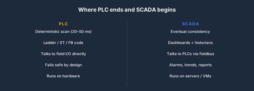
Where PLC ends and SCADA begins

This boundary causes more job-interview confusion than any other topic in industrial automation. The short version:

  • If it's a 20 ms decision, it belongs in the PLC. Turn the pump off if pressure exceeds setpoint. Close the e-stop loop on a limit switch fault. No operator action required.
  • If it's a 2-second decision, the PLC can do it but a SCADA recipe can trigger it. Start the CIP sequence at 0400.
  • If it's a 2-minute human decision, it's SCADA all the way. "Operator, acknowledge the high-temperature alarm on Tank 3 before the batch proceeds."

A good PLC programmer knows their code should never rely on SCADA staying online. A good SCADA engineer knows their screens should never depend on sub-second PLC-internal state. The fieldbus is the contract between them, and both sides should treat it as potentially lossy.

The stack, bottom to top
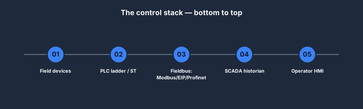
The control stack — bottom to top

Five layers, in increasing order of latency:

  1. Field devices — sensors, actuators, VFDs, valves. Physical. Talks DC 0–24 V or 4–20 mA current loops.
  2. PLC — the deterministic controller. Ladder + ST + occasional SFC.
  3. Fieldbus — Modbus TCP, Ethernet/IP, Profinet, Profibus. Takes PLC tag values and transports them to whoever asks.
  4. SCADA / historian — Ignition, Wonderware (now AVEVA), FactoryTalk View, iFIX, OpenSCADA. Logs tags, computes aggregates, raises alarms.
  5. HMI — operator screens, often running on the SCADA layer itself, sometimes dedicated panels.

Training either discipline in isolation leaves a blind spot. Training both together — with a concrete fieldbus exercise in the middle — produces engineers who understand how data flows end-to-end.

Why SCADA training fails in most courses

Three reasons, from our observation of trainee placement outcomes:

  1. Courses teach the software, not the design. You get 40 hours of "how to add a tag in Wonderware." What makes an operator screen useful — alarm rationalisation, trend grouping, shift-to-shift consistency — gets a one-hour slide at the end.
  2. No pairing with a PLC. You drag-and-drop a tag value onto a screen without writing the PLC code that produces that tag. You have no idea whether the value means anything, or what it fails safely to.
  3. No historian rigour. Trainees finish without ever discussing time-series compression, dead-bands, or why storing every scan-cycle value for 10,000 tags for 10 years will kill your database.

A SCADA engineer who's never written a PLC program is like a front-end developer who's never seen a database. It works until the first real problem.

A 16-week PLC + SCADA study plan
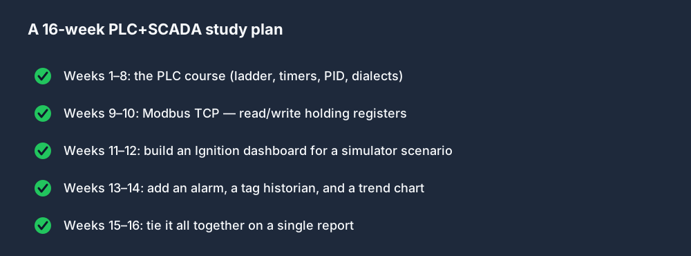
A 16-week PLC+SCADA study plan

Here's the sequence we'd recommend to anyone starting from scratch. 16 weeks, roughly 8 hours per week.

Weeks 1–8: the PLC half

Work through our complete PLC programming course at half-pace. You'll finish Weeks 1–4 (basics, ladder, timers, sequencing) and stop before PID.

By Week 8 you should have:

  • Written ten scenarios from scratch that pass auto-graded tests
  • A mental model of the scan cycle that explains every weird behaviour
  • A clean mental separation between what belongs in the PLC and what doesn't

Our Basic plan at USD 99/year covers this phase with all 40 scenarios unlocked and the auto-grader active.

Weeks 9–10: fieldbus

Your PLC needs to expose tags to a SCADA system. Modbus TCP is the simplest protocol and still the most common in the field for 2026.

  • Lesson: Modbus TCP in 45 minutes — function codes 3, 4, 6, 16 and what they map to
  • Exercise: expose four tags from the Motor Start/Stop scenario over a simulated Modbus server
  • Exercise: write a Python script that polls those tags every second and prints the values

You'll write the Modbus server as a tiny Node.js sidecar that listens on port 5502 and reads from the simulator's state API. The code is about 30 lines and we'll publish it in a follow-up post.

Weeks 11–12: your first dashboard

Install Ignition Maker Edition (free for non-commercial use) on a Raspberry Pi or a laptop VM. Point it at your Modbus server. Drag your first gauge onto a screen.

  • Lesson: Ignition tag browser and tag providers
  • Lesson: Templates and UDTs (User-Defined Types)
  • Exercise: build a one-screen dashboard for a bottling-line scenario with pump, valve, and tank-level indicators

At the end of this block you'll have a live dashboard showing state from the simulator's PLC program on one side of the screen and an Ignition HMI on the other. The data flows: browser-simulator → its API → Modbus server → Ignition tag → Ignition screen. You've built a real end-to-end control system in software.

Weeks 13–14: alarms and historians

A screen is not a SCADA system until it has alarms and a historian.

  • Lesson: Alarm rationalisation — the three questions to ask about every alarm
  • Lesson: Dead-bands, compression, and why storing every value is wrong
  • Exercise: add a high-high level alarm to the bottling-line dashboard. Make it acknowledge-required.
  • Exercise: wire the tank-level tag to the historian, generate a 15-minute trend chart

This is where most trainees discover that alarms are a design skill, not a software feature. You'll tune the alarm thresholds, set the dead-band, add the priority, and argue with yourself about whether to also flash the screen border.

Weeks 15–16: end-to-end

The final two weeks pull everything together into a shift report.

  • Build a second HMI screen: "yesterday" — shows a trend of the last 24 hours' tank levels with alarms overlaid
  • Write an Ignition report that emails itself every morning at 0600 with the previous day's events
  • Record a five-minute screen-capture walk-through of the whole system

Upload the walk-through to YouTube (unlisted if you prefer), paste the link into your CV. Hiring managers will watch 60 seconds of it and be sold.

Which SCADA to learn first

Four realistic choices in 2026:

  • Ignition (Inductive Automation) — our recommendation for first-time learners. Free Maker edition for learning, excellent documentation, free certification track. Growing market share.
  • Wonderware / AVEVA InTouch / System Platform — still the market leader in process industries. No free tier worth speaking of. Learn it on the job.
  • FactoryTalk View (Rockwell) — ubiquitous wherever Rockwell PLCs are. Tight integration with Studio 5000. Not a great free-learning option.
  • OpenSCADA / ScadaBR — open-source, useful for hobbyist and academic use, limited market recognition.

For self-study, Ignition Maker is the clear winner. For a career targeted at a specific shop, match the SCADA to whatever the shop runs.

FAQ

Is PLC or SCADA easier to learn?

PLC is harder to learn well but has a smaller surface area. SCADA has a huge surface area but most of it is configuration, not programming. If you learn them in sequence (PLC first), SCADA feels easier. If you try SCADA first, you'll hit a wall on tag semantics within two weeks.

Is there a free PLC and SCADA training online?

Yes. For the PLC half, one guided program runs without an account; a free account has 27 source-tagged practice records and the first six core lessons per dialect, subject to entitlement and rollout. For the SCADA half, Ignition's University of Ignition is free and excellent. Combine them with the 16-week plan above.

What's the best PLC-SCADA certification?

Inductive Automation's Ignition certifications are genuinely respected and free. ISA CAP covers both PLC and SCADA as part of broader automation. Vendor-specific SCADA certifications (Wonderware, FactoryTalk) are costly but gate specific jobs in their ecosystems. See our full PLC certification guide for the broader picture.

Can I get a SCADA job without PLC skills?

You can in the first five years of your career, but you'll plateau. The better SCADA engineers we've worked with can all read ladder logic well enough to tell when the problem is in the PLC vs their HMI.

How long does PLC and SCADA training take?

16 weeks at 8 hours per week if you do both. 8 weeks if you do PLC only. 8–12 weeks if you do SCADA only (and you'll regret skipping the PLC half eventually).

Where to start

  1. Sign up free for the simulator — 20 minutes in Traffic Light tells you if ladder thinking clicks.
  2. Follow our complete PLC course for Weeks 1–8.
  3. Install Ignition Maker. It takes 15 minutes.
  4. Come back to the Modbus exercise when you've finished Week 8.

Sixteen weeks, two disciplines, one employable skill set. Most of it is free; the fastest-paying part is USD 99/year. There isn't a better ROI in industrial automation training in 2026.
ShareX / TwitterLinkedIn

From reading to running logic

Practice this yourself in the simulator

Start with guided PLC practice in your browser. No install and no credit card required.

Start practising free

Continue learning

Related field notes

All articles
allen bradley
rockwell

Allen-Bradley Training in 2026: The Self-Study Path That Matches a USD 10,000 Classroom

A practical, self-study Allen-Bradley training path — RSLogix Micro to Studio 5000, Logix family, FactoryTalk View, EtherNet/IP — that takes 10–12 weeks, costs USD 99–249, and produces a portfolio a hiring manager can verify in 10 minutes.

13 min read
certification
career

PLC Certification Guide (2026): Which Ones Actually Help You Get Hired

A practitioner's guide to PLC certifications in 2026 — vendor certificates (Rockwell, Siemens), IEC 61131-3 proficiency, safety/SIL, and the portfolio-based alternatives that hiring managers increasingly prefer. What's worth paying for, what's a tax, and how to build a stack that actually signals competence.

13 min read
training
career

The Complete PLC Programming Course for 2026 (Self-Paced, Browser-First)

A 12-week PLC programming course that takes you from zero electrical background to writing production-grade ladder logic for Allen-Bradley, Siemens, and IEC PLCs. Self-paced, browser-based, no install, no vendor lock-in.

14 min read

Competency and practice field guide

PLC and SCADA training guide: implementation, evidence and troubleshooting

Direct answer

PLC and SCADA training guide becomes useful when it connects process requirement, plc tag contract, communications driver, polling or subscription, quality, timestamp, hmi object, command authority, alarm, trend and audit evidence with sensor through plc scaling, server mapping, transport, scada tag, quality and display plus operator command back through authorization and plc decision to feedback, then proves a known process change displays with correct value, unit, quality and time while a permitted command produces independently confirmed equipment response under normal, boundary, fault and recovery conditions. The objective is a repeatable engineering or learning result, not merely activity inside a page or tool.

This guide is written for automation learners and technicians connecting controller logic to supervisory displays, commands, alarms, trends, quality and operator procedures. The intended result is specific: the learner can trace one process value and one bounded command across PLC, communications and SCADA layers and diagnose stale or misleading presentation.

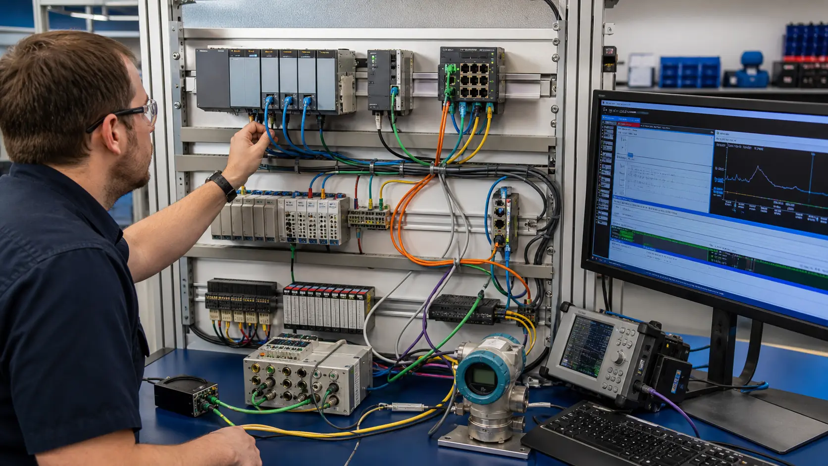
an industrial network diagnostics lab connecting generic controllers, distributed I/O, serial and Ethernet paths to protocol traces and process values while studying PLC-to-SCADA tags, alarms, commands and fault diagnosis
The scene keeps PLC-to-SCADA tags, alarms, commands and fault diagnosis connected to a declared operating condition, observable evidence, safe boundaries and a result another person can reproduce.

System map / 02

Six concepts that control the result

Treat these as connected checkpoints. Each checkpoint has an expected state, an observable state and a boundary to the next part of the system. That structure prevents a software indication from being mistaken for physical proof.

NODE 01observable

Define the operating contract

process requirement, PLC tag contract, communications driver, polling or subscription, quality, timestamp, HMI object, command authority, alarm, trend and audit evidence. For PLC-to-SCADA tags, alarms, commands and fault diagnosis, record the initial condition, actor, requested change, observable result and stopping condition before selecting a tool or implementation.

NODE 02observable

Map the evidence path

sensor through PLC scaling, server mapping, transport, SCADA tag, quality and display plus operator command back through authorization and PLC decision to feedback. Separate request, internal state, output or service, physical or user-visible result and independent feedback so each boundary can be inspected.

NODE 03observable

Prove normal operation

a known process change displays with correct value, unit, quality and time while a permitted command produces independently confirmed equipment response. Run more than one cycle from a known state and retain the values, timings or artifacts that demonstrate repeatability.

NODE 04observable

Exercise a boundary case

communication loss, stale value, bad quality, clock drift, unauthorized command, alarm flood, server restart, failover and mismatched scaling. Choose minimum, maximum, simultaneous, delayed or restart conditions that reveal assumptions hidden by the happy path.

NODE 05observable

Diagnose a controlled fault

a field, PLC, mapping, transport, server, timestamp, quality, display, authorization, command, alarm or feedback mismatch. Preserve the first symptom, divide the system at a measurable boundary and change one condition only after predicting the result.

NODE 06observable

Transfer and hand over

the application reviewed and tested in the production architecture with approved cybersecurity, alarm-management and operating controls. Restore normal state, remove temporary changes, repeat affected checks and document which claims remain limited to the learning environment.

Procedure / 03

A six-step practice and commissioning workflow

Run the steps in order the first time. Later, the same structure becomes a diagnostic loop: define the expected condition, observe the boundary, interpret the difference and choose one proving action.

  1. 01

    Write the acceptance case

    Convert process requirement, plc tag contract, communications driver, polling or subscription, quality, timestamp, hmi object, command authority, alarm, trend and audit evidence into initial conditions, one stimulus and observable pass criteria.

    Evidence: Another person can repeat the case without guessing the intended result.

    Avoid: Using page completion or an animation as the acceptance criterion.

  2. 02

    Build the map

    Document sensor through plc scaling, server mapping, transport, scada tag, quality and display plus operator command back through authorization and plc decision to feedback and name who owns each state or decision.

    Evidence: Every request and result has a source, destination and useful inspection point.

    Avoid: Using the same value as command, status and independent feedback.

  3. 03

    Run the baseline

    Apply a known process change displays with correct value, unit, quality and time while a permitted command produces independently confirmed equipment response from a clean start and record the expected evidence.

    Evidence: Repeated runs produce the same bounded result.

    Avoid: Changing several parameters before a baseline exists.

  4. 04

    Challenge assumptions

    Test communication loss, stale value, bad quality, clock drift, unauthorized command, alarm flood, server restart, failover and mismatched scaling without changing the acceptance contract.

    Evidence: Limits, timing and restart behavior reach defined states.

    Avoid: Testing only one ideal sequence.

  5. 05

    Isolate one failure

    Introduce or analyse a field, plc, mapping, transport, server, timestamp, quality, display, authorization, command, alarm or feedback mismatch and locate the first disagreement.

    Evidence: The proving action distinguishes the leading hypotheses.

    Avoid: Resetting, forcing or replacing before evidence is retained.

  6. 06

    Close the evidence loop

    Complete the application reviewed and tested in the production architecture with approved cybersecurity, alarm-management and operating controls and repeat the affected regression cases.

    Evidence: A learner completes the surface by explaining the result, passing a changed case and identifying what still requires supervised target-equipment practice.

    Avoid: Treating an acknowledged message or one successful rerun as handover.

Diagnostic matrix / 04

Symptoms, proving points and next actions

The table is a reasoning aid, not a parts-replacement chart. Preserve the initial symptom, inspect the named boundary and use the interpretation to choose the next controlled test. Site safety procedures and equipment manuals remain authoritative.

Diagnostic symptoms, inspection points, interpretations and next actions for PLC and SCADA training guide: implementation, evidence and troubleshooting
Observed symptomInspectInterpretationNext proving action
The expected result is unclearRequirement, initial state, actor, stimulus, units and pass conditionThe learner, instructor and assessor may be solving different versions of the task.Rewrite one observable acceptance case before continuing.
Internal state changes but the outcome does notRequest, final owner, output or service boundary and independent feedbackA software or interface indication proves intent at one layer, not the complete outcome.Trace the first boundary after the changing state.
Normal case passes but an edge case failsLimits, timing, simultaneous events, reset and restart assumptionsThe implementation contains a hidden assumption exposed by the changed condition.Add the failed boundary as a permanent regression case.
The failure disappears after resetOriginal symptom, histories, diagnostics, timestamps and active causeReset changed evidence or state without proving the initiating cause.Reproduce under a controlled condition and preserve pre/post-event data.
Simulator and target disagreeModel boundary, software version, task timing, I/O behavior, data types and configurationA learning model and the intended target do not share one of the recorded assumptions.Reduce the case and verify against current target documentation.
The result cannot be explainedPrediction, observation, proving action, alternative hypotheses and limitationsActivity occurred but the evidence is not yet transferable or reviewable.Have the learner defend the signal path and repeat a changed case.

Product evidence / 05

What the browser practice can actually demonstrate

The browser platform can retain programs, scenario results, attempts and observable machine state so practice is attached to evidence rather than seat time alone.

Where simulation stops

Browser training cannot validate a production SCADA system, cybersecurity architecture, alarm philosophy, historian, redundancy, role model or operating procedure.

Commissioning notebook / 06

Six cases that turn the concepts into evidence

Use these as written briefs rather than click-through instructions. For every case, state the expected condition before acting, retain the first useful observation and explain why the final result proves the requirement. A different program or component choice can still be correct when it produces the same bounded behavior and evidence.

Case 01

predict → observe → prove

Prove define the operating contract

Engineering context. process requirement, PLC tag contract, communications driver, polling or subscription, quality, timestamp, HMI object, command authority, alarm, trend and audit evidence. For PLC-to-SCADA tags, alarms, commands and fault diagnosis, record the initial condition, actor, requested change, observable result and stopping condition before selecting a tool or implementation. Begin with a written normal condition and identify which request, state, physical result or communication value will provide independent confirmation. Do not begin by changing the configuration; the initial state is part of the evidence and should remain reproducible.

Controlled setup. Use the “Write the acceptance case” stage of the workflow: convert process requirement, plc tag contract, communications driver, polling or subscription, quality, timestamp, hmi object, command authority, alarm, trend and audit evidence into initial conditions, one stimulus and observable pass criteria. The acceptance record should show this result: another person can repeat the case without guessing the intended result. Record initial conditions, the exact stimulus and the observation point so another learner can repeat the case without relying on your memory.

Fault challenge. Introduce or analyse “The expected result is unclear” as one bounded deviation. Inspect requirement, initial state, actor, stimulus, units and pass condition The working interpretation is that the learner, instructor and assessor may be solving different versions of the task. The next proving action is to rewrite one observable acceptance case before continuing. Change only one condition before observing the result, and preserve timestamps or measurements where timing matters.

Review and recovery. The most common trap here is using page completion or an animation as the acceptance criterion. After restoring the cause, repeat the normal case and at least one stop, timeout, disconnect or restart boundary relevant to this topic. Remove temporary forces and bypasses, return the model to a known state and retain the evidence that both operation and recovery are deliberate.

Explain it aloud: What should PLC and SCADA training cover? A defensible short answer is: Cover the complete path from field value and PLC logic through communications, quality, display, command, alarm, trend and operator response.

Case 02

predict → observe → prove

Prove map the evidence path

Engineering context. sensor through PLC scaling, server mapping, transport, SCADA tag, quality and display plus operator command back through authorization and PLC decision to feedback. Separate request, internal state, output or service, physical or user-visible result and independent feedback so each boundary can be inspected. Begin with a written normal condition and identify which request, state, physical result or communication value will provide independent confirmation. Do not begin by changing the configuration; the initial state is part of the evidence and should remain reproducible.

Controlled setup. Use the “Build the map” stage of the workflow: document sensor through plc scaling, server mapping, transport, scada tag, quality and display plus operator command back through authorization and plc decision to feedback and name who owns each state or decision. The acceptance record should show this result: every request and result has a source, destination and useful inspection point. Record initial conditions, the exact stimulus and the observation point so another learner can repeat the case without relying on your memory.

Fault challenge. Introduce or analyse “Internal state changes but the outcome does not” as one bounded deviation. Inspect request, final owner, output or service boundary and independent feedback The working interpretation is that a software or interface indication proves intent at one layer, not the complete outcome. The next proving action is to trace the first boundary after the changing state. Change only one condition before observing the result, and preserve timestamps or measurements where timing matters.

Review and recovery. The most common trap here is using the same value as command, status and independent feedback. After restoring the cause, repeat the normal case and at least one stop, timeout, disconnect or restart boundary relevant to this topic. Remove temporary forces and bypasses, return the model to a known state and retain the evidence that both operation and recovery are deliberate.

Explain it aloud: How is a SCADA fault different from a PLC fault? A defensible short answer is: SCADA can have mapping, quality, timing, server or display failures even while the PLC and process continue operating correctly.

Case 03

predict → observe → prove

Prove prove normal operation

Engineering context. a known process change displays with correct value, unit, quality and time while a permitted command produces independently confirmed equipment response. Run more than one cycle from a known state and retain the values, timings or artifacts that demonstrate repeatability. Begin with a written normal condition and identify which request, state, physical result or communication value will provide independent confirmation. Do not begin by changing the configuration; the initial state is part of the evidence and should remain reproducible.

Controlled setup. Use the “Run the baseline” stage of the workflow: apply a known process change displays with correct value, unit, quality and time while a permitted command produces independently confirmed equipment response from a clean start and record the expected evidence. The acceptance record should show this result: repeated runs produce the same bounded result. Record initial conditions, the exact stimulus and the observation point so another learner can repeat the case without relying on your memory.

Fault challenge. Introduce or analyse “Normal case passes but an edge case fails” as one bounded deviation. Inspect limits, timing, simultaneous events, reset and restart assumptions The working interpretation is that the implementation contains a hidden assumption exposed by the changed condition. The next proving action is to add the failed boundary as a permanent regression case. Change only one condition before observing the result, and preserve timestamps or measurements where timing matters.

Review and recovery. The most common trap here is changing several parameters before a baseline exists. After restoring the cause, repeat the normal case and at least one stop, timeout, disconnect or restart boundary relevant to this topic. Remove temporary forces and bypasses, return the model to a known state and retain the evidence that both operation and recovery are deliberate.

Explain it aloud: What should I learn first about PLC-to-SCADA tags, alarms, commands and fault diagnosis? A defensible short answer is: Start with the operating contract and evidence path: process requirement, plc tag contract, communications driver, polling or subscription, quality, timestamp, hmi object, command authority, alarm, trend and audit evidence, followed by sensor through plc scaling, server mapping, transport, scada tag, quality and display plus operator command back through authorization and plc decision to feedback. Add advanced features only after the baseline is predictable.

Case 04

predict → observe → prove

Prove exercise a boundary case

Engineering context. communication loss, stale value, bad quality, clock drift, unauthorized command, alarm flood, server restart, failover and mismatched scaling. Choose minimum, maximum, simultaneous, delayed or restart conditions that reveal assumptions hidden by the happy path. Begin with a written normal condition and identify which request, state, physical result or communication value will provide independent confirmation. Do not begin by changing the configuration; the initial state is part of the evidence and should remain reproducible.

Controlled setup. Use the “Challenge assumptions” stage of the workflow: test communication loss, stale value, bad quality, clock drift, unauthorized command, alarm flood, server restart, failover and mismatched scaling without changing the acceptance contract. The acceptance record should show this result: limits, timing and restart behavior reach defined states. Record initial conditions, the exact stimulus and the observation point so another learner can repeat the case without relying on your memory.

Fault challenge. Introduce or analyse “The failure disappears after reset” as one bounded deviation. Inspect original symptom, histories, diagnostics, timestamps and active cause The working interpretation is that reset changed evidence or state without proving the initiating cause. The next proving action is to reproduce under a controlled condition and preserve pre/post-event data. Change only one condition before observing the result, and preserve timestamps or measurements where timing matters.

Review and recovery. The most common trap here is testing only one ideal sequence. After restoring the cause, repeat the normal case and at least one stop, timeout, disconnect or restart boundary relevant to this topic. Remove temporary forces and bypasses, return the model to a known state and retain the evidence that both operation and recovery are deliberate.

Explain it aloud: How do I practise PLC-to-SCADA tags, alarms, commands and fault diagnosis effectively? A defensible short answer is: Use short cases with known initial conditions, a written prediction, one action and an observable result. Then alter a boundary or fault and explain why the evidence changed.

Case 05

predict → observe → prove

Prove diagnose a controlled fault

Engineering context. a field, PLC, mapping, transport, server, timestamp, quality, display, authorization, command, alarm or feedback mismatch. Preserve the first symptom, divide the system at a measurable boundary and change one condition only after predicting the result. Begin with a written normal condition and identify which request, state, physical result or communication value will provide independent confirmation. Do not begin by changing the configuration; the initial state is part of the evidence and should remain reproducible.

Controlled setup. Use the “Isolate one failure” stage of the workflow: introduce or analyse a field, plc, mapping, transport, server, timestamp, quality, display, authorization, command, alarm or feedback mismatch and locate the first disagreement. The acceptance record should show this result: the proving action distinguishes the leading hypotheses. Record initial conditions, the exact stimulus and the observation point so another learner can repeat the case without relying on your memory.

Fault challenge. Introduce or analyse “Simulator and target disagree” as one bounded deviation. Inspect model boundary, software version, task timing, I/O behavior, data types and configuration The working interpretation is that a learning model and the intended target do not share one of the recorded assumptions. The next proving action is to reduce the case and verify against current target documentation. Change only one condition before observing the result, and preserve timestamps or measurements where timing matters.

Review and recovery. The most common trap here is resetting, forcing or replacing before evidence is retained. After restoring the cause, repeat the normal case and at least one stop, timeout, disconnect or restart boundary relevant to this topic. Remove temporary forces and bypasses, return the model to a known state and retain the evidence that both operation and recovery are deliberate.

Explain it aloud: What counts as proof of competence? A defensible short answer is: A repeatable artifact or system result plus an explanation of the signal path is stronger than time spent, screenshots or a copied answer. Physical competence requires separate supervised evidence.

Case 06

predict → observe → prove

Prove transfer and hand over

Engineering context. the application reviewed and tested in the production architecture with approved cybersecurity, alarm-management and operating controls. Restore normal state, remove temporary changes, repeat affected checks and document which claims remain limited to the learning environment. Begin with a written normal condition and identify which request, state, physical result or communication value will provide independent confirmation. Do not begin by changing the configuration; the initial state is part of the evidence and should remain reproducible.

Controlled setup. Use the “Close the evidence loop” stage of the workflow: complete the application reviewed and tested in the production architecture with approved cybersecurity, alarm-management and operating controls and repeat the affected regression cases. The acceptance record should show this result: a learner completes the surface by explaining the result, passing a changed case and identifying what still requires supervised target-equipment practice. Record initial conditions, the exact stimulus and the observation point so another learner can repeat the case without relying on your memory.

Fault challenge. Introduce or analyse “The result cannot be explained” as one bounded deviation. Inspect prediction, observation, proving action, alternative hypotheses and limitations The working interpretation is that activity occurred but the evidence is not yet transferable or reviewable. The next proving action is to have the learner defend the signal path and repeat a changed case. Change only one condition before observing the result, and preserve timestamps or measurements where timing matters.

Review and recovery. The most common trap here is treating an acknowledged message or one successful rerun as handover. After restoring the cause, repeat the normal case and at least one stop, timeout, disconnect or restart boundary relevant to this topic. Remove temporary forces and bypasses, return the model to a known state and retain the evidence that both operation and recovery are deliberate.

Explain it aloud: Why test faults and restart behavior? A defensible short answer is: Because a field, plc, mapping, transport, server, timestamp, quality, display, authorization, command, alarm or feedback mismatch or communication loss, stale value, bad quality, clock drift, unauthorized command, alarm flood, server restart, failover and mismatched scaling can expose assumptions that never appear during ideal startup and steady operation.

Answer surface / 07

Questions people ask about PLC and SCADA training guide

These concise answers define the operating, training and product boundaries most often missed in broad summaries. The full workflow and diagnostic table above provide the evidence behind them.

What should PLC and SCADA training cover?

Cover the complete path from field value and PLC logic through communications, quality, display, command, alarm, trend and operator response.

How is a SCADA fault different from a PLC fault?

SCADA can have mapping, quality, timing, server or display failures even while the PLC and process continue operating correctly.

What should I learn first about PLC-to-SCADA tags, alarms, commands and fault diagnosis?

Start with the operating contract and evidence path: process requirement, plc tag contract, communications driver, polling or subscription, quality, timestamp, hmi object, command authority, alarm, trend and audit evidence, followed by sensor through plc scaling, server mapping, transport, scada tag, quality and display plus operator command back through authorization and plc decision to feedback. Add advanced features only after the baseline is predictable.

How do I practise PLC-to-SCADA tags, alarms, commands and fault diagnosis effectively?

Use short cases with known initial conditions, a written prediction, one action and an observable result. Then alter a boundary or fault and explain why the evidence changed.

What counts as proof of competence?

A repeatable artifact or system result plus an explanation of the signal path is stronger than time spent, screenshots or a copied answer. Physical competence requires separate supervised evidence.

Why test faults and restart behavior?

Because a field, plc, mapping, transport, server, timestamp, quality, display, authorization, command, alarm or feedback mismatch or communication loss, stale value, bad quality, clock drift, unauthorized command, alarm flood, server restart, failover and mismatched scaling can expose assumptions that never appear during ideal startup and steady operation.

Can browser practice replace official software or hardware?

No. It can build concepts and diagnostic reasoning. Exact firmware, I/O electrical behavior, networking, safety and commissioning require current official tools, documentation and target equipment.

How should progress be documented?

Keep the requirement, initial state, program or configuration, observed values, fault hypothesis, proving action, recovery result and a concise limitations statement.