
PLC Simulator
PLC field notessafety

Safety PLCs for Beginners: What They Do Differently (And When You Need One)

An introduction to safety PLCs for standard-PLC engineers — what makes a controller 'safety-rated,' what SIL levels actually mean, and where the boundary is between a safety function and normal control. Covers GuardLogix, S7-1500F, Omron NX-Safety, and why you can't just code your way to SIL 2.

PLC Simulation Software9 min read

Safety PLCs for beginners — what they do differently

A safety PLC is not a faster or more expensive version of a regular PLC. It's a fundamentally different kind of controller, designed and certified to guarantee deterministic failure behaviour when human lives are on the line. If your machine has an emergency stop, a light curtain, a guard door interlock, or two-hand controls — and any of them are rated higher than SIL 1 — a safety PLC is mandatory.

This post is the orientation for a PLC engineer who's never worked with safety. For the bigger certification picture, see our PLC certification guide.

What makes a PLC "safety-rated"

Three things, roughly:

  1. Redundant hardware. Safety PLCs run dual processors that execute the same code in lockstep and compare results every scan. Disagreement = fault = safe state. A standard PLC has one processor; if it glitches, the output state is undefined.
  2. Certified firmware. The firmware has been audited by TÜV (or equivalent) against IEC 61508. Every behaviour is traceable. A standard PLC's firmware is written to be correct; a safety PLC's firmware is written to be provably correct.
  3. Certified function blocks. You can't program a safety function with arbitrary ladder. You use vendor-provided, TÜV-certified blocks: Safety_ESTOP, Safety_LightCurtain, Safety_TwoHand. You can wire them together; you can't write your own.

If any of the three is missing, it's not a safety PLC — it's a regular PLC marketed to fool procurement.

SIL levels in plain English
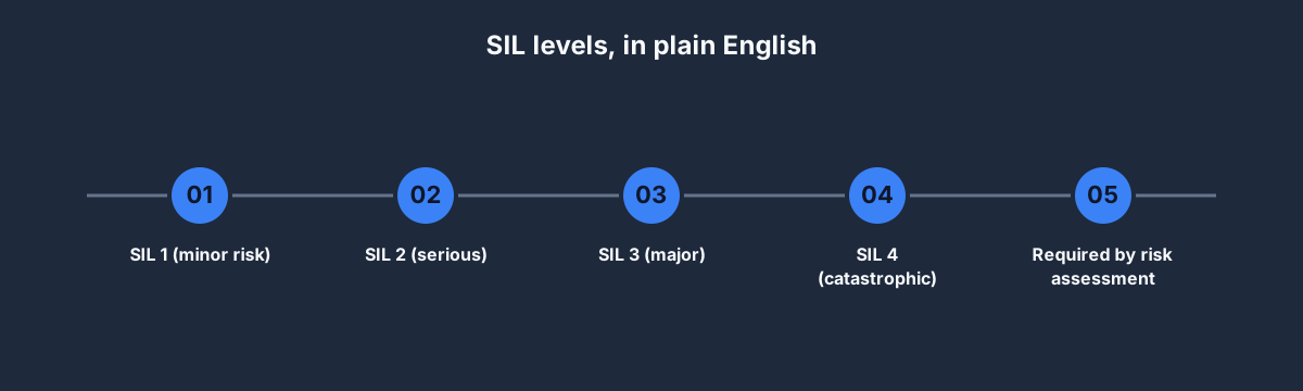
SIL levels, in plain English

SIL (Safety Integrity Level) quantifies how reliable a safety function must be, from 1 (lowest) to 4 (highest).

  • SIL 1 — acceptable failure rate 10⁻² to 10⁻¹ per year. Minor risks (bruises, brief injury).
  • SIL 2 — 10⁻³ to 10⁻² per year. Serious injuries.
  • SIL 3 — 10⁻⁴ to 10⁻³ per year. Major injuries, possible single fatality.
  • SIL 4 — 10⁻⁵ to 10⁻⁴ per year. Catastrophic. Almost never seen in factory automation; reserved for nuclear, railway signalling, aerospace.

For manufacturing and industrial automation, SIL 2 and SIL 3 are the common targets. You don't pick SIL; a formal risk assessment (per ISO 13849, ISO 12100, or sector-specific standards) pins the number.

Critical: you cannot "code your way" to a SIL level. SIL is a property of the whole loop — sensor, controller, logic, actuator — not just the code. A SIL 3 function needs SIL 3 sensors, a SIL 3-certified PLC, SIL 3 logic configuration, and a SIL 3 actuator. One weak link drags the whole loop down.

Standard PLC vs safety PLC
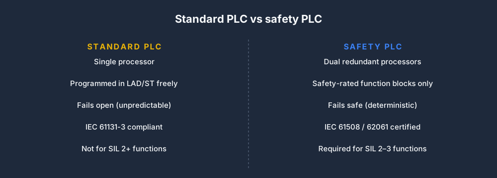
Standard PLC vs safety PLC

Reference tableSwipe
Standard PLCSafety PLC
CostUSD 500–5,000USD 3,000–15,000
ProgrammingFree-form LAD/ST/SFCCertified blocks only
FirmwareNon-certifiedTÜV IEC 61508 certified
RedundancyNoneDual processor
Failure modeUndefinedProvably safe
Typical SILUp to 1 (with caveats)SIL 2 or SIL 3

Most modern safety PLCs are "F-variants" of standard controllers — a GuardLogix is a ControlLogix with safety features, an S7-1500F is an S7-1500 with safety features. You can run standard and safety code on the same controller. The safety parts execute under stricter rules; the standard parts execute normally.

Where a safety PLC is non-negotiable

Where a safety PLC is non-negotiable

Five canonical applications that almost always require safety-rated control:

  • Emergency stop loops. A SIL 2–3 E-stop cannot be a standard input into a standard PLC. It has to go through a safety relay or contactor circuit or a safety PLC with dual-channel monitoring.
  • Light curtain monitoring. Light curtains detect bodies entering a hazard zone. Always SIL 2+ in practice.
  • Two-hand controls. Both hands on buttons = machine runs; release either = machine stops. The logic must be deterministic and fail-safe.
  • Guard door interlocks. Door closed = machine can run; door open = machine in safe state. Standard-PLC interlocks fail randomly and kill people.
  • Muting and bypass. Temporarily ignoring a safety device (e.g. to let product pass through a light curtain) must be its own safety function.

Our safety scenarios — Two-Hand Control, Light Curtain Muting, Safety Mat Monitor, E-Stop & Reset — cover the patterns vendor-agnostically. Practising them in a simulator won't certify you but does build the right intuition.

Named safety PLCs you'll encounter

  • Rockwell GuardLogix — the safety variant of ControlLogix. SIL 3-capable. Programmed in Studio 5000 with safety tasks and certified AOIs.
  • Siemens S7-1500F, S7-1200F, ET 200SP F-CPU — F-variants across the S7 range. SIL 3. Programmed in TIA Portal with F-blocks.
  • Omron NX-Safety — NX1 chassis with safety modules. SIL 3.
  • Pilz PSS / PNOZmulti — safety-specialist vendor. Pilz specialises in pure safety; pairs with regular controllers via fieldbus.
  • Banner SC and Sick Flexi Soft — smaller safety controllers for standalone safety functions without a full safety PLC.

If your project's risk assessment pins a SIL 3 function, any of the first three can carry it. Pick the one that matches the rest of your controls stack.

How to get started with safety PLCs

  1. Read ISO 13849 and IEC 62061. Not optional. These are the machinery safety standards; every safety function is built against their requirements.
  2. Complete a TÜV Functional Safety Engineer (FSE) course if you want to work in this specialty professionally. USD 2,500–3,500, 3–5 days. Widely recognised.
  3. Practise the canonical patterns in a browser simulator. Our safety scenarios aren't TÜV-certified but build the intuition cheaply.
  4. Get on-the-job experience. There's no substitute. Shadow a certified engineer on a real SIL 2 project before you own one yourself.

Don't try to do safety engineering from a textbook without experience. It's one of the few areas where "move fast and learn" is genuinely the wrong approach.

Common misconceptions

  • "If I write my ladder carefully, I don't need a safety PLC." Wrong. Safety certification is about provability, not quality. You can write perfect code on a non-certified PLC and it still isn't SIL 2.
  • "A safety relay is a cheap safety PLC." Not a PLC, but can be enough. Safety relays handle single functions (one E-stop, one door). Safety PLCs handle many. Use relays for small machines, safety PLCs when you have three or more safety functions.
  • "Adding more redundancy makes it safer." Only if the redundancy is diverse. Two identical PLCs running identical code have the same bugs. Safety redundancy requires diverse implementation.
  • "Muting a light curtain is just a timer." No. Muting must itself be a safety function, with its own SIL rating and its own certified logic.

FAQ

What is the difference between a safety PLC and a regular PLC?

Redundant hardware, certified firmware, certified function blocks, and IEC 61508-traceable behaviour. A regular PLC isn't allowed to perform SIL 2 or SIL 3 safety functions no matter how carefully you code it.

How much does a safety PLC cost?

USD 3,000–15,000 for a typical SIL 2–3 system. F-variant modules cost more than standard equivalents; development time is longer; audit effort is higher. Total cost is usually 2–3× a standard-PLC install.

Do I need a safety PLC for an emergency stop?

For any E-stop rated above SIL 1 (most industrial E-stops), yes. Cheaper alternative for simple machines: a dedicated safety relay.

What PLC certification should a safety engineer have?

TÜV FSE (Functional Safety Engineer) is the broadest credential. ISA's CAP covers it as part of the wider automation certification. See our PLC certification post for the bigger picture.

Can I learn safety PLC programming in a simulator?

The patterns yes, the certification no. Our safety scenarios cover E-stop reset, two-hand control, light curtain muting, and safety mat monitoring. For actual safety work, follow with formal training and supervised on-the-job experience.

Where to start

  1. Read this post twice.
  2. Work through our Two-Hand Control scenario and Light Curtain Muting in the simulator.
  3. If safety is a target specialty, enrol in a TÜV FSE course.
  4. Get project experience under a certified senior engineer before owning safety decisions.

Safety PLCs are one of the highest-paid PLC specialties. They're also the one where wrong answers have the highest stakes. Learn carefully.
ShareX / TwitterLinkedIn

From reading to running logic

Practice this yourself in the simulator

Start with guided PLC practice in your browser. No install and no credit card required.

Start practising free

Continue learning

Related field notes

All articles
siemens
tia portal

TIA Portal Tutorial: Your First S7-1200 Program in One Sitting

A complete TIA Portal tutorial for newcomers — install, configure an S7-1200, write a start/stop rung in LAD, add a small SCL function block, and run everything in PLCSIM. No hardware required, 21-day trial is enough.

9 min read
beginner
debugging

Top 5 PLC Programming Mistakes Beginners Make (and How to Fix Them)

The five most common PLC programming mistakes beginners make: wrong contact type, scan-cycle order bugs, latch coil misuse, timer preset errors, and ignoring edge detection. With examples.

8 min read
beginner
fundamentals

PLC Programming for Absolute Beginners (2026 Roadmap)

A gentle, non-jargon guide to PLC programming for people with no electrical background. Covers the scan cycle, your first rung, the five things that will confuse you, and a four-week starter plan that you can follow in a browser without installing anything.

9 min read

Technical reference and worked-example guide

Safety PLCs for beginners: implementation, evidence and troubleshooting

Direct answer

Safety PLCs for beginners becomes useful when it connects hazard, safety function, required performance, safe state, demand rate, input subsystem, logic solver, output subsystem, diagnostics, reset, bypass, verification and validation with hazardous event through protective device, safety input, certified logic, safety output, final element, energy or motion reduction and measured safe outcome, then proves one declared safety demand produces the specified safe state and restart remains inhibited until all defined conditions and deliberate action exist under normal, boundary, fault and recovery conditions. The objective is a repeatable engineering or learning result, not merely activity inside a page or tool.

This guide is written for pLC learners and controls technicians who need an accurate introduction to safety functions, certified hardware and software, diagnostics, signatures and validation. The intended result is specific: the reader can separate a hazard-based safety function from ordinary machine control and describe the evidence needed from input through logic and output to safe state.

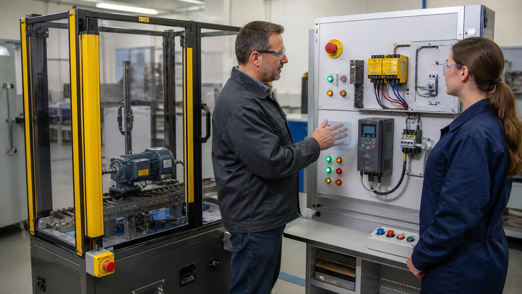
a guarded machinery training cell used to inspect emergency stopping, safety relays, light curtains, overload protection and drive safe-torque-off boundaries while studying safety PLC architecture, application boundaries and validation
The scene keeps safety PLC architecture, application boundaries and validation connected to a declared operating condition, observable evidence, safe boundaries and a result another person can reproduce.

System map / 02

Six concepts that control the result

Treat these as connected checkpoints. Each checkpoint has an expected state, an observable state and a boundary to the next part of the system. That structure prevents a software indication from being mistaken for physical proof.

NODE 01observable

Define the operating contract

hazard, safety function, required performance, safe state, demand rate, input subsystem, logic solver, output subsystem, diagnostics, reset, bypass, verification and validation. For safety PLC architecture, application boundaries and validation, record the initial condition, actor, requested change, observable result and stopping condition before selecting a tool or implementation.

NODE 02observable

Map the evidence path

hazardous event through protective device, safety input, certified logic, safety output, final element, energy or motion reduction and measured safe outcome. Separate request, internal state, output or service, physical or user-visible result and independent feedback so each boundary can be inspected.

NODE 03observable

Prove normal operation

one declared safety demand produces the specified safe state and restart remains inhibited until all defined conditions and deliberate action exist. Run more than one cycle from a known state and retain the values, timings or artifacts that demonstrate repeatability.

NODE 04observable

Exercise a boundary case

channel discrepancy, short circuit, stuck input, welded output device, communication loss, signature change, maintenance bypass, reset fault and power return. Choose minimum, maximum, simultaneous, delayed or restart conditions that reveal assumptions hidden by the happy path.

NODE 05observable

Diagnose a controlled fault

a hazard, requirement, architecture, input, logic, output, final-element, diagnostic, reset, calculation, software-lifecycle or validation mismatch. Preserve the first symptom, divide the system at a measurable boundary and change one condition only after predicting the result.

NODE 06observable

Transfer and hand over

the complete safety function assessed, implemented and validated on target equipment by competent people under applicable standards. Restore normal state, remove temporary changes, repeat affected checks and document which claims remain limited to the learning environment.

Procedure / 03

A six-step practice and commissioning workflow

Run the steps in order the first time. Later, the same structure becomes a diagnostic loop: define the expected condition, observe the boundary, interpret the difference and choose one proving action.

  1. 01

    Write the acceptance case

    Convert hazard, safety function, required performance, safe state, demand rate, input subsystem, logic solver, output subsystem, diagnostics, reset, bypass, verification and validation into initial conditions, one stimulus and observable pass criteria.

    Evidence: Another person can repeat the case without guessing the intended result.

    Avoid: Using page completion or an animation as the acceptance criterion.

  2. 02

    Build the map

    Document hazardous event through protective device, safety input, certified logic, safety output, final element, energy or motion reduction and measured safe outcome and name who owns each state or decision.

    Evidence: Every request and result has a source, destination and useful inspection point.

    Avoid: Using the same value as command, status and independent feedback.

  3. 03

    Run the baseline

    Apply one declared safety demand produces the specified safe state and restart remains inhibited until all defined conditions and deliberate action exist from a clean start and record the expected evidence.

    Evidence: Repeated runs produce the same bounded result.

    Avoid: Changing several parameters before a baseline exists.

  4. 04

    Challenge assumptions

    Test channel discrepancy, short circuit, stuck input, welded output device, communication loss, signature change, maintenance bypass, reset fault and power return without changing the acceptance contract.

    Evidence: Limits, timing and restart behavior reach defined states.

    Avoid: Testing only one ideal sequence.

  5. 05

    Isolate one failure

    Introduce or analyse a hazard, requirement, architecture, input, logic, output, final-element, diagnostic, reset, calculation, software-lifecycle or validation mismatch and locate the first disagreement.

    Evidence: The proving action distinguishes the leading hypotheses.

    Avoid: Resetting, forcing or replacing before evidence is retained.

  6. 06

    Close the evidence loop

    Complete the complete safety function assessed, implemented and validated on target equipment by competent people under applicable standards and repeat the affected regression cases.

    Evidence: Reference use is complete when inputs, assumptions, units or initial conditions are recorded and the result is independently checked at a useful boundary.

    Avoid: Treating an acknowledged message or one successful rerun as handover.

Diagnostic matrix / 04

Symptoms, proving points and next actions

The table is a reasoning aid, not a parts-replacement chart. Preserve the initial symptom, inspect the named boundary and use the interpretation to choose the next controlled test. Site safety procedures and equipment manuals remain authoritative.

Diagnostic symptoms, inspection points, interpretations and next actions for Safety PLCs for beginners: implementation, evidence and troubleshooting
Observed symptomInspectInterpretationNext proving action
The expected result is unclearRequirement, initial state, actor, stimulus, units and pass conditionThe technician, programmer and reviewer may be solving different versions of the task.Rewrite one observable acceptance case before continuing.
Internal state changes but the outcome does notRequest, final owner, output or service boundary and independent feedbackA software or interface indication proves intent at one layer, not the complete outcome.Trace the first boundary after the changing state.
Normal case passes but an edge case failsLimits, timing, simultaneous events, reset and restart assumptionsThe implementation contains a hidden assumption exposed by the changed condition.Add the failed boundary as a permanent regression case.
The failure disappears after resetOriginal symptom, histories, diagnostics, timestamps and active causeReset changed evidence or state without proving the initiating cause.Reproduce under a controlled condition and preserve pre/post-event data.
Simulator and target disagreeModel boundary, software version, task timing, I/O behavior, data types and configurationA learning model and the intended target do not share one of the recorded assumptions.Reduce the case and verify against current target documentation.
The result cannot be explainedPrediction, observation, proving action, alternative hypotheses and limitationsActivity occurred but the evidence is not yet transferable or reviewable.Have the learner defend the signal path and repeat a changed case.

Product evidence / 05

What the browser practice can actually demonstrate

The page connects definitions and worked examples to runnable tools, explicit assumptions and repeatable checks so a formula or pattern can be challenged.

Where simulation stops

The guide does not design, calculate or validate a safety system, certify code, select components or authorize modifications; qualified functional-safety work is required.

Commissioning notebook / 06

Six cases that turn the concepts into evidence

Use these as written briefs rather than click-through instructions. For every case, state the expected condition before acting, retain the first useful observation and explain why the final result proves the requirement. A different program or component choice can still be correct when it produces the same bounded behavior and evidence.

Case 01

predict → observe → prove

Prove define the operating contract

Engineering context. hazard, safety function, required performance, safe state, demand rate, input subsystem, logic solver, output subsystem, diagnostics, reset, bypass, verification and validation. For safety PLC architecture, application boundaries and validation, record the initial condition, actor, requested change, observable result and stopping condition before selecting a tool or implementation. Begin with a written normal condition and identify which request, state, physical result or communication value will provide independent confirmation. Do not begin by changing the configuration; the initial state is part of the evidence and should remain reproducible.

Controlled setup. Use the “Write the acceptance case” stage of the workflow: convert hazard, safety function, required performance, safe state, demand rate, input subsystem, logic solver, output subsystem, diagnostics, reset, bypass, verification and validation into initial conditions, one stimulus and observable pass criteria. The acceptance record should show this result: another person can repeat the case without guessing the intended result. Record initial conditions, the exact stimulus and the observation point so another learner can repeat the case without relying on your memory.

Fault challenge. Introduce or analyse “The expected result is unclear” as one bounded deviation. Inspect requirement, initial state, actor, stimulus, units and pass condition The working interpretation is that the technician, programmer and reviewer may be solving different versions of the task. The next proving action is to rewrite one observable acceptance case before continuing. Change only one condition before observing the result, and preserve timestamps or measurements where timing matters.

Review and recovery. The most common trap here is using page completion or an animation as the acceptance criterion. After restoring the cause, repeat the normal case and at least one stop, timeout, disconnect or restart boundary relevant to this topic. Remove temporary forces and bypasses, return the model to a known state and retain the evidence that both operation and recovery are deliberate.

Explain it aloud: What is a safety PLC? A defensible short answer is: It is a controller designed and certified for safety-related applications when used within its specified architecture, software lifecycle and application limits.

Case 02

predict → observe → prove

Prove map the evidence path

Engineering context. hazardous event through protective device, safety input, certified logic, safety output, final element, energy or motion reduction and measured safe outcome. Separate request, internal state, output or service, physical or user-visible result and independent feedback so each boundary can be inspected. Begin with a written normal condition and identify which request, state, physical result or communication value will provide independent confirmation. Do not begin by changing the configuration; the initial state is part of the evidence and should remain reproducible.

Controlled setup. Use the “Build the map” stage of the workflow: document hazardous event through protective device, safety input, certified logic, safety output, final element, energy or motion reduction and measured safe outcome and name who owns each state or decision. The acceptance record should show this result: every request and result has a source, destination and useful inspection point. Record initial conditions, the exact stimulus and the observation point so another learner can repeat the case without relying on your memory.

Fault challenge. Introduce or analyse “Internal state changes but the outcome does not” as one bounded deviation. Inspect request, final owner, output or service boundary and independent feedback The working interpretation is that a software or interface indication proves intent at one layer, not the complete outcome. The next proving action is to trace the first boundary after the changing state. Change only one condition before observing the result, and preserve timestamps or measurements where timing matters.

Review and recovery. The most common trap here is using the same value as command, status and independent feedback. After restoring the cause, repeat the normal case and at least one stop, timeout, disconnect or restart boundary relevant to this topic. Remove temporary forces and bypasses, return the model to a known state and retain the evidence that both operation and recovery are deliberate.

Explain it aloud: Is safety PLC programming just normal ladder logic? A defensible short answer is: No. Familiar notation may be used, but certified instructions, restricted workflows, signatures, diagnostics and formal verification and validation change the engineering process.

Case 03

predict → observe → prove

Prove prove normal operation

Engineering context. one declared safety demand produces the specified safe state and restart remains inhibited until all defined conditions and deliberate action exist. Run more than one cycle from a known state and retain the values, timings or artifacts that demonstrate repeatability. Begin with a written normal condition and identify which request, state, physical result or communication value will provide independent confirmation. Do not begin by changing the configuration; the initial state is part of the evidence and should remain reproducible.

Controlled setup. Use the “Run the baseline” stage of the workflow: apply one declared safety demand produces the specified safe state and restart remains inhibited until all defined conditions and deliberate action exist from a clean start and record the expected evidence. The acceptance record should show this result: repeated runs produce the same bounded result. Record initial conditions, the exact stimulus and the observation point so another learner can repeat the case without relying on your memory.

Fault challenge. Introduce or analyse “Normal case passes but an edge case fails” as one bounded deviation. Inspect limits, timing, simultaneous events, reset and restart assumptions The working interpretation is that the implementation contains a hidden assumption exposed by the changed condition. The next proving action is to add the failed boundary as a permanent regression case. Change only one condition before observing the result, and preserve timestamps or measurements where timing matters.

Review and recovery. The most common trap here is changing several parameters before a baseline exists. After restoring the cause, repeat the normal case and at least one stop, timeout, disconnect or restart boundary relevant to this topic. Remove temporary forces and bypasses, return the model to a known state and retain the evidence that both operation and recovery are deliberate.

Explain it aloud: What should I learn first about safety PLC architecture, application boundaries and validation? A defensible short answer is: Start with the operating contract and evidence path: hazard, safety function, required performance, safe state, demand rate, input subsystem, logic solver, output subsystem, diagnostics, reset, bypass, verification and validation, followed by hazardous event through protective device, safety input, certified logic, safety output, final element, energy or motion reduction and measured safe outcome. Add advanced features only after the baseline is predictable.

Case 04

predict → observe → prove

Prove exercise a boundary case

Engineering context. channel discrepancy, short circuit, stuck input, welded output device, communication loss, signature change, maintenance bypass, reset fault and power return. Choose minimum, maximum, simultaneous, delayed or restart conditions that reveal assumptions hidden by the happy path. Begin with a written normal condition and identify which request, state, physical result or communication value will provide independent confirmation. Do not begin by changing the configuration; the initial state is part of the evidence and should remain reproducible.

Controlled setup. Use the “Challenge assumptions” stage of the workflow: test channel discrepancy, short circuit, stuck input, welded output device, communication loss, signature change, maintenance bypass, reset fault and power return without changing the acceptance contract. The acceptance record should show this result: limits, timing and restart behavior reach defined states. Record initial conditions, the exact stimulus and the observation point so another learner can repeat the case without relying on your memory.

Fault challenge. Introduce or analyse “The failure disappears after reset” as one bounded deviation. Inspect original symptom, histories, diagnostics, timestamps and active cause The working interpretation is that reset changed evidence or state without proving the initiating cause. The next proving action is to reproduce under a controlled condition and preserve pre/post-event data. Change only one condition before observing the result, and preserve timestamps or measurements where timing matters.

Review and recovery. The most common trap here is testing only one ideal sequence. After restoring the cause, repeat the normal case and at least one stop, timeout, disconnect or restart boundary relevant to this topic. Remove temporary forces and bypasses, return the model to a known state and retain the evidence that both operation and recovery are deliberate.

Explain it aloud: How do I practise safety PLC architecture, application boundaries and validation effectively? A defensible short answer is: Use short cases with known initial conditions, a written prediction, one action and an observable result. Then alter a boundary or fault and explain why the evidence changed.

Case 05

predict → observe → prove

Prove diagnose a controlled fault

Engineering context. a hazard, requirement, architecture, input, logic, output, final-element, diagnostic, reset, calculation, software-lifecycle or validation mismatch. Preserve the first symptom, divide the system at a measurable boundary and change one condition only after predicting the result. Begin with a written normal condition and identify which request, state, physical result or communication value will provide independent confirmation. Do not begin by changing the configuration; the initial state is part of the evidence and should remain reproducible.

Controlled setup. Use the “Isolate one failure” stage of the workflow: introduce or analyse a hazard, requirement, architecture, input, logic, output, final-element, diagnostic, reset, calculation, software-lifecycle or validation mismatch and locate the first disagreement. The acceptance record should show this result: the proving action distinguishes the leading hypotheses. Record initial conditions, the exact stimulus and the observation point so another learner can repeat the case without relying on your memory.

Fault challenge. Introduce or analyse “Simulator and target disagree” as one bounded deviation. Inspect model boundary, software version, task timing, I/O behavior, data types and configuration The working interpretation is that a learning model and the intended target do not share one of the recorded assumptions. The next proving action is to reduce the case and verify against current target documentation. Change only one condition before observing the result, and preserve timestamps or measurements where timing matters.

Review and recovery. The most common trap here is resetting, forcing or replacing before evidence is retained. After restoring the cause, repeat the normal case and at least one stop, timeout, disconnect or restart boundary relevant to this topic. Remove temporary forces and bypasses, return the model to a known state and retain the evidence that both operation and recovery are deliberate.

Explain it aloud: What counts as proof of competence? A defensible short answer is: A repeatable artifact or system result plus an explanation of the signal path is stronger than time spent, screenshots or a copied answer. Physical competence requires separate supervised evidence.

Case 06

predict → observe → prove

Prove transfer and hand over

Engineering context. the complete safety function assessed, implemented and validated on target equipment by competent people under applicable standards. Restore normal state, remove temporary changes, repeat affected checks and document which claims remain limited to the learning environment. Begin with a written normal condition and identify which request, state, physical result or communication value will provide independent confirmation. Do not begin by changing the configuration; the initial state is part of the evidence and should remain reproducible.

Controlled setup. Use the “Close the evidence loop” stage of the workflow: complete the complete safety function assessed, implemented and validated on target equipment by competent people under applicable standards and repeat the affected regression cases. The acceptance record should show this result: reference use is complete when inputs, assumptions, units or initial conditions are recorded and the result is independently checked at a useful boundary. Record initial conditions, the exact stimulus and the observation point so another learner can repeat the case without relying on your memory.

Fault challenge. Introduce or analyse “The result cannot be explained” as one bounded deviation. Inspect prediction, observation, proving action, alternative hypotheses and limitations The working interpretation is that activity occurred but the evidence is not yet transferable or reviewable. The next proving action is to have the learner defend the signal path and repeat a changed case. Change only one condition before observing the result, and preserve timestamps or measurements where timing matters.

Review and recovery. The most common trap here is treating an acknowledged message or one successful rerun as handover. After restoring the cause, repeat the normal case and at least one stop, timeout, disconnect or restart boundary relevant to this topic. Remove temporary forces and bypasses, return the model to a known state and retain the evidence that both operation and recovery are deliberate.

Explain it aloud: Why test faults and restart behavior? A defensible short answer is: Because a hazard, requirement, architecture, input, logic, output, final-element, diagnostic, reset, calculation, software-lifecycle or validation mismatch or channel discrepancy, short circuit, stuck input, welded output device, communication loss, signature change, maintenance bypass, reset fault and power return can expose assumptions that never appear during ideal startup and steady operation.

Answer surface / 07

Questions people ask about Safety PLCs for beginners

These concise answers define the operating, training and product boundaries most often missed in broad summaries. The full workflow and diagnostic table above provide the evidence behind them.

What is a safety PLC?

It is a controller designed and certified for safety-related applications when used within its specified architecture, software lifecycle and application limits.

Is safety PLC programming just normal ladder logic?

No. Familiar notation may be used, but certified instructions, restricted workflows, signatures, diagnostics and formal verification and validation change the engineering process.

What should I learn first about safety PLC architecture, application boundaries and validation?

Start with the operating contract and evidence path: hazard, safety function, required performance, safe state, demand rate, input subsystem, logic solver, output subsystem, diagnostics, reset, bypass, verification and validation, followed by hazardous event through protective device, safety input, certified logic, safety output, final element, energy or motion reduction and measured safe outcome. Add advanced features only after the baseline is predictable.

How do I practise safety PLC architecture, application boundaries and validation effectively?

Use short cases with known initial conditions, a written prediction, one action and an observable result. Then alter a boundary or fault and explain why the evidence changed.

What counts as proof of competence?

A repeatable artifact or system result plus an explanation of the signal path is stronger than time spent, screenshots or a copied answer. Physical competence requires separate supervised evidence.

Why test faults and restart behavior?

Because a hazard, requirement, architecture, input, logic, output, final-element, diagnostic, reset, calculation, software-lifecycle or validation mismatch or channel discrepancy, short circuit, stuck input, welded output device, communication loss, signature change, maintenance bypass, reset fault and power return can expose assumptions that never appear during ideal startup and steady operation.

Can browser practice replace official software or hardware?

No. It can build concepts and diagnostic reasoning. Exact firmware, I/O electrical behavior, networking, safety and commissioning require current official tools, documentation and target equipment.

How should progress be documented?

Keep the requirement, initial state, program or configuration, observed values, fault hypothesis, proving action, recovery result and a concise limitations statement.