PLC Simulator
PLC field notesscada

SCADA vs PLC: What Each Does, Where One Ends and the Other Begins

SCADA vs PLC explained clearly: what each layer does, who runs the logic, who runs the display, why a PLC keeps running when SCADA goes offline, and which one you need to learn first.

PLC Simulation Software9 min read

TL;DR: A PLC (Programmable Logic Controller) executes control logic in real time and drives physical outputs — motors, valves, actuators. SCADA (Supervisory Control and Data Acquisition) is a software layer that reads data from many PLCs across a site, displays it to operators, logs it historically, and manages alarms. The PLC controls the machine. SCADA watches the plant. A plant has one SCADA system and dozens or hundreds of PLCs.
SCADA vs PLC — where control logic lives vs where supervision lives

These two terms are often thrown together as if they are the same thing. They are not. Every industrial site has PLCs. Most medium-to-large sites also have SCADA. But the jobs they do are completely different, and mixing them up leads to misunderstandings about how automation actually works.

What a PLC Does

A PLC executes a control program — typically ladder logic — on a continuous scan cycle of 5 to 50 milliseconds. Every scan it reads its physical inputs (sensors, pushbuttons, limit switches), runs the program logic, and updates its physical outputs (motor contactors, solenoid valves, indicator lamps). This loop runs autonomously. The PLC does not need a human watching, an HMI connected, or a SCADA server reachable. If the control logic says start the pump, the pump starts.

Key characteristics of a PLC:

  • Deterministic: the same input conditions produce the same output in the same scan, every time.
  • Safety-critical: the PLC enforces interlocks and e-stop logic. If the e-stop is pressed, the output goes off in the current scan because the logic says so — regardless of what SCADA thinks.
  • Directly wired: sensors and actuators are hard-wired to I/O cards on the PLC chassis.
  • Scope: one machine or process unit. A pump skid has one PLC. A conveyor section has one PLC.

What SCADA Does

SCADA is a software application running on a server (or set of servers) that collects data from many PLCs across a site, displays it on operator workstations, logs it to a historian database, and manages alarms. SCADA does not control anything directly — it reads PLC data, displays it, and allows supervisory operators to send setpoints and commands back to PLCs.

Key characteristics of SCADA:

  • Supervisory: it watches and reports. It does not run real-time safety logic.
  • Multi-node: it connects to dozens or hundreds of PLCs, RTUs, and field devices.
  • Historical: SCADA historian databases store process values at configured intervals for trending, reporting, and compliance.
  • Alarming: SCADA aggregates alarms from all connected PLCs into one operator view with acknowledgement tracking.
  • If the SCADA server goes offline, every PLC it was watching keeps running. The machines do not stop.

Common SCADA platforms: Ignition (Inductive Automation), WinCC SCADA (Siemens), iFIX (GE), FactoryTalk View Site Edition (Rockwell).

Side-by-Side Comparison
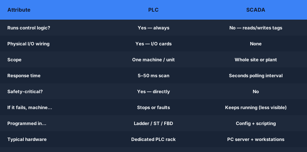
SCADA vs PLC — roles, scope, real-time, and failure consequence compared

Reference tableSwipe
PLCSCADA
Primary roleExecute control logicSupervise, log, alarm
Runs the logic?Yes — alwaysNo — reads/writes tags
Physical output wiringYes — I/O cardsNone
ScopeOne machine / unitWhole site or multiple sites
Real-time response5–50 ms scanSeconds polling interval
Safety-critical?Yes — directlyNo
Runs without operatorYesYes — data logs unattended
If it fails, machine…Stops or faultsKeeps running (less visible)
Programmed in…Ladder, ST, FBD, IL, SFCConfiguration + scripting
Typical hardwareDedicated PLC rackPC server + workstations

Where They Connect

SCADA reads PLC data using an industrial communication protocol — EtherNet/IP for Allen-Bradley, PROFINET for Siemens, Modbus TCP for most other devices, or OPC UA as a vendor-neutral standard. The SCADA server has a driver that polls each PLC for tag values at a configured rate (often 1–5 seconds for display, faster for alarm detection).
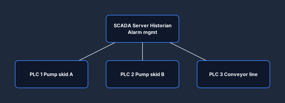
SCADA polling many PLCs — the supervisory network architecture

The SCADA system maintains a tag database that mirrors the PLC tag database. An operator looking at the pump station screen on a SCADA workstation is seeing data that was polled from the pump skid PLC moments ago — not a live hardwired connection.

When an operator at the SCADA workstation changes a setpoint (say, adjusting a flow controller), SCADA writes the new value to the corresponding PLC tag. The PLC logic reads that tag and acts on it in the next scan. SCADA is always communicating through the PLC, never bypassing it.

Which One Do You Need First?

If you are starting a career in controls or automation: learn PLC programming first. The PLC is where the actual control logic lives. Every automation role — controls technician, automation engineer, commissioning technician — requires PLC skills. SCADA is the second layer you add after you understand what you are supervising.

If you already know PLCs and need to expand: SCADA adds historian, alarming, and multi-site supervision to your skill set. Ignition Maker Edition is free and a sensible starting point.

If a job posting lists both: they want someone who can wire up a PLC, write and troubleshoot ladder logic, AND configure SCADA tags and screens. Those are different skills but both are learnable.

Real Plant Examples

Water treatment plant: Dozens of pump stations across a catchment, each with its own Allen-Bradley CompactLogix PLC controlling the pumps locally. One Ignition SCADA server at the operations centre reads flow, level, and fault status from every station, logs the data to historian, and alerts the on-call technician if a pump faults. The pumps keep running when SCADA is offline — the local PLC logic handles start/stop based on level switches regardless.

Automotive assembly line: Each robot cell and conveyor section has a Siemens S7-1500 PLC. A FactoryTalk View SE SCADA system provides the shift supervisor with a plant-wide production dashboard, downtime tracking, and OEE reporting. The robot cells do not consult SCADA before each weld.

Oil and gas pipeline: RTUs (Remote Terminal Units) — essentially field-hardened PLCs — monitor pressure, temperature, and valve state at each station along hundreds of kilometres of pipeline. SCADA at the central control room provides the operator with a complete pipeline view, trending, and alarm management. The RTUs act autonomously on local logic if SCADA communication is lost.

Common Confusions Cleared Up

"SCADA controls the machines." SCADA supervises them. Control logic lives in the PLC. SCADA can send setpoints and commands to the PLC, but the PLC validates them against its logic before acting. If a safety interlock in the PLC prevents an action, a SCADA command cannot override it.

"You need SCADA before you can monitor a machine." Not at all. An HMI panel connected directly to the PLC provides machine-level monitoring without any SCADA server involved. SCADA becomes relevant when you need to aggregate many machines, log historical data, or monitor remotely.

"SCADA and HMI are the same thing." An HMI is typically a dedicated panel or screen for one machine, reading one PLC. SCADA is a server-based system connecting many PLCs and many operator workstations across a site. The boundary is blurring as software like Ignition can serve both roles, but conceptually they are different layers. See the PLC vs HMI post for the full breakdown of that layer.

Frequently Asked Questions

Q: Can SCADA work without a PLC?

A: SCADA can connect to any device that speaks an industrial protocol — RTUs, smart meters, DCS controllers — not only PLCs. But in most industrial automation, the PLC is the field device SCADA talks to. The two are not interchangeable; they occupy different layers.

Q: What is the difference between SCADA and DCS?

A: A DCS (Distributed Control System) is an integrated platform where both the control logic and the supervisory layer come from the same vendor (Emerson DeltaV, Honeywell Experion, ABB 800xA). SCADA is typically a supervisory software layer bolted on top of separate PLCs/RTUs from any vendor. DCS is more common in continuous process industries (chemicals, oil refining, power generation); SCADA + PLC is more common in discrete manufacturing and utilities.

Q: Does SCADA replace the PLC?

A: No. SCADA can write commands to PLCs, but it does not replace the real-time, safety-critical local control function. Removing the PLC would mean SCADA would need to respond to field signals and drive outputs directly — at network latency, with no deterministic scan. That is not safe for machine control. The PLC layer is always there.

Q: Which pays more, PLC or SCADA skills?

A: Both together pay more than either alone. PLC programming is the foundational skill with higher demand for entry-level roles. SCADA skills add salary leverage, especially in utilities (water, power, gas) and process industries where SCADA configuration and historian management are billable project work.


Ready to practise the PLC side of the equation? The motor start-stop scenario is free, runs in your browser, and auto-grades your ladder logic. No install, no hardware.
Start practising PLC logic free →

ShareX / TwitterLinkedIn

From reading to running logic

Practice this yourself in the simulator

Start with guided PLC practice in your browser. No install and no credit card required.

Start practising free

Continue learning

Related field notes

All articles
scada
hmi

SCADA vs HMI: Same Screen, Very Different Jobs

SCADA vs HMI: an HMI is a panel for one machine; SCADA is a server supervising dozens of PLCs. This post covers architecture, historian, alarms, scope, and which one a controls engineer actually needs.

8 min read
sensors
temperature

Thermocouple vs RTD vs Thermistor: Which Temperature Sensor for Your PLC?

Thermocouples cover wide temperature ranges with simple wiring. RTDs (PT100) are more accurate and stable. Thermistors are accurate over a narrow range at low cost. Learn the trade-offs, wiring, and PLC module requirements for each.

10 min read
scada
dcs

SCADA vs DCS: How to Tell Them Apart and When Each Is Used

SCADA vs DCS compared: integrated platform vs open supervision layer, continuous process vs discrete manufacturing, response time, vendor lock-in, and the convergence happening right now.

9 min read

Software evaluation field guide

SCADA versus PLC: implementation, evidence and troubleshooting

Direct answer

SCADA versus PLC becomes useful when it connects control-loop timing, deterministic logic, local autonomy, i/o ownership, supervisory scope, users and roles, visualization, commands, alarms, trends, historian, redundancy, cybersecurity and lifecycle with field condition through plc i/o and logic to actuator and feedback while selected tags travel through communications and quality into scada display, alarm, command and history, then proves loss of the supervisory layer leaves the declared essential local control behavior in a defined state while data and commands recover correctly under normal, boundary, fault and recovery conditions. The objective is a repeatable engineering or learning result, not merely activity inside a page or tool.

This guide is written for automation beginners, technical buyers and operators distinguishing real-time controller decisions from supervisory visualization, commands, alarms, trends and records. The intended result is specific: the reader can assign each requirement to a controller, SCADA layer or shared interface and trace data and commands without confusing display state with physical feedback.

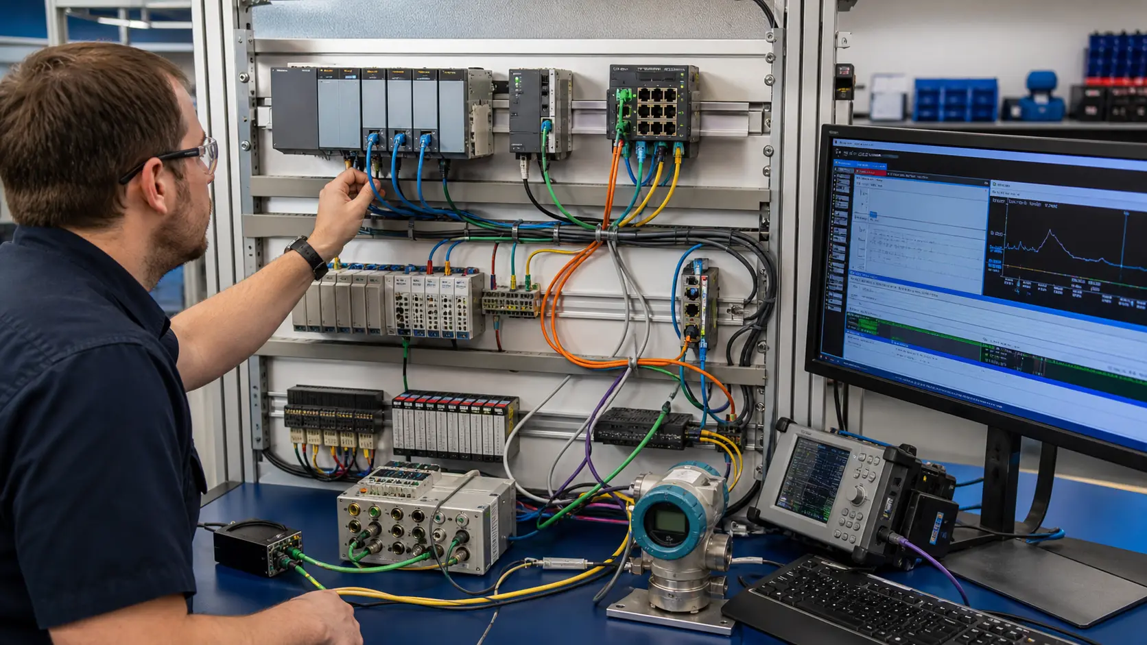
an industrial network diagnostics lab connecting generic controllers, distributed I/O, serial and Ethernet paths to protocol traces and process values while studying SCADA and PLC roles, boundaries and system evidence
The scene keeps SCADA and PLC roles, boundaries and system evidence connected to a declared operating condition, observable evidence, safe boundaries and a result another person can reproduce.

System map / 02

Six concepts that control the result

Treat these as connected checkpoints. Each checkpoint has an expected state, an observable state and a boundary to the next part of the system. That structure prevents a software indication from being mistaken for physical proof.

NODE 01observable

Define the operating contract

control-loop timing, deterministic logic, local autonomy, I/O ownership, supervisory scope, users and roles, visualization, commands, alarms, trends, historian, redundancy, cybersecurity and lifecycle. For SCADA and PLC roles, boundaries and system evidence, record the initial condition, actor, requested change, observable result and stopping condition before selecting a tool or implementation.

NODE 02observable

Map the evidence path

field condition through PLC I/O and logic to actuator and feedback while selected tags travel through communications and quality into SCADA display, alarm, command and history. Separate request, internal state, output or service, physical or user-visible result and independent feedback so each boundary can be inspected.

NODE 03observable

Prove normal operation

loss of the supervisory layer leaves the declared essential local control behavior in a defined state while data and commands recover correctly. Run more than one cycle from a known state and retain the values, timings or artifacts that demonstrate repeatability.

NODE 04observable

Exercise a boundary case

bad quality, stale timestamp, communication loss, server restart, PLC restart, unauthorized command, alarm flood, mapping error and failover. Choose minimum, maximum, simultaneous, delayed or restart conditions that reveal assumptions hidden by the happy path.

NODE 05observable

Diagnose a controlled fault

a field, PLC, communications, quality, SCADA, user-role, command, alarm, historian, availability or security mismatch. Preserve the first symptom, divide the system at a measurable boundary and change one condition only after predicting the result.

NODE 06observable

Transfer and hand over

the architecture tested under target timing, failure, access-control and recovery conditions with approved cybersecurity and operating procedures. Restore normal state, remove temporary changes, repeat affected checks and document which claims remain limited to the learning environment.

Procedure / 03

A six-step practice and commissioning workflow

Run the steps in order the first time. Later, the same structure becomes a diagnostic loop: define the expected condition, observe the boundary, interpret the difference and choose one proving action.

  1. 01

    Write the acceptance case

    Convert control-loop timing, deterministic logic, local autonomy, i/o ownership, supervisory scope, users and roles, visualization, commands, alarms, trends, historian, redundancy, cybersecurity and lifecycle into initial conditions, one stimulus and observable pass criteria.

    Evidence: Another person can repeat the case without guessing the intended result.

    Avoid: Using page completion or an animation as the acceptance criterion.

  2. 02

    Build the map

    Document field condition through plc i/o and logic to actuator and feedback while selected tags travel through communications and quality into scada display, alarm, command and history and name who owns each state or decision.

    Evidence: Every request and result has a source, destination and useful inspection point.

    Avoid: Using the same value as command, status and independent feedback.

  3. 03

    Run the baseline

    Apply loss of the supervisory layer leaves the declared essential local control behavior in a defined state while data and commands recover correctly from a clean start and record the expected evidence.

    Evidence: Repeated runs produce the same bounded result.

    Avoid: Changing several parameters before a baseline exists.

  4. 04

    Challenge assumptions

    Test bad quality, stale timestamp, communication loss, server restart, plc restart, unauthorized command, alarm flood, mapping error and failover without changing the acceptance contract.

    Evidence: Limits, timing and restart behavior reach defined states.

    Avoid: Testing only one ideal sequence.

  5. 05

    Isolate one failure

    Introduce or analyse a field, plc, communications, quality, scada, user-role, command, alarm, historian, availability or security mismatch and locate the first disagreement.

    Evidence: The proving action distinguishes the leading hypotheses.

    Avoid: Resetting, forcing or replacing before evidence is retained.

  6. 06

    Close the evidence loop

    Complete the architecture tested under target timing, failure, access-control and recovery conditions with approved cybersecurity and operating procedures and repeat the affected regression cases.

    Evidence: An evaluation is complete when the same representative job is tested in each candidate and differences are recorded as evidence rather than inferred from feature labels.

    Avoid: Treating an acknowledged message or one successful rerun as handover.

Diagnostic matrix / 04

Symptoms, proving points and next actions

The table is a reasoning aid, not a parts-replacement chart. Preserve the initial symptom, inspect the named boundary and use the interpretation to choose the next controlled test. Site safety procedures and equipment manuals remain authoritative.

Diagnostic symptoms, inspection points, interpretations and next actions for SCADA versus PLC: implementation, evidence and troubleshooting
Observed symptomInspectInterpretationNext proving action
The expected result is unclearRequirement, initial state, actor, stimulus, units and pass conditionThe evaluator, instructor and technical buyer may be solving different versions of the task.Rewrite one observable acceptance case before continuing.
Internal state changes but the outcome does notRequest, final owner, output or service boundary and independent feedbackA software or interface indication proves intent at one layer, not the complete outcome.Trace the first boundary after the changing state.
Normal case passes but an edge case failsLimits, timing, simultaneous events, reset and restart assumptionsThe implementation contains a hidden assumption exposed by the changed condition.Add the failed boundary as a permanent regression case.
The failure disappears after resetOriginal symptom, histories, diagnostics, timestamps and active causeReset changed evidence or state without proving the initiating cause.Reproduce under a controlled condition and preserve pre/post-event data.
Simulator and target disagreeModel boundary, software version, task timing, I/O behavior, data types and configurationA learning model and the intended target do not share one of the recorded assumptions.Reduce the case and verify against current target documentation.
The result cannot be explainedPrediction, observation, proving action, alternative hypotheses and limitationsActivity occurred but the evidence is not yet transferable or reviewable.Have the learner defend the signal path and repeat a changed case.

Product evidence / 05

What the browser practice can actually demonstrate

The public product surface exposes runnable examples, capability boundaries, pricing context and test-harness behavior that can be checked before a purchasing decision.

Where simulation stops

A high-level comparison cannot choose architecture, validate timing, cybersecurity, availability, alarm management or safety and does not cover every product topology.

Commissioning notebook / 06

Six cases that turn the concepts into evidence

Use these as written briefs rather than click-through instructions. For every case, state the expected condition before acting, retain the first useful observation and explain why the final result proves the requirement. A different program or component choice can still be correct when it produces the same bounded behavior and evidence.

Case 01

predict → observe → prove

Prove define the operating contract

Engineering context. control-loop timing, deterministic logic, local autonomy, I/O ownership, supervisory scope, users and roles, visualization, commands, alarms, trends, historian, redundancy, cybersecurity and lifecycle. For SCADA and PLC roles, boundaries and system evidence, record the initial condition, actor, requested change, observable result and stopping condition before selecting a tool or implementation. Begin with a written normal condition and identify which request, state, physical result or communication value will provide independent confirmation. Do not begin by changing the configuration; the initial state is part of the evidence and should remain reproducible.

Controlled setup. Use the “Write the acceptance case” stage of the workflow: convert control-loop timing, deterministic logic, local autonomy, i/o ownership, supervisory scope, users and roles, visualization, commands, alarms, trends, historian, redundancy, cybersecurity and lifecycle into initial conditions, one stimulus and observable pass criteria. The acceptance record should show this result: another person can repeat the case without guessing the intended result. Record initial conditions, the exact stimulus and the observation point so another learner can repeat the case without relying on your memory.

Fault challenge. Introduce or analyse “The expected result is unclear” as one bounded deviation. Inspect requirement, initial state, actor, stimulus, units and pass condition The working interpretation is that the evaluator, instructor and technical buyer may be solving different versions of the task. The next proving action is to rewrite one observable acceptance case before continuing. Change only one condition before observing the result, and preserve timestamps or measurements where timing matters.

Review and recovery. The most common trap here is using page completion or an animation as the acceptance criterion. After restoring the cause, repeat the normal case and at least one stop, timeout, disconnect or restart boundary relevant to this topic. Remove temporary forces and bypasses, return the model to a known state and retain the evidence that both operation and recovery are deliberate.

Explain it aloud: What is the difference between a PLC and SCADA? A defensible short answer is: A PLC performs local control and I/O logic; SCADA supervises wider systems through visualization, commands, alarms, trends and records, with boundaries varying by architecture.

Case 02

predict → observe → prove

Prove map the evidence path

Engineering context. field condition through PLC I/O and logic to actuator and feedback while selected tags travel through communications and quality into SCADA display, alarm, command and history. Separate request, internal state, output or service, physical or user-visible result and independent feedback so each boundary can be inspected. Begin with a written normal condition and identify which request, state, physical result or communication value will provide independent confirmation. Do not begin by changing the configuration; the initial state is part of the evidence and should remain reproducible.

Controlled setup. Use the “Build the map” stage of the workflow: document field condition through plc i/o and logic to actuator and feedback while selected tags travel through communications and quality into scada display, alarm, command and history and name who owns each state or decision. The acceptance record should show this result: every request and result has a source, destination and useful inspection point. Record initial conditions, the exact stimulus and the observation point so another learner can repeat the case without relying on your memory.

Fault challenge. Introduce or analyse “Internal state changes but the outcome does not” as one bounded deviation. Inspect request, final owner, output or service boundary and independent feedback The working interpretation is that a software or interface indication proves intent at one layer, not the complete outcome. The next proving action is to trace the first boundary after the changing state. Change only one condition before observing the result, and preserve timestamps or measurements where timing matters.

Review and recovery. The most common trap here is using the same value as command, status and independent feedback. After restoring the cause, repeat the normal case and at least one stop, timeout, disconnect or restart boundary relevant to this topic. Remove temporary forces and bypasses, return the model to a known state and retain the evidence that both operation and recovery are deliberate.

Explain it aloud: Can SCADA run without a PLC? A defensible short answer is: Some systems connect to other controllers or devices, but equipment still needs an appropriate control layer; a SCADA screen is not inherently a deterministic machine controller.

Case 03

predict → observe → prove

Prove prove normal operation

Engineering context. loss of the supervisory layer leaves the declared essential local control behavior in a defined state while data and commands recover correctly. Run more than one cycle from a known state and retain the values, timings or artifacts that demonstrate repeatability. Begin with a written normal condition and identify which request, state, physical result or communication value will provide independent confirmation. Do not begin by changing the configuration; the initial state is part of the evidence and should remain reproducible.

Controlled setup. Use the “Run the baseline” stage of the workflow: apply loss of the supervisory layer leaves the declared essential local control behavior in a defined state while data and commands recover correctly from a clean start and record the expected evidence. The acceptance record should show this result: repeated runs produce the same bounded result. Record initial conditions, the exact stimulus and the observation point so another learner can repeat the case without relying on your memory.

Fault challenge. Introduce or analyse “Normal case passes but an edge case fails” as one bounded deviation. Inspect limits, timing, simultaneous events, reset and restart assumptions The working interpretation is that the implementation contains a hidden assumption exposed by the changed condition. The next proving action is to add the failed boundary as a permanent regression case. Change only one condition before observing the result, and preserve timestamps or measurements where timing matters.

Review and recovery. The most common trap here is changing several parameters before a baseline exists. After restoring the cause, repeat the normal case and at least one stop, timeout, disconnect or restart boundary relevant to this topic. Remove temporary forces and bypasses, return the model to a known state and retain the evidence that both operation and recovery are deliberate.

Explain it aloud: What should I learn first about SCADA and PLC roles, boundaries and system evidence? A defensible short answer is: Start with the operating contract and evidence path: control-loop timing, deterministic logic, local autonomy, i/o ownership, supervisory scope, users and roles, visualization, commands, alarms, trends, historian, redundancy, cybersecurity and lifecycle, followed by field condition through plc i/o and logic to actuator and feedback while selected tags travel through communications and quality into scada display, alarm, command and history. Add advanced features only after the baseline is predictable.

Case 04

predict → observe → prove

Prove exercise a boundary case

Engineering context. bad quality, stale timestamp, communication loss, server restart, PLC restart, unauthorized command, alarm flood, mapping error and failover. Choose minimum, maximum, simultaneous, delayed or restart conditions that reveal assumptions hidden by the happy path. Begin with a written normal condition and identify which request, state, physical result or communication value will provide independent confirmation. Do not begin by changing the configuration; the initial state is part of the evidence and should remain reproducible.

Controlled setup. Use the “Challenge assumptions” stage of the workflow: test bad quality, stale timestamp, communication loss, server restart, plc restart, unauthorized command, alarm flood, mapping error and failover without changing the acceptance contract. The acceptance record should show this result: limits, timing and restart behavior reach defined states. Record initial conditions, the exact stimulus and the observation point so another learner can repeat the case without relying on your memory.

Fault challenge. Introduce or analyse “The failure disappears after reset” as one bounded deviation. Inspect original symptom, histories, diagnostics, timestamps and active cause The working interpretation is that reset changed evidence or state without proving the initiating cause. The next proving action is to reproduce under a controlled condition and preserve pre/post-event data. Change only one condition before observing the result, and preserve timestamps or measurements where timing matters.

Review and recovery. The most common trap here is testing only one ideal sequence. After restoring the cause, repeat the normal case and at least one stop, timeout, disconnect or restart boundary relevant to this topic. Remove temporary forces and bypasses, return the model to a known state and retain the evidence that both operation and recovery are deliberate.

Explain it aloud: How do I practise SCADA and PLC roles, boundaries and system evidence effectively? A defensible short answer is: Use short cases with known initial conditions, a written prediction, one action and an observable result. Then alter a boundary or fault and explain why the evidence changed.

Case 05

predict → observe → prove

Prove diagnose a controlled fault

Engineering context. a field, PLC, communications, quality, SCADA, user-role, command, alarm, historian, availability or security mismatch. Preserve the first symptom, divide the system at a measurable boundary and change one condition only after predicting the result. Begin with a written normal condition and identify which request, state, physical result or communication value will provide independent confirmation. Do not begin by changing the configuration; the initial state is part of the evidence and should remain reproducible.

Controlled setup. Use the “Isolate one failure” stage of the workflow: introduce or analyse a field, plc, communications, quality, scada, user-role, command, alarm, historian, availability or security mismatch and locate the first disagreement. The acceptance record should show this result: the proving action distinguishes the leading hypotheses. Record initial conditions, the exact stimulus and the observation point so another learner can repeat the case without relying on your memory.

Fault challenge. Introduce or analyse “Simulator and target disagree” as one bounded deviation. Inspect model boundary, software version, task timing, I/O behavior, data types and configuration The working interpretation is that a learning model and the intended target do not share one of the recorded assumptions. The next proving action is to reduce the case and verify against current target documentation. Change only one condition before observing the result, and preserve timestamps or measurements where timing matters.

Review and recovery. The most common trap here is resetting, forcing or replacing before evidence is retained. After restoring the cause, repeat the normal case and at least one stop, timeout, disconnect or restart boundary relevant to this topic. Remove temporary forces and bypasses, return the model to a known state and retain the evidence that both operation and recovery are deliberate.

Explain it aloud: What counts as proof of competence? A defensible short answer is: A repeatable artifact or system result plus an explanation of the signal path is stronger than time spent, screenshots or a copied answer. Physical competence requires separate supervised evidence.

Case 06

predict → observe → prove

Prove transfer and hand over

Engineering context. the architecture tested under target timing, failure, access-control and recovery conditions with approved cybersecurity and operating procedures. Restore normal state, remove temporary changes, repeat affected checks and document which claims remain limited to the learning environment. Begin with a written normal condition and identify which request, state, physical result or communication value will provide independent confirmation. Do not begin by changing the configuration; the initial state is part of the evidence and should remain reproducible.

Controlled setup. Use the “Close the evidence loop” stage of the workflow: complete the architecture tested under target timing, failure, access-control and recovery conditions with approved cybersecurity and operating procedures and repeat the affected regression cases. The acceptance record should show this result: an evaluation is complete when the same representative job is tested in each candidate and differences are recorded as evidence rather than inferred from feature labels. Record initial conditions, the exact stimulus and the observation point so another learner can repeat the case without relying on your memory.

Fault challenge. Introduce or analyse “The result cannot be explained” as one bounded deviation. Inspect prediction, observation, proving action, alternative hypotheses and limitations The working interpretation is that activity occurred but the evidence is not yet transferable or reviewable. The next proving action is to have the learner defend the signal path and repeat a changed case. Change only one condition before observing the result, and preserve timestamps or measurements where timing matters.

Review and recovery. The most common trap here is treating an acknowledged message or one successful rerun as handover. After restoring the cause, repeat the normal case and at least one stop, timeout, disconnect or restart boundary relevant to this topic. Remove temporary forces and bypasses, return the model to a known state and retain the evidence that both operation and recovery are deliberate.

Explain it aloud: Why test faults and restart behavior? A defensible short answer is: Because a field, plc, communications, quality, scada, user-role, command, alarm, historian, availability or security mismatch or bad quality, stale timestamp, communication loss, server restart, plc restart, unauthorized command, alarm flood, mapping error and failover can expose assumptions that never appear during ideal startup and steady operation.

Answer surface / 07

Questions people ask about SCADA versus PLC

These concise answers define the operating, training and product boundaries most often missed in broad summaries. The full workflow and diagnostic table above provide the evidence behind them.

What is the difference between a PLC and SCADA?

A PLC performs local control and I/O logic; SCADA supervises wider systems through visualization, commands, alarms, trends and records, with boundaries varying by architecture.

Can SCADA run without a PLC?

Some systems connect to other controllers or devices, but equipment still needs an appropriate control layer; a SCADA screen is not inherently a deterministic machine controller.

What should I learn first about SCADA and PLC roles, boundaries and system evidence?

Start with the operating contract and evidence path: control-loop timing, deterministic logic, local autonomy, i/o ownership, supervisory scope, users and roles, visualization, commands, alarms, trends, historian, redundancy, cybersecurity and lifecycle, followed by field condition through plc i/o and logic to actuator and feedback while selected tags travel through communications and quality into scada display, alarm, command and history. Add advanced features only after the baseline is predictable.

How do I practise SCADA and PLC roles, boundaries and system evidence effectively?

Use short cases with known initial conditions, a written prediction, one action and an observable result. Then alter a boundary or fault and explain why the evidence changed.

What counts as proof of competence?

A repeatable artifact or system result plus an explanation of the signal path is stronger than time spent, screenshots or a copied answer. Physical competence requires separate supervised evidence.

Why test faults and restart behavior?

Because a field, plc, communications, quality, scada, user-role, command, alarm, historian, availability or security mismatch or bad quality, stale timestamp, communication loss, server restart, plc restart, unauthorized command, alarm flood, mapping error and failover can expose assumptions that never appear during ideal startup and steady operation.

Can browser practice replace official software or hardware?

No. It can build concepts and diagnostic reasoning. Exact firmware, I/O electrical behavior, networking, safety and commissioning require current official tools, documentation and target equipment.

How should progress be documented?

Keep the requirement, initial state, program or configuration, observed values, fault hypothesis, proving action, recovery result and a concise limitations statement.