PLC Simulator
PLC field noteselectrical

Motor Starter vs VFD: When Direct-On-Line Is Enough and When It Is Not

Motor starter vs VFD compared: DOL starting vs variable speed, energy savings, starting current, soft start, mechanical wear, and when the extra cost of a VFD is justified.

PLC Simulation Software9 min read

TL;DR: A motor starter (DOL) connects a motor directly to the mains supply — the motor goes from zero to full speed in one step, drawing 6–8× full-load current at start. A VFD (Variable Frequency Drive) controls the motor by varying the voltage and frequency supplied to it, enabling controlled acceleration, variable speed during run, and energy savings on loads where speed matters. Use DOL when speed is fixed and starting inrush is acceptable. Use a VFD when you need variable speed, controlled ramp, or significant energy savings on fans and pumps.
Motor starter vs VFD — direct-on-line vs variable frequency control

Every AC induction motor application is a choice between these two approaches. Most motors in a facility run at one: on or off, fixed speed. A smaller number need variable speed, soft ramp, or energy optimisation. Knowing which application demands which solution prevents over-engineering and under-specifying.

What a Direct-On-Line Motor Starter Does

A DOL (Direct-On-Line) motor starter — a contactor plus an overload relay — applies full mains voltage directly to the motor terminals. The motor accelerates from rest to full synchronous speed (minus slip) in a fraction of a second for small motors, and a few seconds for larger ones. Simple, robust, cheap.

The downside of DOL starting is inrush current: a three-phase induction motor draws 6–8 times its full-load current during the first acceleration phase. On a 7.5 kW motor (FLC ~15A), that is 90–120A for 1–3 seconds. In facilities with weak supplies, transformer-limited sites, or many motors starting simultaneously, this inrush causes voltage sag that affects other equipment.

DOL starters have no ability to control speed during run. The motor runs at its rated synchronous speed minus slip, full stop. For a 4-pole motor on 50 Hz supply, that is approximately 1480 RPM.

For full details on the motor starter circuit — contactor, overload relay, control circuit, and PLC interlocking — see the motor starter vs contactor post.

What a VFD Does

A VFD (Variable Frequency Drive, also called an inverter or adjustable-speed drive) converts the fixed mains frequency and voltage to a variable frequency and voltage. The motor sees whatever frequency the drive outputs — 5 Hz, 30 Hz, 50 Hz, 60 Hz, 80 Hz — and runs at proportional speed. The basic relationship is:

Motor speed (RPM) = (120 × output frequency) / number of poles

A 4-pole motor at 50 Hz input runs at ~1480 RPM. At 25 Hz, it runs at ~740 RPM. At 60 Hz (on a 50 Hz supply), it runs at ~1780 RPM (with appropriate motor/VFD rating for field weakening above base speed).

The VFD also controls the V/Hz ratio (or uses vector control) to maintain rated flux at all speeds, protecting the motor.

Key things a VFD does that a DOL starter cannot:

  • Variable speed: the fundamental capability. Fans, pumps, compressors, conveyors with variable throughput.
  • Controlled acceleration: the VFD ramps frequency up over a set acceleration time (1 second to several minutes). The motor current during acceleration is limited to the drive's current limit setpoint — typically 150% FLC, far below DOL inrush.
  • Controlled deceleration: ramped stop, not coast. Important for conveyors, centrifuges, and applications where abrupt stops cause mechanical or process problems.
  • Built-in overload protection: the drive monitors motor current and trips on overload. The separate overload relay in a DOL starter is not needed.
  • Energy savings: on centrifugal fans and pumps, reducing speed by 20% reduces power consumption by ~50% (cube law). A pump or fan that previously ran at full speed and was throttled by a valve or damper can instead be slowed by the VFD with dramatic energy savings.

Side-by-Side Comparison
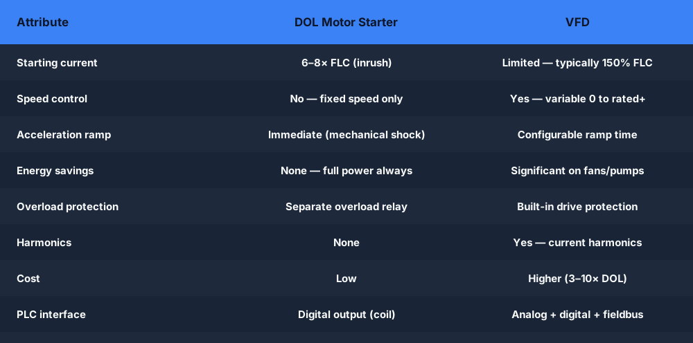
Motor starter vs VFD — starting current, speed control, energy, cost, and protection compared

Reference tableSwipe
DOL Motor StarterVFD
Starting current6–8× FLC (inrush)Limited (typically 150% FLC)
Speed controlNo — fixed speed onlyYes — variable 0 to rated+
Acceleration rampImmediate (mechanical shock)Configurable (0.1 s to minutes)
DecelerationCoast or mechanical brakeRamp or DC inject braking
Energy savings (fans/pumps)None — motor runs at full powerSignificant — cube law on centrifugal loads
Overload protectionSeparate overload relay requiredBuilt-in, often with logging
Harmonics (power quality)NoneYes — current harmonic injection into supply
Motor compatibilityAny standard AC motorStandard AC motor; VFD-rated for long cables
CostLowHigher — 3–10× a DOL starter for same rating
MaintenanceAlmost noneDrive cooling fans, capacitor life
PLC interfaceDigital outputs (coil)Analog + digital + fieldbus
Protection classContact Siemens/ABB for IP optionsIP20 panel-mount; IP55–66 for enclosure mount

The Soft Starter: The Middle Option

Between DOL and VFD sits the soft starter — a device that ramps up the voltage applied to the motor during starting, reducing inrush current without providing variable speed during run. Once the motor reaches full speed, the soft starter typically bypasses itself (internal bypass contactor) and the motor runs across the line.

A soft starter is appropriate when:

  • Inrush current reduction is the only requirement (no variable speed needed during run).
  • The application is a conveyor or compressor with a high-inertia load that needs gentle starting.
  • Budget is between DOL and VFD.

Soft starters are simpler than VFDs (no DC bus, no PWM harmonics), but they do not save energy during run and do not provide variable speed. If there is any chance you need speed control later, buy a VFD.

Energy Savings: Where the VFD Pays for Itself

The energy saving case for VFDs on centrifugal fans and pumps is compelling and often pays back the investment in 1–3 years.

The affinity laws for centrifugal machines state:

  • Flow is proportional to speed.
  • Head (pressure) is proportional to speed squared.
  • Power is proportional to speed cubed.

Reducing a fan or pump from 100% speed to 80% speed reduces flow by 20% and reduces power by nearly 50%. Reducing to 60% speed reduces power to 22% of full-speed power. A DOL fan running at full speed and throttled by a damper wastes all that power in the damper. A VFD fan at 60% speed uses 78% less power.

For a 30 kW pump running continuously, the energy savings from dropping from 100% to 80% speed exceed £10,000 per year at typical UK industrial electricity prices. VFDs in pump and fan applications typically pay for themselves within 18 months.

PLC Integration with a VFD

A VFD offers more PLC interface options than a DOL starter:

Analog speed reference: the PLC outputs a 4–20 mA or 0–10 V signal to the VFD speed reference input. The VFD maps 4 mA (0%) to zero frequency and 20 mA (100%) to maximum frequency. This is the simplest variable-speed interface.

Digital run/stop: a PLC digital output to the VFD Run/Stop input. The PLC controls whether the drive runs; the analog signal sets the speed.

Fieldbus: PROFINET, EtherNet/IP, or Modbus TCP gives the PLC read/write access to every drive parameter — speed setpoint, direction, acceleration time, current feedback, fault codes, run state — in one communication transaction. This is the standard approach in modern systems.

Feedback to PLC: the VFD outputs actual motor speed (via analog or fieldbus), drive status (running, faulting, at-speed), and fault codes. The PLC reads these to confirm the motor is running at the commanded speed and to detect and respond to drive faults.

Practice reading VFD status and writing speed setpoints in the VFD conveyor speed control scenario and the VFD fault detection scenario — both run in the browser and auto-grade your ladder logic.

Common Confusions Cleared Up

"A VFD replaces the overload relay." Yes, in the VFD circuit — the drive has built-in overload protection. The separate overload relay in a DOL starter is not needed when a VFD is in the circuit. However, if the motor circuit includes a bypass contactor (for DOL operation during VFD maintenance), the bypass circuit needs its own overload protection.

"I can use any motor with a VFD." Standard NEMA B or IE2/IE3 squirrel-cage induction motors work with VFDs. However, very long cable runs (over 50 metres) between VFD and motor can cause standing wave voltage peaks that stress motor winding insulation. Motors labelled "inverter duty" or "VFD-rated" have reinforced insulation. For long cable runs, use a dV/dt filter or output reactor at the VFD output.

"A VFD saves energy on any motor." Energy savings are significant only on centrifugal loads (fans, pumps, centrifugal compressors) where the cube law applies. Positive displacement pumps, conveyor motors, and process loads with constant torque do not follow the cube law — the energy savings are minimal. VFDs on constant-torque loads still provide controlled starts and variable speed, just not dramatic energy savings.

Frequently Asked Questions

Q: Do I need a contactor on the input to a VFD?

A: Not strictly required by the VFD operation, but recommended for isolation — a line-side isolation contactor allows the drive to be electrically isolated without switching off the supply to the rest of the panel. Some panel designs include a contactor on the output of the VFD (between VFD and motor) for bypass switching, but this must be switched only when the drive output is zero to avoid damaging the drive's output transistors.

Q: Can a VFD run a motor at above the nameplate speed?

A: Yes — most VFDs can output frequencies above the motor's base frequency (typically above 50 Hz on a 50 Hz motor). Above base frequency, the VFD operates in field weakening mode — voltage stays constant while frequency increases, so motor torque falls. Running above nameplate speed is only safe within the drive and motor manufacturer's stated limits, and the driven load must be mechanically rated for the higher speed.

Q: What is the difference between a VFD and a soft starter?

A: A soft starter ramps motor voltage on starting to reduce inrush current, then bypasses itself when the motor is at full speed. It provides no variable speed during run. A VFD controls motor speed from zero to rated (and beyond), limits starting current, and provides energy savings on variable-torque loads. Soft starters are cheaper; VFDs are more capable. If you need variable speed, buy a VFD.

Q: How does a VFD connect to a Siemens PLC?

A: The standard modern approach is PROFINET. The VFD (SINAMICS G120, G130, S120) has a PROFINET interface card. The PLC engineer configures the drive in TIA Portal using the drive's GSDML file. The PLC then writes a speed setpoint and run command to the drive via PROFINET cyclic I/O, and reads motor current, speed feedback, and fault codes back in the same cycle.


Practice VFD control logic and fault handling with the free browser scenarios.

VFD conveyor speed control → | VFD fault detection →

ShareX / TwitterLinkedIn

From reading to running logic

Practice this yourself in the simulator

Start with guided PLC practice in your browser. No install and no credit card required.

Start practising free

Continue learning

Related field notes

All articles
electrical
motor control

Motor Starter vs Contactor: What the Overload Relay Actually Adds

A motor starter is a contactor plus an overload relay. This post explains what the overload adds, when you need a full starter vs a bare contactor, how the PLC interlocks with both, and wiring to the control circuit.

8 min read
sensors
wiring

NPN vs PNP Sensors: Wiring, Output Type, and PLC Input Connection

NPN sensors sink current (pull signal to 0V when active). PNP sensors source current (pull signal to +24V when active). The mismatch between sensor output and PLC input type is the most common discrete wiring mistake. This explains how to read your sensor datasheet, identify your PLC input type, and wire them correctly.

8 min read
communications
modbus

Modbus vs RS-485: Protocol vs Physical Layer — The Confusion Explained

Modbus is a communication protocol. RS-485 is an electrical standard for wiring. They are not the same thing — Modbus RTU runs on RS-485, but so does PROFIBUS. Here is the difference, why it matters, and how to wire it correctly.

8 min read

Software evaluation field guide

Motor starter versus VFD: implementation, evidence and troubleshooting

Direct answer

Motor starter versus VFD becomes useful when it connects motor, load torque, speed range, starts per hour, acceleration, stopping, process control, supply, environment and maintenance capability with run or speed demand through protection and power conversion to motor current, torque, speed and process feedback, then proves start, steady load and controlled stop measured for the representative duty under normal, boundary, fault and recovery conditions. The objective is a repeatable engineering or learning result, not merely activity inside a page or tool.

This guide is written for technicians and engineers deciding whether a fixed-speed starter, soft starter or variable-frequency drive fits the load and process. The intended result is specific: the reader can compare starting current, torque, speed control, stopping, harmonics, protection, bypass, maintenance and lifecycle evidence.

Qualified technician using a multimeter and schematic at a locked-out motor-control panel while investigating motor starting and speed-control selection
The de-energized training panel keeps motor starting and speed-control selection grounded in a complete command, protection, power and feedback path.

System map / 02

Six concepts that control the result

Treat these as connected checkpoints. Each checkpoint has an expected state, an observable state and a boundary to the next part of the system. That structure prevents a software indication from being mistaken for physical proof.

NODE 01observable

Define the operating contract

motor, load torque, speed range, starts per hour, acceleration, stopping, process control, supply, environment and maintenance capability. For motor starting and speed-control selection, record the initial condition, actor, requested change, observable result and stopping condition before selecting a tool or implementation.

NODE 02observable

Map the evidence path

run or speed demand through protection and power conversion to motor current, torque, speed and process feedback. Separate request, internal state, output or service, physical or user-visible result and independent feedback so each boundary can be inspected.

NODE 03observable

Prove normal operation

start, steady load and controlled stop measured for the representative duty. Run more than one cycle from a known state and retain the values, timings or artifacts that demonstrate repeatability.

NODE 04observable

Exercise a boundary case

low-speed cooling, resonance, harmonics, long leads, bypass, restart, overload, shock and maintenance failure modes. Choose minimum, maximum, simultaneous, delayed or restart conditions that reveal assumptions hidden by the happy path.

NODE 05observable

Diagnose a controlled fault

a requirement, sizing, power-quality, control, thermal, mechanical or lifecycle mismatch. Preserve the first symptom, divide the system at a measurable boundary and change one condition only after predicting the result.

NODE 06observable

Transfer and hand over

the selected architecture validated with manufacturer data, studies and commissioning measurements. Restore normal state, remove temporary changes, repeat affected checks and document which claims remain limited to the learning environment.

Procedure / 03

A six-step practice and commissioning workflow

Run the steps in order the first time. Later, the same structure becomes a diagnostic loop: define the expected condition, observe the boundary, interpret the difference and choose one proving action.

  1. 01

    Write the acceptance case

    Convert motor, load torque, speed range, starts per hour, acceleration, stopping, process control, supply, environment and maintenance capability into initial conditions, one stimulus and observable pass criteria.

    Evidence: Another person can repeat the case without guessing the intended result.

    Avoid: Using page completion or an animation as the acceptance criterion.

  2. 02

    Build the map

    Document run or speed demand through protection and power conversion to motor current, torque, speed and process feedback and name who owns each state or decision.

    Evidence: Every request and result has a source, destination and useful inspection point.

    Avoid: Using the same value as command, status and independent feedback.

  3. 03

    Run the baseline

    Apply start, steady load and controlled stop measured for the representative duty from a clean start and record the expected evidence.

    Evidence: Repeated runs produce the same bounded result.

    Avoid: Changing several parameters before a baseline exists.

  4. 04

    Challenge assumptions

    Test low-speed cooling, resonance, harmonics, long leads, bypass, restart, overload, shock and maintenance failure modes without changing the acceptance contract.

    Evidence: Limits, timing and restart behavior reach defined states.

    Avoid: Testing only one ideal sequence.

  5. 05

    Isolate one failure

    Introduce or analyse a requirement, sizing, power-quality, control, thermal, mechanical or lifecycle mismatch and locate the first disagreement.

    Evidence: The proving action distinguishes the leading hypotheses.

    Avoid: Resetting, forcing or replacing before evidence is retained.

  6. 06

    Close the evidence loop

    Complete the selected architecture validated with manufacturer data, studies and commissioning measurements and repeat the affected regression cases.

    Evidence: An evaluation is complete when the same representative job is tested in each candidate and differences are recorded as evidence rather than inferred from feature labels.

    Avoid: Treating an acknowledged message or one successful rerun as handover.

Diagnostic matrix / 04

Symptoms, proving points and next actions

The table is a reasoning aid, not a parts-replacement chart. Preserve the initial symptom, inspect the named boundary and use the interpretation to choose the next controlled test. Site safety procedures and equipment manuals remain authoritative.

Diagnostic symptoms, inspection points, interpretations and next actions for Motor starter versus VFD: implementation, evidence and troubleshooting
Observed symptomInspectInterpretationNext proving action
The expected result is unclearRequirement, initial state, actor, stimulus, units and pass conditionThe evaluator, instructor and technical buyer may be solving different versions of the task.Rewrite one observable acceptance case before continuing.
Internal state changes but the outcome does notRequest, final owner, output or service boundary and independent feedbackA software or interface indication proves intent at one layer, not the complete outcome.Trace the first boundary after the changing state.
Normal case passes but an edge case failsLimits, timing, simultaneous events, reset and restart assumptionsThe implementation contains a hidden assumption exposed by the changed condition.Add the failed boundary as a permanent regression case.
The failure disappears after resetOriginal symptom, histories, diagnostics, timestamps and active causeReset changed evidence or state without proving the initiating cause.Reproduce under a controlled condition and preserve pre/post-event data.
Simulator and target disagreeModel boundary, software version, task timing, I/O behavior, data types and configurationA learning model and the intended target do not share one of the recorded assumptions.Reduce the case and verify against current target documentation.
The result cannot be explainedPrediction, observation, proving action, alternative hypotheses and limitationsActivity occurred but the evidence is not yet transferable or reviewable.Have the learner defend the signal path and repeat a changed case.

Product evidence / 05

What the browser practice can actually demonstrate

The public product surface exposes runnable examples, capability boundaries, pricing context and test-harness behavior that can be checked before a purchasing decision.

Where simulation stops

The comparison does not size equipment, perform a power-system study or replace motor, load, drive and protection engineering.

Commissioning notebook / 06

Six cases that turn the concepts into evidence

Use these as written briefs rather than click-through instructions. For every case, state the expected condition before acting, retain the first useful observation and explain why the final result proves the requirement. A different program or component choice can still be correct when it produces the same bounded behavior and evidence.

Case 01

predict → observe → prove

Prove define the operating contract

Engineering context. motor, load torque, speed range, starts per hour, acceleration, stopping, process control, supply, environment and maintenance capability. For motor starting and speed-control selection, record the initial condition, actor, requested change, observable result and stopping condition before selecting a tool or implementation. Begin with a written normal condition and identify which request, state, physical result or communication value will provide independent confirmation. Do not begin by changing the configuration; the initial state is part of the evidence and should remain reproducible.

Controlled setup. Use the “Write the acceptance case” stage of the workflow: convert motor, load torque, speed range, starts per hour, acceleration, stopping, process control, supply, environment and maintenance capability into initial conditions, one stimulus and observable pass criteria. The acceptance record should show this result: another person can repeat the case without guessing the intended result. Record initial conditions, the exact stimulus and the observation point so another learner can repeat the case without relying on your memory.

Fault challenge. Introduce or analyse “The expected result is unclear” as one bounded deviation. Inspect requirement, initial state, actor, stimulus, units and pass condition The working interpretation is that the evaluator, instructor and technical buyer may be solving different versions of the task. The next proving action is to rewrite one observable acceptance case before continuing. Change only one condition before observing the result, and preserve timestamps or measurements where timing matters.

Review and recovery. The most common trap here is using page completion or an animation as the acceptance criterion. After restoring the cause, repeat the normal case and at least one stop, timeout, disconnect or restart boundary relevant to this topic. Remove temporary forces and bypasses, return the model to a known state and retain the evidence that both operation and recovery are deliberate.

Explain it aloud: What should I learn first about motor starting and speed-control selection? A defensible short answer is: Start with the operating contract and evidence path: motor, load torque, speed range, starts per hour, acceleration, stopping, process control, supply, environment and maintenance capability, followed by run or speed demand through protection and power conversion to motor current, torque, speed and process feedback. Add advanced features only after the baseline is predictable.

Case 02

predict → observe → prove

Prove map the evidence path

Engineering context. run or speed demand through protection and power conversion to motor current, torque, speed and process feedback. Separate request, internal state, output or service, physical or user-visible result and independent feedback so each boundary can be inspected. Begin with a written normal condition and identify which request, state, physical result or communication value will provide independent confirmation. Do not begin by changing the configuration; the initial state is part of the evidence and should remain reproducible.

Controlled setup. Use the “Build the map” stage of the workflow: document run or speed demand through protection and power conversion to motor current, torque, speed and process feedback and name who owns each state or decision. The acceptance record should show this result: every request and result has a source, destination and useful inspection point. Record initial conditions, the exact stimulus and the observation point so another learner can repeat the case without relying on your memory.

Fault challenge. Introduce or analyse “Internal state changes but the outcome does not” as one bounded deviation. Inspect request, final owner, output or service boundary and independent feedback The working interpretation is that a software or interface indication proves intent at one layer, not the complete outcome. The next proving action is to trace the first boundary after the changing state. Change only one condition before observing the result, and preserve timestamps or measurements where timing matters.

Review and recovery. The most common trap here is using the same value as command, status and independent feedback. After restoring the cause, repeat the normal case and at least one stop, timeout, disconnect or restart boundary relevant to this topic. Remove temporary forces and bypasses, return the model to a known state and retain the evidence that both operation and recovery are deliberate.

Explain it aloud: How do I practise motor starting and speed-control selection effectively? A defensible short answer is: Use short cases with known initial conditions, a written prediction, one action and an observable result. Then alter a boundary or fault and explain why the evidence changed.

Case 03

predict → observe → prove

Prove prove normal operation

Engineering context. start, steady load and controlled stop measured for the representative duty. Run more than one cycle from a known state and retain the values, timings or artifacts that demonstrate repeatability. Begin with a written normal condition and identify which request, state, physical result or communication value will provide independent confirmation. Do not begin by changing the configuration; the initial state is part of the evidence and should remain reproducible.

Controlled setup. Use the “Run the baseline” stage of the workflow: apply start, steady load and controlled stop measured for the representative duty from a clean start and record the expected evidence. The acceptance record should show this result: repeated runs produce the same bounded result. Record initial conditions, the exact stimulus and the observation point so another learner can repeat the case without relying on your memory.

Fault challenge. Introduce or analyse “Normal case passes but an edge case fails” as one bounded deviation. Inspect limits, timing, simultaneous events, reset and restart assumptions The working interpretation is that the implementation contains a hidden assumption exposed by the changed condition. The next proving action is to add the failed boundary as a permanent regression case. Change only one condition before observing the result, and preserve timestamps or measurements where timing matters.

Review and recovery. The most common trap here is changing several parameters before a baseline exists. After restoring the cause, repeat the normal case and at least one stop, timeout, disconnect or restart boundary relevant to this topic. Remove temporary forces and bypasses, return the model to a known state and retain the evidence that both operation and recovery are deliberate.

Explain it aloud: What counts as proof of competence? A defensible short answer is: A repeatable artifact or system result plus an explanation of the signal path is stronger than time spent, screenshots or a copied answer. Physical competence requires separate supervised evidence.

Case 04

predict → observe → prove

Prove exercise a boundary case

Engineering context. low-speed cooling, resonance, harmonics, long leads, bypass, restart, overload, shock and maintenance failure modes. Choose minimum, maximum, simultaneous, delayed or restart conditions that reveal assumptions hidden by the happy path. Begin with a written normal condition and identify which request, state, physical result or communication value will provide independent confirmation. Do not begin by changing the configuration; the initial state is part of the evidence and should remain reproducible.

Controlled setup. Use the “Challenge assumptions” stage of the workflow: test low-speed cooling, resonance, harmonics, long leads, bypass, restart, overload, shock and maintenance failure modes without changing the acceptance contract. The acceptance record should show this result: limits, timing and restart behavior reach defined states. Record initial conditions, the exact stimulus and the observation point so another learner can repeat the case without relying on your memory.

Fault challenge. Introduce or analyse “The failure disappears after reset” as one bounded deviation. Inspect original symptom, histories, diagnostics, timestamps and active cause The working interpretation is that reset changed evidence or state without proving the initiating cause. The next proving action is to reproduce under a controlled condition and preserve pre/post-event data. Change only one condition before observing the result, and preserve timestamps or measurements where timing matters.

Review and recovery. The most common trap here is testing only one ideal sequence. After restoring the cause, repeat the normal case and at least one stop, timeout, disconnect or restart boundary relevant to this topic. Remove temporary forces and bypasses, return the model to a known state and retain the evidence that both operation and recovery are deliberate.

Explain it aloud: Why test faults and restart behavior? A defensible short answer is: Because a requirement, sizing, power-quality, control, thermal, mechanical or lifecycle mismatch or low-speed cooling, resonance, harmonics, long leads, bypass, restart, overload, shock and maintenance failure modes can expose assumptions that never appear during ideal startup and steady operation.

Case 05

predict → observe → prove

Prove diagnose a controlled fault

Engineering context. a requirement, sizing, power-quality, control, thermal, mechanical or lifecycle mismatch. Preserve the first symptom, divide the system at a measurable boundary and change one condition only after predicting the result. Begin with a written normal condition and identify which request, state, physical result or communication value will provide independent confirmation. Do not begin by changing the configuration; the initial state is part of the evidence and should remain reproducible.

Controlled setup. Use the “Isolate one failure” stage of the workflow: introduce or analyse a requirement, sizing, power-quality, control, thermal, mechanical or lifecycle mismatch and locate the first disagreement. The acceptance record should show this result: the proving action distinguishes the leading hypotheses. Record initial conditions, the exact stimulus and the observation point so another learner can repeat the case without relying on your memory.

Fault challenge. Introduce or analyse “Simulator and target disagree” as one bounded deviation. Inspect model boundary, software version, task timing, I/O behavior, data types and configuration The working interpretation is that a learning model and the intended target do not share one of the recorded assumptions. The next proving action is to reduce the case and verify against current target documentation. Change only one condition before observing the result, and preserve timestamps or measurements where timing matters.

Review and recovery. The most common trap here is resetting, forcing or replacing before evidence is retained. After restoring the cause, repeat the normal case and at least one stop, timeout, disconnect or restart boundary relevant to this topic. Remove temporary forces and bypasses, return the model to a known state and retain the evidence that both operation and recovery are deliberate.

Explain it aloud: Can browser practice replace official software or hardware? A defensible short answer is: No. It can build concepts and diagnostic reasoning. Exact firmware, I/O electrical behavior, networking, safety and commissioning require current official tools, documentation and target equipment.

Case 06

predict → observe → prove

Prove transfer and hand over

Engineering context. the selected architecture validated with manufacturer data, studies and commissioning measurements. Restore normal state, remove temporary changes, repeat affected checks and document which claims remain limited to the learning environment. Begin with a written normal condition and identify which request, state, physical result or communication value will provide independent confirmation. Do not begin by changing the configuration; the initial state is part of the evidence and should remain reproducible.

Controlled setup. Use the “Close the evidence loop” stage of the workflow: complete the selected architecture validated with manufacturer data, studies and commissioning measurements and repeat the affected regression cases. The acceptance record should show this result: an evaluation is complete when the same representative job is tested in each candidate and differences are recorded as evidence rather than inferred from feature labels. Record initial conditions, the exact stimulus and the observation point so another learner can repeat the case without relying on your memory.

Fault challenge. Introduce or analyse “The result cannot be explained” as one bounded deviation. Inspect prediction, observation, proving action, alternative hypotheses and limitations The working interpretation is that activity occurred but the evidence is not yet transferable or reviewable. The next proving action is to have the learner defend the signal path and repeat a changed case. Change only one condition before observing the result, and preserve timestamps or measurements where timing matters.

Review and recovery. The most common trap here is treating an acknowledged message or one successful rerun as handover. After restoring the cause, repeat the normal case and at least one stop, timeout, disconnect or restart boundary relevant to this topic. Remove temporary forces and bypasses, return the model to a known state and retain the evidence that both operation and recovery are deliberate.

Explain it aloud: How should progress be documented? A defensible short answer is: Keep the requirement, initial state, program or configuration, observed values, fault hypothesis, proving action, recovery result and a concise limitations statement.

Answer surface / 07

Questions people ask about Motor starter versus VFD

These concise answers define the operating, training and product boundaries most often missed in broad summaries. The full workflow and diagnostic table above provide the evidence behind them.

What should I learn first about motor starting and speed-control selection?

Start with the operating contract and evidence path: motor, load torque, speed range, starts per hour, acceleration, stopping, process control, supply, environment and maintenance capability, followed by run or speed demand through protection and power conversion to motor current, torque, speed and process feedback. Add advanced features only after the baseline is predictable.

How do I practise motor starting and speed-control selection effectively?

Use short cases with known initial conditions, a written prediction, one action and an observable result. Then alter a boundary or fault and explain why the evidence changed.

What counts as proof of competence?

A repeatable artifact or system result plus an explanation of the signal path is stronger than time spent, screenshots or a copied answer. Physical competence requires separate supervised evidence.

Why test faults and restart behavior?

Because a requirement, sizing, power-quality, control, thermal, mechanical or lifecycle mismatch or low-speed cooling, resonance, harmonics, long leads, bypass, restart, overload, shock and maintenance failure modes can expose assumptions that never appear during ideal startup and steady operation.

Can browser practice replace official software or hardware?

No. It can build concepts and diagnostic reasoning. Exact firmware, I/O electrical behavior, networking, safety and commissioning require current official tools, documentation and target equipment.

How should progress be documented?

Keep the requirement, initial state, program or configuration, observed values, fault hypothesis, proving action, recovery result and a concise limitations statement.

What should I do when the answer differs from a guide?

Check assumptions, version, units and initial state first. Reduce the case, compare one boundary at a time and prefer current primary documentation for target-specific behavior.

When is a motor starting and speed-control selection exercise finished?

An evaluation is complete when the same representative job is tested in each candidate and differences are recorded as evidence rather than inferred from feature labels.