PLC Simulator
Search-intent reference hub

PLC Codes: Instructions, Examples and Fault-Code Workflow

“PLC codes” can mean instruction mnemonics, complete control programs, controller diagnostics or device fault numbers. This field reference separates those intents, explains how each behaves during a scan and routes every code to either a runnable test or the exact primary manual needed to diagnose it safely.

Reference PLC students, maintenance technicians and programmers
Real PLC codes and examples footage

See this exact skill in the working simulator.

Watch the real browser product respond to the task on this page, then try the same practical workflow yourself. No slides, concept mockups, install, or credit card.

Try this in the browser
PLC Codes — See Instructions Become Working Machine Logic

Three meanings, one evidence path

Connect instruction codes, working patterns and fault evidence

Use the visual sequence to identify the code type first. Then open the matching reference, run the control pattern and preserve the exact diagnostic evidence before consulting the hardware manual.

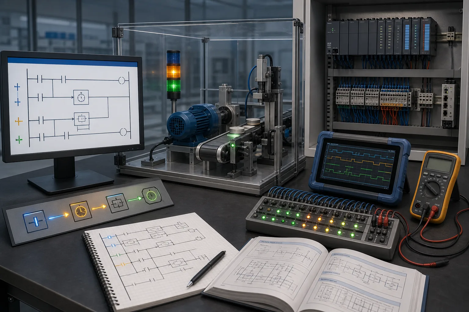
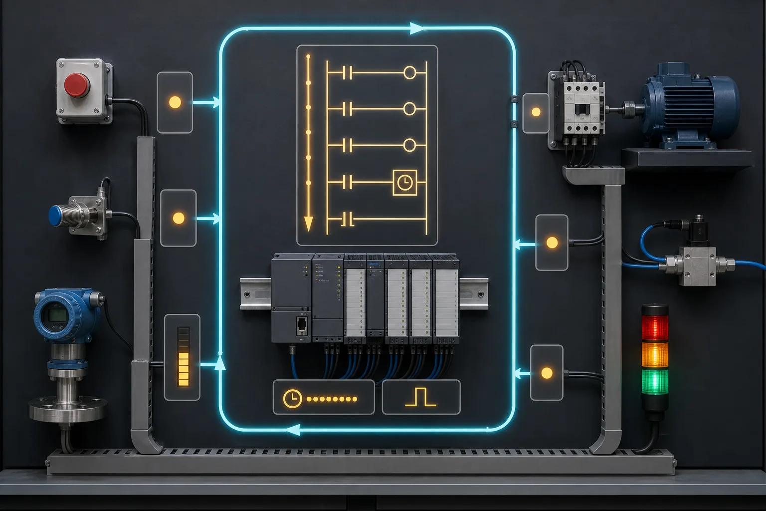
PLC training bench connecting ladder instructions, a guarded machine, live I/O evidence, measurements and a technical manual
Use the evidence-first troubleshooting method
01Separate program syntax from machine behavior and hardware diagnostics; a useful answer preserves all three layers of evidence.
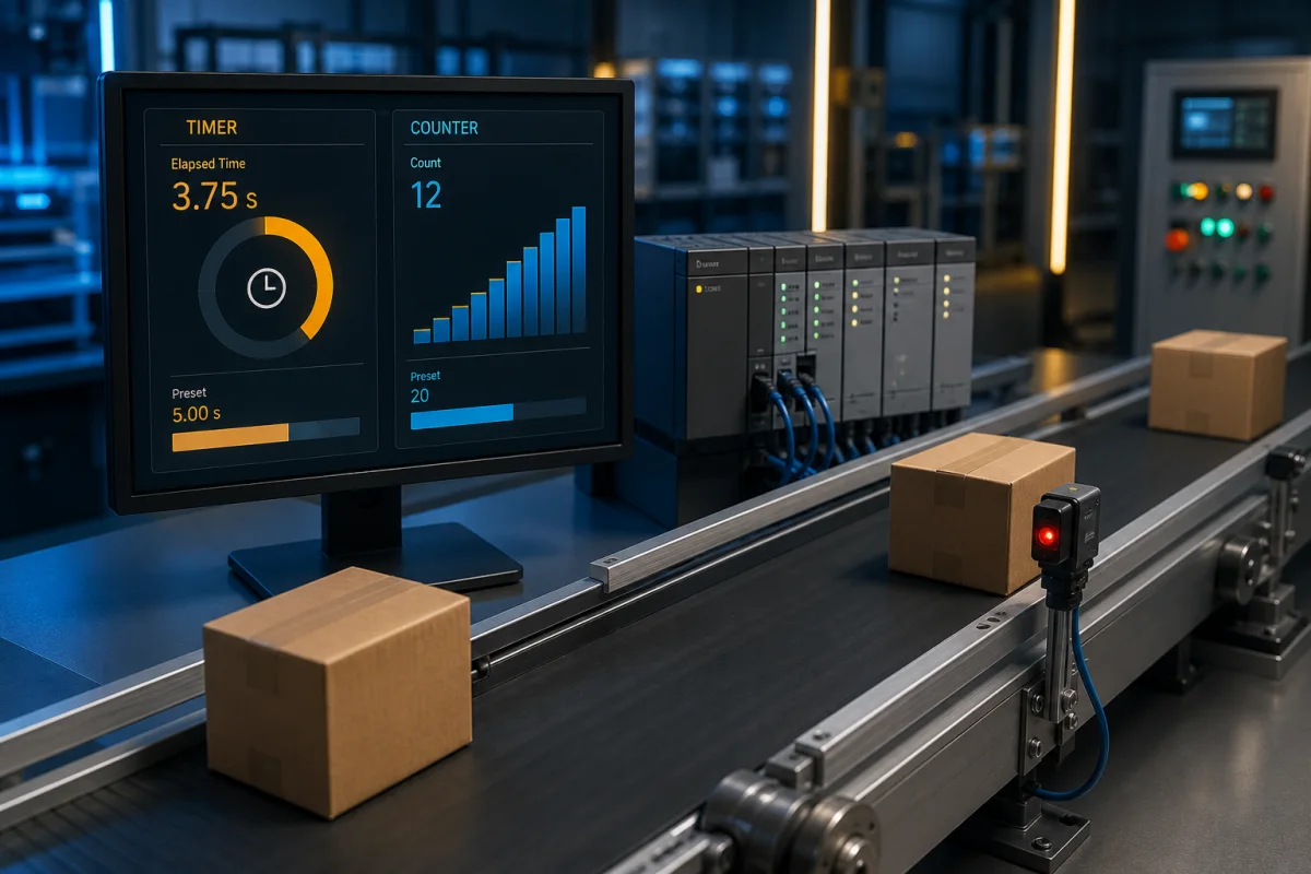
PLC timer and counter instruction path connected to observable machine events
Open the PLC instruction reference
02Read the instruction contract, including timing base, edge behavior and reset conditions, before reusing a mnemonic.
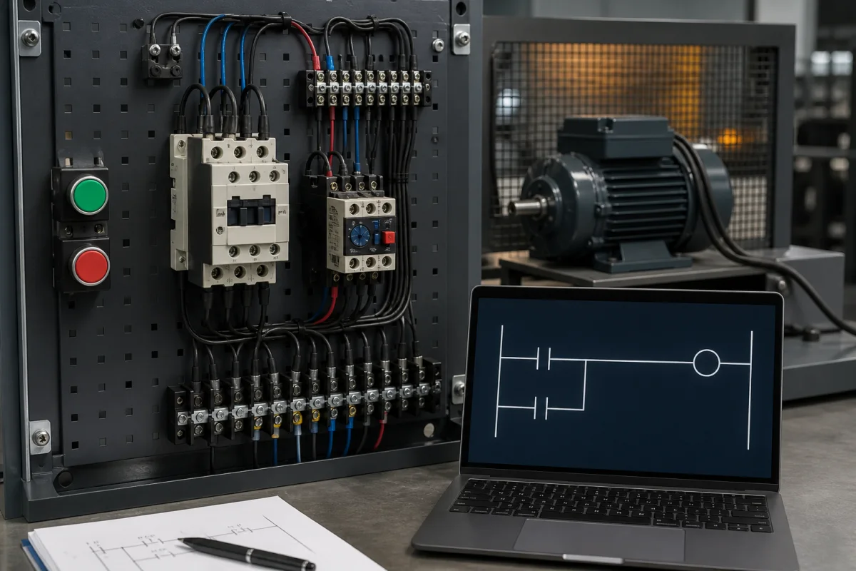
Ladder logic seal-in motor example with start, stop, holding contact and motor output behavior
Study tested ladder logic examples
03A complete pattern combines instructions with permissives, reset behavior and observable tests instead of presenting an isolated code fragment.
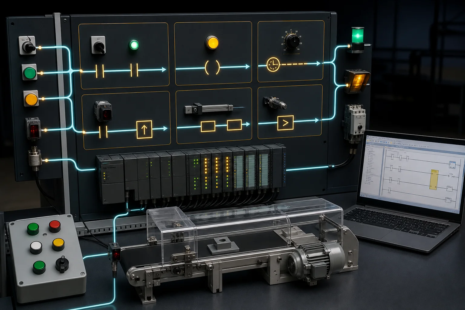
Industrial PLC instruction-family bench connecting contacts, coils, timing, counting, data movement and comparison to physical inputs and outputs
Compare instruction families and syntax
04Instruction families become memorable when each mnemonic is tied to its scan behavior, operands and observable machine result.
PLC scan-cycle evidence board linking field inputs, ladder evaluation, timer and edge state to motor, valve and stack-light outputs
Learn the PLC scan cycle
05Read inputs, solve logic, update outputs and repeat: rung order and retained state explain why correct-looking code can still behave unexpectedly.
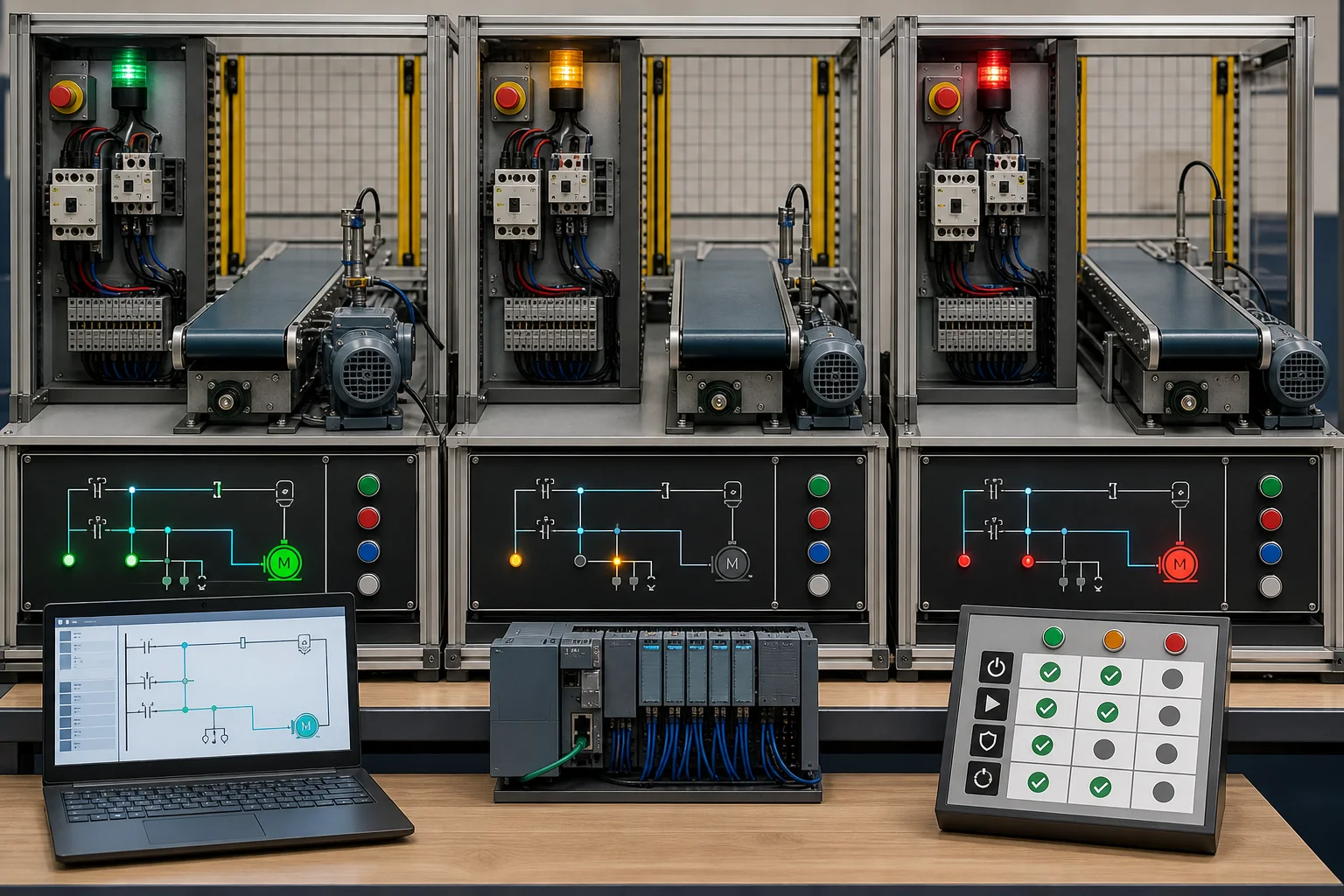
Guarded conveyor and motor control pattern shown under normal start, interlock stop and fault-recovery test states
Run tested ladder logic patterns
06A reusable code pattern is not complete until normal operation, boundary conditions, interlocks and recovery all produce the intended physical outcome.
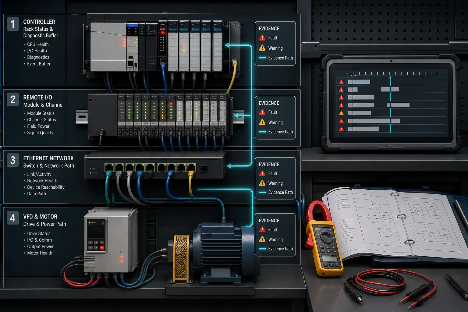
PLC diagnostic workflow separating controller, remote input output, industrial network, drive and motor evidence before consulting the manual
Practise evidence-first fault finding
07Preserve the layer, code, timestamp and active condition first; then use the exact controller, module, network or drive manual for the recovery procedure.

Follow the workflow

Learn one step, use the product, inspect the evidence.

01

Instruction codes

Rockwell-style mnemonic codes include XIC, XIO, OTE, OTL, OTU, ONS, CTU and MOV. IEC systems express similar behaviour with contacts, coils and standard function blocks such as TON, TOF and CTU.

Do this in the product

Open the PLC instruction hub for per-instruction truth tables, syntax notes, examples and runnable scenarios.

Open the exercise
02

Program examples

Useful examples combine instructions into patterns: seal-in motor control, start permissives, alarm latches, pump alternation, traffic-light sequences, counters and analog scaling. The pattern and its edge cases matter more than copying addresses.

Do this in the product

Use the ladder logic examples and PLC projects hubs to open a matching scenario in the simulator.

Open the exercise
03

Fault and diagnostic codes

CPU, I/O, drive and communication fault numbers are vendor-, family- and firmware-specific. Record the exact code, state and timestamp; preserve evidence; then use the manufacturer manual. Never clear a fault repeatedly without finding the cause.

Do this in the product

Practise the evidence workflow in electrical troubleshooting and commissioning scenarios without claiming a generic table replaces the manual.

Open the exercise
04

Portable Structured Text

IEC Structured Text uses statements such as IF, CASE, FOR and function blocks. Vendor environments add libraries and data types, so test portability rather than assuming source code will compile unchanged.

Do this in the product

Compare the same lesson across IEC, Allen-Bradley and Siemens dialect views in the product.

Open the exercise
05

Scan-state and recovery codes

A status bit is only meaningful in context: the input image that was sampled, the rung order, the current timer or counter state, the output update and the task that owns the code. Preserve that state before forcing, resetting or editing anything.

Do this in the product

Run a normal case, an edge case and a recovery case; compare the live I/O and test evidence before accepting the program.

Open the exercise

Field reference

Read the code, predict the scan, prove the result.

These tables separate instruction syntax, reusable control patterns and hardware diagnostics. Use them to choose the right reference before changing a running program.

First identify what “PLC code” means

Searches for PLC codes mix four different jobs. Start here so a ladder mnemonic is not confused with a CPU fault number or a complete control program.

Code typeExamplesUse it forCorrect next step
Instruction mnemonicXIC, XIO, OTE, TON, CTU, MOVBuilding one operation inside ladder or Structured TextCheck operands and scan behavior in the instruction manual, then run a focused test.
Program patternSeal-in, permissive chain, alarm latch, pump alternationCombining instructions into a reusable control behaviorTest normal, boundary, interlock and recovery cases against the machine brief.
Controller or I/O diagnosticMajor fault type/code, module status, channel diagnosticLocating a CPU, task, connection, module or channel problemPreserve the event record and open the manual for the exact controller and firmware.
Drive or field-device faultOvercurrent, undervoltage, encoder, network or thermal tripDiagnosing a VFD, servo, instrument or smart deviceRecord active conditions and use the exact device-family manual; do not substitute a generic list.

PLC instruction codes by scan behavior

Names vary by vendor. The transferable part is the state transition: what is read, what is retained, when an edge is recognized and what must reset.

FamilyCommon codesWhat changes during the scanMinimum proof test
ContactsXIC / XIO; NO / NC contactThe rung condition reads a Boolean tag; the symbol does not change the physical wiring.Toggle the source bit and verify both true and false paths.
OutputsOTE / coil; SET-RESET; OTL / OTUA non-retentive coil follows the solved rung; latch instructions retain state until an explicit reset.Prove de-energization on Stop, interlock and restart.
TimersTON, TOF, TP, RTOElapsed state advances with scan time while enabling conditions and reset rules differ.Test just below, at and just above the preset, then interrupt and restart.
CountersCTU, CTD, CTUD, RESCounts normally change on a qualifying edge, not on every scan that the input remains true.Hold the input true, pulse it repeatedly and verify reset and rollover assumptions.
EdgesONS, OSR, R_TRIG, F_TRIGThe output is true for one execution when the remembered previous state changes.Prove one pulse per transition and verify first-scan behavior.
Compare and limitEQU, NEQ, GRT, LES, LIM; EQ, GT, LTThe rung result depends on type, sign, scaling and boundary inclusion.Test both boundaries, one value outside each side and invalid or stale data.
Data and mathMOV, COP, ADD, SUB, MUL, DIV, SCALEValues change immediately for later rungs in the same task; type conversion can truncate or overflow.Check data types, zero division, range limits and downstream rung order.
Sequence and stateCASE, sequencer, step bits, state machineOnly permitted transitions should advance the process; recovery must return to a defined state.Test every transition, aborted step, power-up state and manual recovery path.

Fault-code evidence workflow

A numeric code without provenance is weak evidence. Capture the surrounding state before changing the plant, then consult the authoritative manual.

LayerCapture before resetLikely evidence sourceUnsafe shortcut to avoid
Controller and taskMode, major/minor class, type/code, task and timestampController fault log, diagnostic buffer and programming manualRepeatedly clearing a major fault without locating the triggering instruction.
Remote I/O and channelModule state, channel state, field power and last known valueModule status page, wiring diagram and module manualAssuming a logic fault when field power or a channel is unhealthy.
Industrial networkLink state, connection status, topology, device reachability and sequence of eventsManaged-switch diagnostics, controller connections and device manualReplacing a device before checking power, cabling, addressing and connection state.
Drive and motorDrive trip, DC bus, current, speed command, thermal state and run sourceExact VFD/servo manual plus measured electrical and mechanical evidenceResetting an overcurrent or thermal trip and immediately restarting the load.
Program behaviorInput image, rung state, retained bits, timer/counter values and commanded outputsOnline monitor, trend, event log and repeatable simulator testTreating an energized output command as proof that the actuator moved safely.

Core concepts

Know what the evidence means.

The simulator creates a repeatable result; these concepts make that result transferable to real vendor software and supervised practical work.

Mnemonic

A short instruction identifier such as XIC or OTE. Meaning and operand rules depend on the platform.

Pattern

A tested arrangement of instructions that solves a recurring control problem, including reset and fault behaviour.

Diagnostic evidence

Code, timestamp, active state, surrounding I/O and preceding event sequence make a fault number actionable.

Scan contract

The same code can produce a different result when rung order, retentive state, edge detection or task timing changes. Predict the scan before editing the pattern.

Common mistakes to avoid

  • × Treating all vendor mnemonics as interchangeable
  • × Copying a latch without a safe reset path
  • × Using a generic fault-code table for real hardware
  • × Publishing a code example without a runnable test
  • × Clearing a fault before preserving its timestamp and active state
  • × Assuming a green rung proves the machine completed the required behavior

Continue in the workspace

Turn this tutorial into retained training evidence.

Run the foundation exercise publicly, then use a subscription for advanced challenges, saved configurations, full attempt history, sharing, assigned paths and team reporting.

Technical reference questions

Questions before you continue.

Common Rockwell mnemonics include XIC, XIO, OTE, OTL, OTU, ONS, CTU, CTD, TON, TOF and MOV. IEC tools may display equivalent standard elements differently.

Technical reference and worked-example guide

PLC codes and examples: implementation, evidence and troubleshooting

Direct answer

PLC codes and examples becomes useful when it connects vendor, controller or device, software, firmware, code text or number, screen, timestamp, operating state and preceding event with observed code through the correct instruction reference, program context or diagnostic manual to an evidence-based next action, then proves one known instruction and one known fault interpreted with source and context retained under normal, boundary, fault and recovery conditions. The objective is a repeatable engineering or learning result, not merely activity inside a page or tool.

This guide is written for learners and technicians trying to distinguish instruction mnemonics, sample logic, controller faults and device diagnostics. The intended result is specific: the reader can classify the code being searched, find its correct owner and verify meaning in the target context.

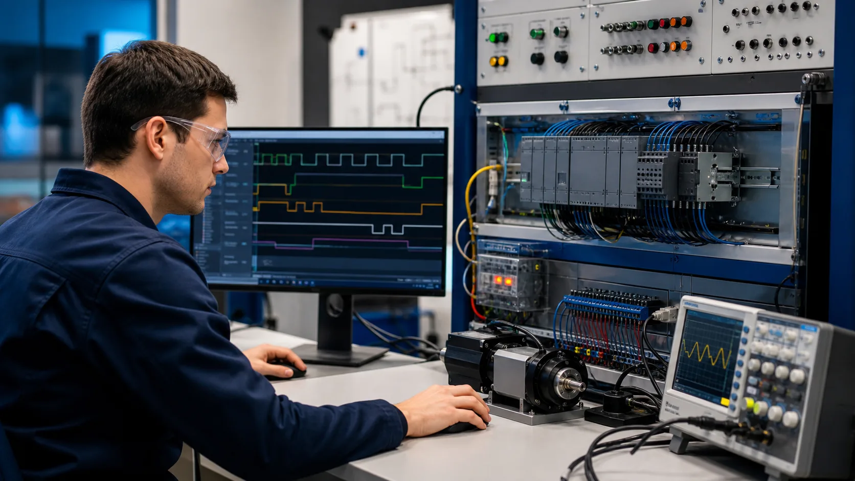
Automation engineer checking PLC signal timelines, executable logic and training-rack behavior for PLC instruction, program and fault-code navigation
Use this physical system view to connect PLC instruction, program and fault-code navigation with observable inputs, control decisions, outputs and verification evidence.

System map / 02

Six concepts that control the result

Treat these as connected checkpoints. Each checkpoint has an expected state, an observable state and a boundary to the next part of the system. That structure prevents a software indication from being mistaken for physical proof.

NODE 01observable

Define the operating contract

vendor, controller or device, software, firmware, code text or number, screen, timestamp, operating state and preceding event. For PLC instruction, program and fault-code navigation, record the initial condition, actor, requested change, observable result and stopping condition before selecting a tool or implementation.

NODE 02observable

Map the evidence path

observed code through the correct instruction reference, program context or diagnostic manual to an evidence-based next action. Separate request, internal state, output or service, physical or user-visible result and independent feedback so each boundary can be inspected.

NODE 03observable

Prove normal operation

one known instruction and one known fault interpreted with source and context retained. Run more than one cycle from a known state and retain the values, timings or artifacts that demonstrate repeatability.

NODE 04observable

Exercise a boundary case

same number across vendors, decimal versus hexadecimal, stale alarm, translated wording, symptom code and undocumented reset. Choose minimum, maximum, simultaneous, delayed or restart conditions that reveal assumptions hidden by the happy path.

NODE 05observable

Diagnose a controlled fault

an identity, context, source, interpretation, program, device or process-response mismatch. Preserve the first symptom, divide the system at a measurable boundary and change one condition only after predicting the result.

NODE 06observable

Transfer and hand over

the conclusion verified in current official documentation and against the actual controller or device state. Restore normal state, remove temporary changes, repeat affected checks and document which claims remain limited to the learning environment.

Procedure / 03

A six-step practice and commissioning workflow

Run the steps in order the first time. Later, the same structure becomes a diagnostic loop: define the expected condition, observe the boundary, interpret the difference and choose one proving action.

  1. 01

    Write the acceptance case

    Convert vendor, controller or device, software, firmware, code text or number, screen, timestamp, operating state and preceding event into initial conditions, one stimulus and observable pass criteria.

    Evidence: Another person can repeat the case without guessing the intended result.

    Avoid: Using page completion or an animation as the acceptance criterion.

  2. 02

    Build the map

    Document observed code through the correct instruction reference, program context or diagnostic manual to an evidence-based next action and name who owns each state or decision.

    Evidence: Every request and result has a source, destination and useful inspection point.

    Avoid: Using the same value as command, status and independent feedback.

  3. 03

    Run the baseline

    Apply one known instruction and one known fault interpreted with source and context retained from a clean start and record the expected evidence.

    Evidence: Repeated runs produce the same bounded result.

    Avoid: Changing several parameters before a baseline exists.

  4. 04

    Challenge assumptions

    Test same number across vendors, decimal versus hexadecimal, stale alarm, translated wording, symptom code and undocumented reset without changing the acceptance contract.

    Evidence: Limits, timing and restart behavior reach defined states.

    Avoid: Testing only one ideal sequence.

  5. 05

    Isolate one failure

    Introduce or analyse an identity, context, source, interpretation, program, device or process-response mismatch and locate the first disagreement.

    Evidence: The proving action distinguishes the leading hypotheses.

    Avoid: Resetting, forcing or replacing before evidence is retained.

  6. 06

    Close the evidence loop

    Complete the conclusion verified in current official documentation and against the actual controller or device state and repeat the affected regression cases.

    Evidence: Reference use is complete when inputs, assumptions, units or initial conditions are recorded and the result is independently checked at a useful boundary.

    Avoid: Treating an acknowledged message or one successful rerun as handover.

Diagnostic matrix / 04

Symptoms, proving points and next actions

The table is a reasoning aid, not a parts-replacement chart. Preserve the initial symptom, inspect the named boundary and use the interpretation to choose the next controlled test. Site safety procedures and equipment manuals remain authoritative.

Diagnostic symptoms, inspection points, interpretations and next actions for PLC codes and examples: implementation, evidence and troubleshooting
Observed symptomInspectInterpretationNext proving action
The expected result is unclearRequirement, initial state, actor, stimulus, units and pass conditionThe technician, programmer and reviewer may be solving different versions of the task.Rewrite one observable acceptance case before continuing.
Internal state changes but the outcome does notRequest, final owner, output or service boundary and independent feedbackA software or interface indication proves intent at one layer, not the complete outcome.Trace the first boundary after the changing state.
Normal case passes but an edge case failsLimits, timing, simultaneous events, reset and restart assumptionsThe implementation contains a hidden assumption exposed by the changed condition.Add the failed boundary as a permanent regression case.
The failure disappears after resetOriginal symptom, histories, diagnostics, timestamps and active causeReset changed evidence or state without proving the initiating cause.Reproduce under a controlled condition and preserve pre/post-event data.
Simulator and target disagreeModel boundary, software version, task timing, I/O behavior, data types and configurationA learning model and the intended target do not share one of the recorded assumptions.Reduce the case and verify against current target documentation.
The result cannot be explainedPrediction, observation, proving action, alternative hypotheses and limitationsActivity occurred but the evidence is not yet transferable or reviewable.Have the learner defend the signal path and repeat a changed case.

Product evidence / 05

What the browser practice can actually demonstrate

The page connects definitions and worked examples to runnable tools, explicit assumptions and repeatable checks so a formula or pattern can be challenged.

Where simulation stops

A mnemonic or numeric code is not universal; manufacturer, controller, module, firmware, screen and operating state determine meaning.

Commissioning notebook / 06

Six cases that turn the concepts into evidence

Use these as written briefs rather than click-through instructions. For every case, state the expected condition before acting, retain the first useful observation and explain why the final result proves the requirement. A different program or component choice can still be correct when it produces the same bounded behavior and evidence.

Case 01

predict → observe → prove

Prove define the operating contract

Engineering context. vendor, controller or device, software, firmware, code text or number, screen, timestamp, operating state and preceding event. For PLC instruction, program and fault-code navigation, record the initial condition, actor, requested change, observable result and stopping condition before selecting a tool or implementation. Begin with a written normal condition and identify which request, state, physical result or communication value will provide independent confirmation. Do not begin by changing the configuration; the initial state is part of the evidence and should remain reproducible.

Controlled setup. Use the “Write the acceptance case” stage of the workflow: convert vendor, controller or device, software, firmware, code text or number, screen, timestamp, operating state and preceding event into initial conditions, one stimulus and observable pass criteria. The acceptance record should show this result: another person can repeat the case without guessing the intended result. Record initial conditions, the exact stimulus and the observation point so another learner can repeat the case without relying on your memory.

Fault challenge. Introduce or analyse “The expected result is unclear” as one bounded deviation. Inspect requirement, initial state, actor, stimulus, units and pass condition The working interpretation is that the technician, programmer and reviewer may be solving different versions of the task. The next proving action is to rewrite one observable acceptance case before continuing. Change only one condition before observing the result, and preserve timestamps or measurements where timing matters.

Review and recovery. The most common trap here is using page completion or an animation as the acceptance criterion. After restoring the cause, repeat the normal case and at least one stop, timeout, disconnect or restart boundary relevant to this topic. Remove temporary forces and bypasses, return the model to a known state and retain the evidence that both operation and recovery are deliberate.

Explain it aloud: What should I learn first about PLC instruction, program and fault-code navigation? A defensible short answer is: Start with the operating contract and evidence path: vendor, controller or device, software, firmware, code text or number, screen, timestamp, operating state and preceding event, followed by observed code through the correct instruction reference, program context or diagnostic manual to an evidence-based next action. Add advanced features only after the baseline is predictable.

Case 02

predict → observe → prove

Prove map the evidence path

Engineering context. observed code through the correct instruction reference, program context or diagnostic manual to an evidence-based next action. Separate request, internal state, output or service, physical or user-visible result and independent feedback so each boundary can be inspected. Begin with a written normal condition and identify which request, state, physical result or communication value will provide independent confirmation. Do not begin by changing the configuration; the initial state is part of the evidence and should remain reproducible.

Controlled setup. Use the “Build the map” stage of the workflow: document observed code through the correct instruction reference, program context or diagnostic manual to an evidence-based next action and name who owns each state or decision. The acceptance record should show this result: every request and result has a source, destination and useful inspection point. Record initial conditions, the exact stimulus and the observation point so another learner can repeat the case without relying on your memory.

Fault challenge. Introduce or analyse “Internal state changes but the outcome does not” as one bounded deviation. Inspect request, final owner, output or service boundary and independent feedback The working interpretation is that a software or interface indication proves intent at one layer, not the complete outcome. The next proving action is to trace the first boundary after the changing state. Change only one condition before observing the result, and preserve timestamps or measurements where timing matters.

Review and recovery. The most common trap here is using the same value as command, status and independent feedback. After restoring the cause, repeat the normal case and at least one stop, timeout, disconnect or restart boundary relevant to this topic. Remove temporary forces and bypasses, return the model to a known state and retain the evidence that both operation and recovery are deliberate.

Explain it aloud: How do I practise PLC instruction, program and fault-code navigation effectively? A defensible short answer is: Use short cases with known initial conditions, a written prediction, one action and an observable result. Then alter a boundary or fault and explain why the evidence changed.

Case 03

predict → observe → prove

Prove prove normal operation

Engineering context. one known instruction and one known fault interpreted with source and context retained. Run more than one cycle from a known state and retain the values, timings or artifacts that demonstrate repeatability. Begin with a written normal condition and identify which request, state, physical result or communication value will provide independent confirmation. Do not begin by changing the configuration; the initial state is part of the evidence and should remain reproducible.

Controlled setup. Use the “Run the baseline” stage of the workflow: apply one known instruction and one known fault interpreted with source and context retained from a clean start and record the expected evidence. The acceptance record should show this result: repeated runs produce the same bounded result. Record initial conditions, the exact stimulus and the observation point so another learner can repeat the case without relying on your memory.

Fault challenge. Introduce or analyse “Normal case passes but an edge case fails” as one bounded deviation. Inspect limits, timing, simultaneous events, reset and restart assumptions The working interpretation is that the implementation contains a hidden assumption exposed by the changed condition. The next proving action is to add the failed boundary as a permanent regression case. Change only one condition before observing the result, and preserve timestamps or measurements where timing matters.

Review and recovery. The most common trap here is changing several parameters before a baseline exists. After restoring the cause, repeat the normal case and at least one stop, timeout, disconnect or restart boundary relevant to this topic. Remove temporary forces and bypasses, return the model to a known state and retain the evidence that both operation and recovery are deliberate.

Explain it aloud: What counts as proof of competence? A defensible short answer is: A repeatable artifact or system result plus an explanation of the signal path is stronger than time spent, screenshots or a copied answer. Physical competence requires separate supervised evidence.

Case 04

predict → observe → prove

Prove exercise a boundary case

Engineering context. same number across vendors, decimal versus hexadecimal, stale alarm, translated wording, symptom code and undocumented reset. Choose minimum, maximum, simultaneous, delayed or restart conditions that reveal assumptions hidden by the happy path. Begin with a written normal condition and identify which request, state, physical result or communication value will provide independent confirmation. Do not begin by changing the configuration; the initial state is part of the evidence and should remain reproducible.

Controlled setup. Use the “Challenge assumptions” stage of the workflow: test same number across vendors, decimal versus hexadecimal, stale alarm, translated wording, symptom code and undocumented reset without changing the acceptance contract. The acceptance record should show this result: limits, timing and restart behavior reach defined states. Record initial conditions, the exact stimulus and the observation point so another learner can repeat the case without relying on your memory.

Fault challenge. Introduce or analyse “The failure disappears after reset” as one bounded deviation. Inspect original symptom, histories, diagnostics, timestamps and active cause The working interpretation is that reset changed evidence or state without proving the initiating cause. The next proving action is to reproduce under a controlled condition and preserve pre/post-event data. Change only one condition before observing the result, and preserve timestamps or measurements where timing matters.

Review and recovery. The most common trap here is testing only one ideal sequence. After restoring the cause, repeat the normal case and at least one stop, timeout, disconnect or restart boundary relevant to this topic. Remove temporary forces and bypasses, return the model to a known state and retain the evidence that both operation and recovery are deliberate.

Explain it aloud: Why test faults and restart behavior? A defensible short answer is: Because an identity, context, source, interpretation, program, device or process-response mismatch or same number across vendors, decimal versus hexadecimal, stale alarm, translated wording, symptom code and undocumented reset can expose assumptions that never appear during ideal startup and steady operation.

Case 05

predict → observe → prove

Prove diagnose a controlled fault

Engineering context. an identity, context, source, interpretation, program, device or process-response mismatch. Preserve the first symptom, divide the system at a measurable boundary and change one condition only after predicting the result. Begin with a written normal condition and identify which request, state, physical result or communication value will provide independent confirmation. Do not begin by changing the configuration; the initial state is part of the evidence and should remain reproducible.

Controlled setup. Use the “Isolate one failure” stage of the workflow: introduce or analyse an identity, context, source, interpretation, program, device or process-response mismatch and locate the first disagreement. The acceptance record should show this result: the proving action distinguishes the leading hypotheses. Record initial conditions, the exact stimulus and the observation point so another learner can repeat the case without relying on your memory.

Fault challenge. Introduce or analyse “Simulator and target disagree” as one bounded deviation. Inspect model boundary, software version, task timing, I/O behavior, data types and configuration The working interpretation is that a learning model and the intended target do not share one of the recorded assumptions. The next proving action is to reduce the case and verify against current target documentation. Change only one condition before observing the result, and preserve timestamps or measurements where timing matters.

Review and recovery. The most common trap here is resetting, forcing or replacing before evidence is retained. After restoring the cause, repeat the normal case and at least one stop, timeout, disconnect or restart boundary relevant to this topic. Remove temporary forces and bypasses, return the model to a known state and retain the evidence that both operation and recovery are deliberate.

Explain it aloud: Can browser practice replace official software or hardware? A defensible short answer is: No. It can build concepts and diagnostic reasoning. Exact firmware, I/O electrical behavior, networking, safety and commissioning require current official tools, documentation and target equipment.

Case 06

predict → observe → prove

Prove transfer and hand over

Engineering context. the conclusion verified in current official documentation and against the actual controller or device state. Restore normal state, remove temporary changes, repeat affected checks and document which claims remain limited to the learning environment. Begin with a written normal condition and identify which request, state, physical result or communication value will provide independent confirmation. Do not begin by changing the configuration; the initial state is part of the evidence and should remain reproducible.

Controlled setup. Use the “Close the evidence loop” stage of the workflow: complete the conclusion verified in current official documentation and against the actual controller or device state and repeat the affected regression cases. The acceptance record should show this result: reference use is complete when inputs, assumptions, units or initial conditions are recorded and the result is independently checked at a useful boundary. Record initial conditions, the exact stimulus and the observation point so another learner can repeat the case without relying on your memory.

Fault challenge. Introduce or analyse “The result cannot be explained” as one bounded deviation. Inspect prediction, observation, proving action, alternative hypotheses and limitations The working interpretation is that activity occurred but the evidence is not yet transferable or reviewable. The next proving action is to have the learner defend the signal path and repeat a changed case. Change only one condition before observing the result, and preserve timestamps or measurements where timing matters.

Review and recovery. The most common trap here is treating an acknowledged message or one successful rerun as handover. After restoring the cause, repeat the normal case and at least one stop, timeout, disconnect or restart boundary relevant to this topic. Remove temporary forces and bypasses, return the model to a known state and retain the evidence that both operation and recovery are deliberate.

Explain it aloud: How should progress be documented? A defensible short answer is: Keep the requirement, initial state, program or configuration, observed values, fault hypothesis, proving action, recovery result and a concise limitations statement.

Answer surface / 07

Questions people ask about PLC codes and examples

These concise answers define the operating, training and product boundaries most often missed in broad summaries. The full workflow and diagnostic table above provide the evidence behind them.

What should I learn first about PLC instruction, program and fault-code navigation?

Start with the operating contract and evidence path: vendor, controller or device, software, firmware, code text or number, screen, timestamp, operating state and preceding event, followed by observed code through the correct instruction reference, program context or diagnostic manual to an evidence-based next action. Add advanced features only after the baseline is predictable.

How do I practise PLC instruction, program and fault-code navigation effectively?

Use short cases with known initial conditions, a written prediction, one action and an observable result. Then alter a boundary or fault and explain why the evidence changed.

What counts as proof of competence?

A repeatable artifact or system result plus an explanation of the signal path is stronger than time spent, screenshots or a copied answer. Physical competence requires separate supervised evidence.

Why test faults and restart behavior?

Because an identity, context, source, interpretation, program, device or process-response mismatch or same number across vendors, decimal versus hexadecimal, stale alarm, translated wording, symptom code and undocumented reset can expose assumptions that never appear during ideal startup and steady operation.

Can browser practice replace official software or hardware?

No. It can build concepts and diagnostic reasoning. Exact firmware, I/O electrical behavior, networking, safety and commissioning require current official tools, documentation and target equipment.

How should progress be documented?

Keep the requirement, initial state, program or configuration, observed values, fault hypothesis, proving action, recovery result and a concise limitations statement.

What should I do when the answer differs from a guide?

Check assumptions, version, units and initial state first. Reduce the case, compare one boundary at a time and prefer current primary documentation for target-specific behavior.

When is a PLC instruction, program and fault-code navigation exercise finished?

Reference use is complete when inputs, assumptions, units or initial conditions are recorded and the result is independently checked at a useful boundary.