
Delta DVP-style mnemonic practice guide
Delta PLC simulator: DVP devices, octal I/O, TMR and CNT in the browser
Direct answer
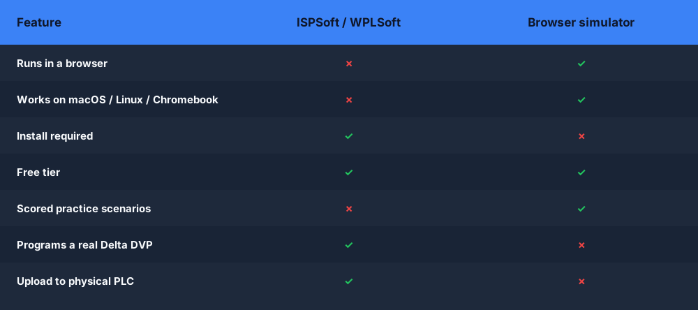
A Delta PLC simulator in the browser lets you practice DVP-style instruction lists, X inputs, Y outputs, M relays, D registers and T and C devices without installing WPLSoft or ISPSoft. It runs a tested subset of mnemonics on a training engine, not Delta firmware, so finished logic must be rebuilt and verified in the official tool for the exact CPU.
This guide is written for technicians, students and OEM machine builders meeting Delta DVP controllers who want to read and write the mnemonic form of X, Y, M, D, T and C logic before arranging a Windows engineering environment. The intended result is specific: the learner can write a seal-in, a timed step and a counted batch in Delta-style mnemonics, explain octal I/O numbering and K presets, and list which details must be rechecked in the Delta manual for the target CPU.
Octal X and Y numbering
On DVP controllers, input and output points are numbered in octal: X0 to X7, then X10 to X17, with no X8 or X9. The simulator follows the same grouping and treats X10 as the first point of the second group of eight, so an address ending in 8 or 9 is rejected at compile time.
Device families
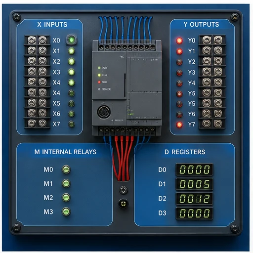
X devices are inputs, Y devices are outputs, M devices are internal auxiliary relays, D devices are 16-bit data registers, and T and C devices are timers and counters. Unlike X and Y, M, D, T and C numbers are decimal. In this browser, M bits and D words are internal values with no physical I/O behind them.
Mnemonic rungs
Every rung starts with LD for a normally open condition or LDI for a normally closed one, adds series terms with AND and ANI and parallel terms with OR and ORI, then ends with OUT, SET or RST. Reading and writing this list form is the core skill a DVP technician uses when viewing an instruction-list program.
K and H constants
Delta writes decimal constants with a K prefix and hexadecimal constants with H. In this simulator, K values supply timer and counter presets and math operands, while hexadecimal H constants are outside the tested subset. A preset written without its prefix is rejected with a message rather than silently read as a device address.
TMR time base
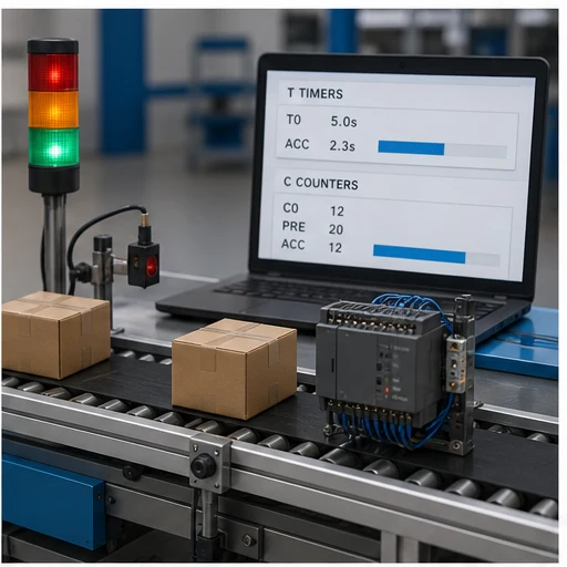
TMR T0 K50 starts an on-delay timer whose preset is multiplied by the time base. The browser fixes every T device at 100 ms, so K50 means five seconds. On a real DVP the resolution depends on which T number range you use and on the CPU series, so confirm it in the manual before copying presets.
CNT and counter reset
CNT C0 K10 counts rising transitions of its driving logic until the count reaches ten, then its contact turns on. RST C0 clears both count and contact. The simulator merges an RST line into the matching CNT, so the CNT must appear first; retentive counter ranges and 32-bit counters on real controllers are not modeled.
- 01
Fix the target context
Record the DVP series and CPU you are preparing for, and note whether the job uses WPLSoft, ISPSoft or another Delta tool.
Evidence: The practice file header names the target, so every later assumption can be checked against its manual.
Avoid: Treating one generic DVP example as valid for every Delta controller family.
- 02
Draw the I/O list in octal
Assign buttons, sensors and loads to X and Y points using octal numbering, and reserve M relays for internal state.
Evidence: No address ends in 8 or 9, and every field point has one clear role.
Avoid: Numbering the ninth input X8 because decimal counting feels natural.
- 03
Write the seal-in
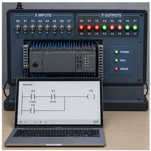
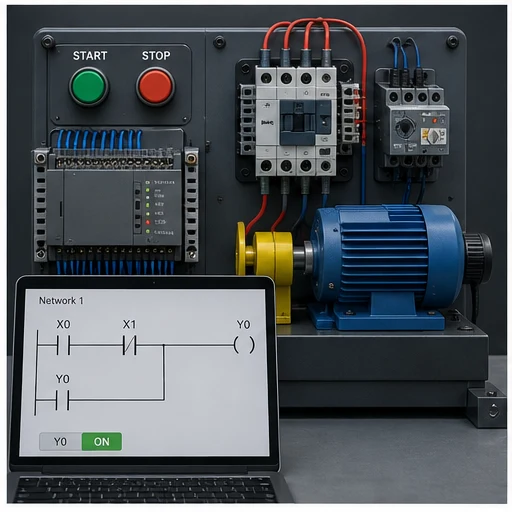
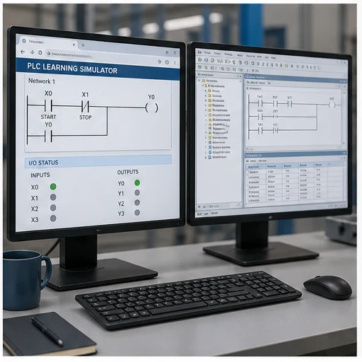
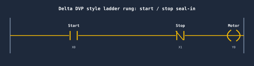
Enter LD X0, OR Y0, ANI X1, OUT Y0 and run it, pressing start and then stop.
Evidence: Y0 stays on after X0 releases and drops when X1 goes true.
Avoid: Wiring the stop logic with AND so the motor only runs while stop is pressed.
- 04
Add a timed step
Drive TMR T0 K30 from Y0 and use the T0 contact to enable a second output.
Evidence: The second output turns on three seconds after Y0 and drops as soon as Y0 turns off.
Avoid: Expecting the preset to mean three seconds on a real DVP without checking the time base.
- 05
Count and reset a batch
Drive CNT C0 K5 from a product sensor, use C0 to stop the conveyor, then add an RST C0 rung after it.
Evidence: The fifth pulse stops the conveyor and the reset input restarts the batch count at zero.
Avoid: Placing the RST C0 rung before the CNT rung, which the parser cannot merge.
- 06
Rebuild on the target
Recreate the program in the Delta tool the CPU requires, monitor it online and repeat each test.
Evidence: Device ranges, time bases and upload behavior match the manual for the actual controller.
Avoid: Copying mnemonics across and assuming identical behavior without a monitored retest.
| Observed symptom | Inspect | Interpretation | Next proving action |
|---|---|---|---|
| Compile error on X8 or Y9 | The address digits and how the I/O list was numbered | DVP I/O is octal, so the point after X7 is X10; the parser refuses a final digit of 8 or 9 rather than guessing a mapping. | Renumber the I/O list in octal and update every reference to it. |
| Second OUT after one condition fails to compile | Whether two coils follow a single LD block with nothing between them | Each OUT, SET or RST closes the rung in this subset, so a second coil has no open condition and MPS-style branching is not supported. | Repeat the condition with its own LD line, or drive an M relay once and use it for both outputs. |
| Timer finishes at an unexpected time | The K preset, the 100 ms browser time base and the T number range in the target manual | K50 is five seconds here, but a real DVP can give different T ranges different resolutions, so the same line may run faster or slower. | Convert the required delay using the target time base and retest online. |
| RST T0 is rejected | The rung that tries to reset the timer and the logic driving TMR T0 | The browser timer is an on-delay block reset by removing its input, so a direct timer reset instruction is outside the supported subset. | Make the timer input go false to reset it here, and use the controller manual for RST T on real hardware. |
| Counter never reaches preset | The CNT driving logic, whether the sensor produces separate transitions and any RST C rung that stays true | The counter advances on transitions of its input; a held input or an active reset line keeps the count from climbing. | Toggle the sensor cleanly and confirm the reset condition is false while counting. |
| ORB, ANB or LDP rejected at compile time | Which instructions the program relies on beyond the tested subset | Block-combine, stack and edge-contact instructions exist on DVP controllers but are not implemented in this browser dialect. | Restructure with M relays for practice, or move the logic to the official Delta tool to use those instructions. |
Product evidence / 05
What the browser practice can actually demonstrate
The Delta dialect parser accepts LD, LDI, AND, ANI, OR, ORI, OUT, SET and RST, plus TMR, CNT, MOV, ADD, SUB, MUL and DIV. It maps X and Y into octal-style groups of eight, rejects digits 8 and 9 in those addresses, and reports unsupported block and stack instructions as compile errors instead of guessing.
Why do Delta DVP inputs skip X8 and X9?
DVP X and Y points are numbered in octal, so each group runs 0 to 7 and the next starts at 10. X7 is followed by X10. M, D, T and C devices are numbered in decimal. The simulator applies the same octal rule to X and Y and rejects any address whose last digit is 8 or 9.
What does TMR T0 K50 mean in Delta PLC programming?
TMR starts timer T0 with a decimal preset of 50 time-base units. In this browser every T device uses a 100 ms base, so K50 equals five seconds. On a real DVP the time base depends on the timer number range and CPU series, so check the programming manual before relying on a preset.
What is the difference between LD and LDI on a Delta PLC?
LD starts a rung with a normally open contact, true when the device is on. LDI starts it with a normally closed contact, true when the device is off. AND and ANI, and OR and ORI, apply the same open and closed pairing to series and parallel conditions.
How do SET and RST differ from OUT in Delta mnemonics?
OUT writes the rung result to the device on every scan, so it turns off when the condition goes false. SET turns the device on and leaves it on; RST turns it off. A SET without a matching RST path keeps a device latched after the start condition disappears.
Is WPLSoft or ISPSoft better for learning Delta PLCs?
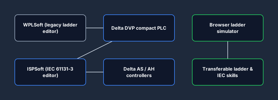
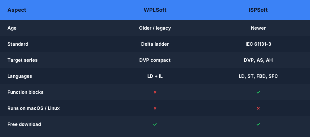
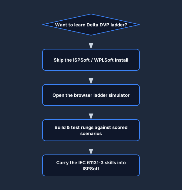
Choose by controller, not preference. WPLSoft is the older tool used with many DVP models, while ISPSoft uses an IEC 61131-3 project model and is listed for DVP, AS and AH applications. The browser teaches mnemonics that both environments use, but project setup must follow the target CPU documentation.
Can I use M, D, T and C devices in the browser Delta simulator?
Yes, within a tested subset. M bits work as internal relays, D registers hold integer values for MOV and arithmetic, and T and C devices come from TMR and CNT instructions. Latched ranges, special relays and 32-bit counters that exist on real DVP models are not modeled.
Why does my math instruction fail after an LD line?
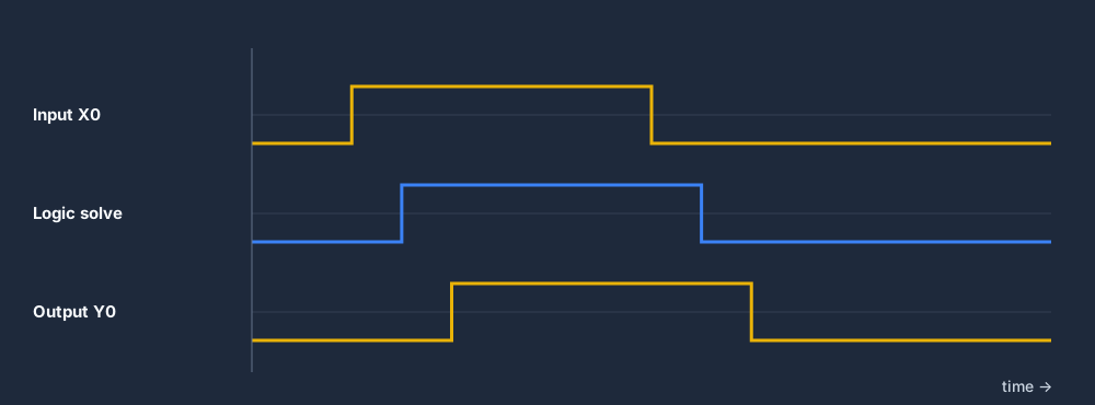
In this simulator MOV, ADD, SUB, MUL and DIV run as standalone lines every scan, and a leading LD condition raises a compile error. On a DVP these instructions are normally driven by a contact. Practice the operand order here, then add the enabling condition when you rebuild the rung in Delta software.
Can I import the browser program into ISPSoft or a DVP?
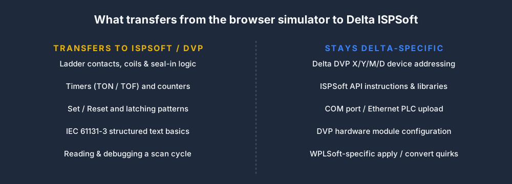
No. There is no project export or hardware connection. Retype the mnemonics or ladder in the Delta tool for your CPU, adjust device ranges and time bases from its manual, then monitor the program online and repeat the same start, stop, timer and counter tests.