PLC Simulator
Browser-based GX-style practiceSimulator guide

Mitsubishi PLC Simulator for GX-Style Logic Practice

Run Mitsubishi-style contacts, coils, latches and device addresses in a browser training runtime. Use it to rehearse logic—not to emulate a MELSEC CPU or replace GX Works commissioning.

Independent learning tool. No hardware connection, vendor project import or controller download. Technical scope verified August 7, 2026.

Program memory
Mitsubishi mnemonic
; X0 sets M0, X1 resets itLD   X0SET  M0LD   X1RST  M0LD   M0OUT  Y0
INPUTOUTPUT

What runs in the browser

Every capability below is tied to the current parser instead of a generic vendor claim.

  • GX-style mnemonic source
  • Live scan-cycle execution
  • M relay latch practice
  • No installation or project file required
Real Mitsubishi PLC simulator footage

See this exact skill in the working simulator.

Watch the real browser product respond to the task on this page, then try the same practical workflow yourself. No slides, concept mockups, install, or credit card.

Try this in the browser
Mitsubishi PLC Simulator — Practise GX Works-Style Ladder Logic

Six Mitsubishi simulation skills in context

Make X, Y, M, D, T and C devices observable

The browser runtime is most useful when each device has a visible purpose. Follow the training sequence from I/O and memory mapping through motor, conveyor and analog-process exercises, then hand the proven reasoning to the correct GX Works project.

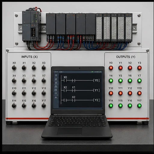
Generic PLC simulator training bench with X input switches, Y output indicators and Mitsubishi-style mnemonic logic
01Toggle one X input at a time and compare the predicted result with the Y output indicators after the scan.
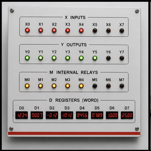
Training board separating X inputs, Y outputs, M internal relays and D data registers
02Keep field I/O, internal bits and word data separate before tracing a program with mixed device families.
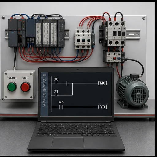
Motor control PLC training rig demonstrating an internal M relay latch and Y motor output
03Set and reset an M relay, then mirror that internal state to the Y output that represents the motor circuit.
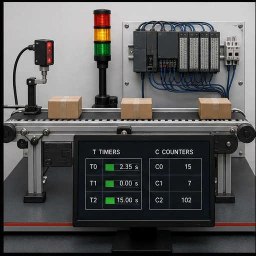
Conveyor PLC simulation lab showing T timer and C counter status beside a photoelectric sensor
04Attach T and C devices to observable conveyor events so preset, accumulated and done behavior has a practical meaning.
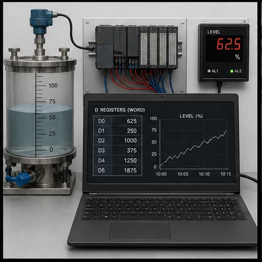
Process level training bench using D registers and a trend to verify PLC data operations
05Move and calculate D-register values, then verify that the number agrees with the simulated process state.
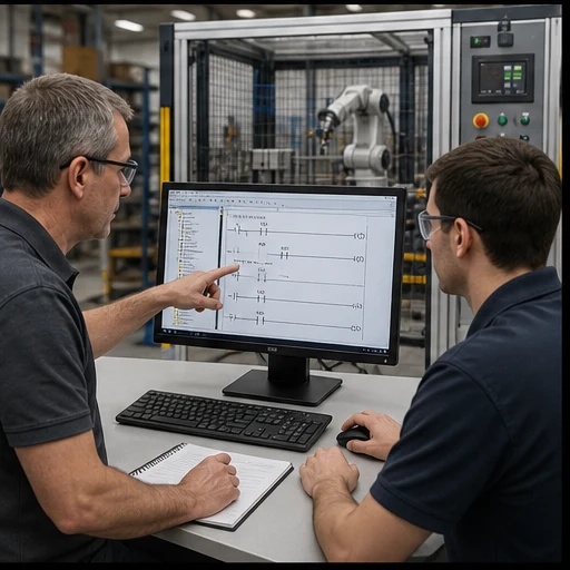
Instructor and learner validating PLC logic at an engineering workstation beside a guarded automation cell
06Rebuild the exercise in the correct GX Works project and validate controller-specific behavior before commissioning.

What this Mitsubishi PLC simulator is designed to do

The fastest way to learn a vendor dialect is to make small programs observable. Here you can write the supported Mitsubishi mnemonic subset, run it against the training engine, and see how input conditions affect internal memory and outputs.

That is intentionally narrower than a vendor emulator. The page does not promise CPU firmware fidelity, special function modules, network configuration or a GX Works project workflow.

Address translation sheet

Read the memory map before the rung

These are the address forms this learning runtime recognises. The final column states the simulator behavior, including intentional simplifications.

Device / areaRoleExampleBrowser behavior
X / YBrowser I/OX0 → Y0Decimal bit mapping connects the mnemonic devices to the training I/O bus.
MInternal stateSET M0 / RST M0Persists latch state between scans until reset.
DInteger dataMOV K25 D0Basic move and arithmetic instructions operate on word-backed registers.
TOn-delay timingOUT T0 K30Runs with a documented fixed 100 ms preset base.
CUp countingOUT C0 K10Counts rising events to a literal preset and exposes the done state.

Executable now

Supported instruction groups

Boolean logic
LD, LDI, AND, ANI, OR, ORI, ANB and ORB
Outputs and state
OUT, SET and RST
Sequence devices
TON-style T devices and CTU-style C devices
Word operations
MOV, ADD, SUB, MUL and DIV

Do not assume

Not in the current subset

  • GX Works project import or export
  • MPS, MRD and MPP
  • Special relays, intelligent modules and positioning instructions
  • Physical PLC communications, forced I/O or safety validation

Choose the right simulator

Browser practice vs official engineering simulation

Both are useful, but they answer different questions. Start here to make the logic observable; use the vendor environment to validate a real controller project.

DecisionThis browser simulatorOfficial vendor environment
Primary jobLearn syntax and scan behavior quicklyEngineer a project for a selected controller
Runtime scopeThe exact subset published on this pageController- and version-specific implementation
Project formatText exercises inside the training appNative vendor project, libraries and configuration
Hardware transferNot supportedUpload, download and online diagnostics

Worked example

A latched Mitsubishi internal relay

Three small rungs make the state visible: one sets M0, one resets it, and the last mirrors the relay to Y0. The example is parser-valid.

Run your own program
Mitsubishi mnemonicParser-valid example
; X0 sets M0, X1 resets it
LD   X0
SET  M0
LD   X1
RST  M0
LD   M0
OUT  Y0

Learning sequence

Use simulation as a short feedback loop

  1. 01

    Predict

    Write down which devices should be true before running a scan.

  2. 02

    Toggle

    Change X inputs one at a time and observe M and Y state.

  3. 03

    Explain

    Describe why a latch persisted or a timer reached its done state.

  4. 04

    Transfer

    Rebuild the same behavior in GX Works and validate it on the correct target.

Engineering boundary

The word “simulator” has a boundary

This is a logic-learning simulator with Mitsubishi syntax support. It is not an official MELSEC simulator and cannot establish equivalence with a selected CPU.

  • Use the support table as the executable contract.
  • Treat timing and X/Y mapping as training-runtime behavior.
  • Test the final program with Mitsubishi’s tools and the real controller.

Technical evidence

Sources and verification

Page claims and the simulator support matrix were reviewed against the production parser and these primary technical sources on August 7, 2026.

Questions

Mitsubishi PLC Simulator for GX-Style Logic Practice FAQ

No. It is an independent browser learning runtime with a Mitsubishi-style parser. It does not emulate a selected MELSEC CPU or replace Mitsubishi’s engineering tools.

Run a Mitsubishi-style program without an install

Start with a small latch, watch the state change, and build toward timers, counters and data operations.

Vendor-dialect field guide

Mitsubishi PLC simulator: memory, workflow and tested boundaries

Direct answer

Mitsubishi PLC simulator begins with an accurate memory and I/O model. Learn X/Y/M/D/T/C device-oriented examples with monitored state. Build a small observable program, monitor the exact devices over scans and verify target-specific syntax, retentive behavior and download procedure in the official environment.

This guide is written for learners transferring vendor-neutral PLC reasoning into a named controller ecosystem without confusing mnemonic familiarity with full platform competence. The intended result is specific: the learner can read common Mitsubishi-style addresses, trace a start/stop or timed sequence and explain which behaviors still require the exact controller and engineering software.

System map / 02

Six concepts that control the result

Treat these as connected checkpoints. Each checkpoint has an expected state, an observable state and a boundary to the next part of the system. That structure prevents a software indication from being mistaken for physical proof.

NODE 01observable

Device and address

Separate physical I/O, internal Boolean state, numeric data, timer/counter state and special/system areas within X/Y/M/D/T/C device-oriented examples with monitored state.

NODE 02observable

Program scan

Follow the same input-read, logic-execution and output-update reasoning while confirming platform-specific task and refresh details.

NODE 03observable

Symbolic naming

Use meaningful symbols and comments even when maintenance requires device addresses to remain visible.

NODE 04observable

Retentive state

Confirm which areas and instructions retain state through mode change or power cycle for the exact CPU configuration.

NODE 05observable

Online observation

Monitor device state to compare input, logic result, output command and feedback without treating a forced value as normal operation.

NODE 06observable

Transfer boundary

Use a learning subset rather than GX Works or MELSEC CPU emulation; repeat syntax, compile, download, timing and I/O tests before real deployment.

Procedure / 03

A six-step practice and commissioning workflow

Run the steps in order the first time. Later, the same structure becomes a diagnostic loop: define the expected condition, observe the boundary, interpret the difference and choose one proving action.

  1. 01

    Choose the CPU context

    Record controller family, software and firmware assumptions.

    Evidence: The exercise has a target boundary.

    Avoid: Writing “all models” instructions.

  2. 02

    Map the devices

    Assign the example using X/Y/M/D/T/C device-oriented examples with monitored state.

    Evidence: Every address has one engineering role.

    Avoid: Reusing a device for unrelated state.

  3. 03

    Write normal behavior

    Build one start/stop or sequence requirement.

    Evidence: The program is readable and observable.

    Avoid: Translating mnemonics without intent.

  4. 04

    Monitor scans

    Toggle inputs and watch devices, timers and outputs.

    Evidence: State matches the predicted table.

    Avoid: Using force as permanent logic.

  5. 05

    Test reset and restart

    Exercise stop, fault, mode change and initialization.

    Evidence: Retained and cleared state is explicit.

    Avoid: Assuming simulator persistence matches CPU memory.

  6. 06

    Verify officially

    Open the equivalent project in the supported vendor tool and hardware path.

    Evidence: Compile and runtime evidence is target-specific.

    Avoid: Treating browser success as commissioning.

Diagnostic matrix / 04

Symptoms, proving points and next actions

The table is a reasoning aid, not a parts-replacement chart. Preserve the initial symptom, inspect the named boundary and use the interpretation to choose the next controlled test. Site safety procedures and equipment manuals remain authoritative.

Diagnostic symptoms, inspection points, interpretations and next actions for Mitsubishi PLC simulator: memory, workflow and tested boundaries
Observed symptomInspectInterpretationNext proving action
Input address never changesPhysical mapping, channel/device address, refresh and force stateThe program may read a different device than the wired point.Verify the hardware map.
Internal bit changes unexpectedlyEvery writer, special-area overlap and initializationMemory ownership is unclear.Cross-reference writes.
Timer behavior differsTime base, instance/device, retentive semantics and task timingSimilar mnemonics can have platform differences.Use the exact instruction help.
Value is corruptRegister width, signedness, word order and conversionThe same device words can represent different types.Inspect typed interpretation.
Download/run differsCPU mode, compile warnings, retained values and I/O refreshEditor simulation did not reproduce controller state.Repeat on a controlled target.
Fault returns after resetActive cause, diagnostic buffer and reset permissivesReset is not removal of cause.Read the official diagnostic record.

Product evidence / 05

What the browser practice can actually demonstrate

The browser dialect page provides parser-tested examples, mapped memory concepts, runnable scenarios and an explicit boundary: a learning subset rather than GX Works or MELSEC CPU emulation.

Where simulation stops

Manufacturer names identify the learning context; they do not imply affiliation, certification or exact emulation. Hardware selection, project conversion, communications, firmware and safety behavior require the official manuals and target equipment.

Commissioning notebook / 06

Six cases that turn the concepts into evidence

Use these as written briefs rather than click-through instructions. For every case, state the expected condition before acting, retain the first useful observation and explain why the final result proves the requirement. A different program or component choice can still be correct when it produces the same bounded behavior and evidence.

Case 01

predict → observe → prove

Prove device and address

Engineering context. Separate physical I/O, internal Boolean state, numeric data, timer/counter state and special/system areas within X/Y/M/D/T/C device-oriented examples with monitored state. Begin with a written normal condition and identify which request, state, physical result or communication value will provide independent confirmation. Do not begin by changing the configuration; the initial state is part of the evidence and should remain reproducible.

Controlled setup. Use the “Choose the CPU context” stage of the workflow: record controller family, software and firmware assumptions. The acceptance record should show this result: the exercise has a target boundary. Record initial conditions, the exact stimulus and the observation point so another learner can repeat the case without relying on your memory.

Fault challenge. Introduce or analyse “Input address never changes” as one bounded deviation. Inspect physical mapping, channel/device address, refresh and force state The working interpretation is that the program may read a different device than the wired point. The next proving action is to verify the hardware map. Change only one condition before observing the result, and preserve timestamps or measurements where timing matters.

Review and recovery. The most common trap here is writing “all models” instructions. After restoring the cause, repeat the normal case and at least one stop, timeout, disconnect or restart boundary relevant to this topic. Remove temporary forces and bypasses, return the model to a known state and retain the evidence that both operation and recovery are deliberate.

Explain it aloud: Can I learn this PLC family online? A defensible short answer is: Yes. Learn X/Y/M/D/T/C device-oriented examples with monitored state, common instructions and monitoring concepts online, then use official software and hardware for platform competence.

Case 02

predict → observe → prove

Prove program scan

Engineering context. Follow the same input-read, logic-execution and output-update reasoning while confirming platform-specific task and refresh details. Begin with a written normal condition and identify which request, state, physical result or communication value will provide independent confirmation. Do not begin by changing the configuration; the initial state is part of the evidence and should remain reproducible.

Controlled setup. Use the “Map the devices” stage of the workflow: assign the example using X/Y/M/D/T/C device-oriented examples with monitored state. The acceptance record should show this result: every address has one engineering role. Record initial conditions, the exact stimulus and the observation point so another learner can repeat the case without relying on your memory.

Fault challenge. Introduce or analyse “Internal bit changes unexpectedly” as one bounded deviation. Inspect every writer, special-area overlap and initialization The working interpretation is that memory ownership is unclear. The next proving action is to cross-reference writes. Change only one condition before observing the result, and preserve timestamps or measurements where timing matters.

Review and recovery. The most common trap here is reusing a device for unrelated state. After restoring the cause, repeat the normal case and at least one stop, timeout, disconnect or restart boundary relevant to this topic. Remove temporary forces and bypasses, return the model to a known state and retain the evidence that both operation and recovery are deliberate.

Explain it aloud: Is this the official vendor simulator? A defensible short answer is: No. It is a learning subset rather than GX Works or MELSEC CPU emulation.

Case 03

predict → observe → prove

Prove symbolic naming

Engineering context. Use meaningful symbols and comments even when maintenance requires device addresses to remain visible. Begin with a written normal condition and identify which request, state, physical result or communication value will provide independent confirmation. Do not begin by changing the configuration; the initial state is part of the evidence and should remain reproducible.

Controlled setup. Use the “Write normal behavior” stage of the workflow: build one start/stop or sequence requirement. The acceptance record should show this result: the program is readable and observable. Record initial conditions, the exact stimulus and the observation point so another learner can repeat the case without relying on your memory.

Fault challenge. Introduce or analyse “Timer behavior differs” as one bounded deviation. Inspect time base, instance/device, retentive semantics and task timing The working interpretation is that similar mnemonics can have platform differences. The next proving action is to use the exact instruction help. Change only one condition before observing the result, and preserve timestamps or measurements where timing matters.

Review and recovery. The most common trap here is translating mnemonics without intent. After restoring the cause, repeat the normal case and at least one stop, timeout, disconnect or restart boundary relevant to this topic. Remove temporary forces and bypasses, return the model to a known state and retain the evidence that both operation and recovery are deliberate.

Explain it aloud: Do device addresses work the same on every model? A defensible short answer is: No. CPU families, modules and software generations vary. Confirm the exact manuals.

Case 04

predict → observe → prove

Prove retentive state

Engineering context. Confirm which areas and instructions retain state through mode change or power cycle for the exact CPU configuration. Begin with a written normal condition and identify which request, state, physical result or communication value will provide independent confirmation. Do not begin by changing the configuration; the initial state is part of the evidence and should remain reproducible.

Controlled setup. Use the “Monitor scans” stage of the workflow: toggle inputs and watch devices, timers and outputs. The acceptance record should show this result: state matches the predicted table. Record initial conditions, the exact stimulus and the observation point so another learner can repeat the case without relying on your memory.

Fault challenge. Introduce or analyse “Value is corrupt” as one bounded deviation. Inspect register width, signedness, word order and conversion The working interpretation is that the same device words can represent different types. The next proving action is to inspect typed interpretation. Change only one condition before observing the result, and preserve timestamps or measurements where timing matters.

Review and recovery. The most common trap here is using force as permanent logic. After restoring the cause, repeat the normal case and at least one stop, timeout, disconnect or restart boundary relevant to this topic. Remove temporary forces and bypasses, return the model to a known state and retain the evidence that both operation and recovery are deliberate.

Explain it aloud: Can I import this project into vendor software? A defensible short answer is: Do not assume project-file compatibility. Recreate and verify the example in the official environment.

Case 05

predict → observe → prove

Prove online observation

Engineering context. Monitor device state to compare input, logic result, output command and feedback without treating a forced value as normal operation. Begin with a written normal condition and identify which request, state, physical result or communication value will provide independent confirmation. Do not begin by changing the configuration; the initial state is part of the evidence and should remain reproducible.

Controlled setup. Use the “Test reset and restart” stage of the workflow: exercise stop, fault, mode change and initialization. The acceptance record should show this result: retained and cleared state is explicit. Record initial conditions, the exact stimulus and the observation point so another learner can repeat the case without relying on your memory.

Fault challenge. Introduce or analyse “Download/run differs” as one bounded deviation. Inspect cPU mode, compile warnings, retained values and I/O refresh The working interpretation is that editor simulation did not reproduce controller state. The next proving action is to repeat on a controlled target. Change only one condition before observing the result, and preserve timestamps or measurements where timing matters.

Review and recovery. The most common trap here is assuming simulator persistence matches CPU memory. After restoring the cause, repeat the normal case and at least one stop, timeout, disconnect or restart boundary relevant to this topic. Remove temporary forces and bypasses, return the model to a known state and retain the evidence that both operation and recovery are deliberate.

Explain it aloud: Which program should I build first? A defensible short answer is: Use a start-stop circuit with stop priority, then a timer or counter scenario with explicit reset.

Case 06

predict → observe → prove

Prove transfer boundary

Engineering context. Use a learning subset rather than GX Works or MELSEC CPU emulation; repeat syntax, compile, download, timing and I/O tests before real deployment. Begin with a written normal condition and identify which request, state, physical result or communication value will provide independent confirmation. Do not begin by changing the configuration; the initial state is part of the evidence and should remain reproducible.

Controlled setup. Use the “Verify officially” stage of the workflow: open the equivalent project in the supported vendor tool and hardware path. The acceptance record should show this result: compile and runtime evidence is target-specific. Record initial conditions, the exact stimulus and the observation point so another learner can repeat the case without relying on your memory.

Fault challenge. Introduce or analyse “Fault returns after reset” as one bounded deviation. Inspect active cause, diagnostic buffer and reset permissives The working interpretation is that reset is not removal of cause. The next proving action is to read the official diagnostic record. Change only one condition before observing the result, and preserve timestamps or measurements where timing matters.

Review and recovery. The most common trap here is treating browser success as commissioning. After restoring the cause, repeat the normal case and at least one stop, timeout, disconnect or restart boundary relevant to this topic. Remove temporary forces and bypasses, return the model to a known state and retain the evidence that both operation and recovery are deliberate.

Explain it aloud: Why are symbols still important? A defensible short answer is: Symbols preserve engineering meaning while device addresses satisfy the platform mapping.

Answer surface / 07

Questions people ask about Mitsubishi PLC simulator

These concise answers define the operating, training and product boundaries most often missed in broad summaries. The full workflow and diagnostic table above provide the evidence behind them.

Can I learn this PLC family online?

Yes. Learn X/Y/M/D/T/C device-oriented examples with monitored state, common instructions and monitoring concepts online, then use official software and hardware for platform competence.

Is this the official vendor simulator?

No. It is a learning subset rather than GX Works or MELSEC CPU emulation.

Do device addresses work the same on every model?

No. CPU families, modules and software generations vary. Confirm the exact manuals.

Can I import this project into vendor software?

Do not assume project-file compatibility. Recreate and verify the example in the official environment.

Which program should I build first?

Use a start-stop circuit with stop priority, then a timer or counter scenario with explicit reset.

Why are symbols still important?

Symbols preserve engineering meaning while device addresses satisfy the platform mapping.

Can a browser test prove real I/O?

No. It proves the learning runtime behavior; physical I/O and task behavior need target tests.

Does the vendor endorse this page?

No. Vendor names and trademarks identify independent educational context.