Vendor-dialect field guide
Delta PLC programming: memory, workflow and tested boundaries
Direct answer
Delta PLC programming begins with an accurate memory and I/O model. Learn X and Y I/O, M internal relays, D registers, T timers and C counters. Build a small observable program, monitor the exact devices over scans and verify target-specific syntax, retentive behavior and download procedure in the official environment.
This guide is written for learners transferring vendor-neutral PLC reasoning into a named controller ecosystem without confusing mnemonic familiarity with full platform competence. The intended result is specific: the learner can read common Delta-style addresses, trace a start/stop or timed sequence and explain which behaviors still require the exact controller and engineering software.
Device and address
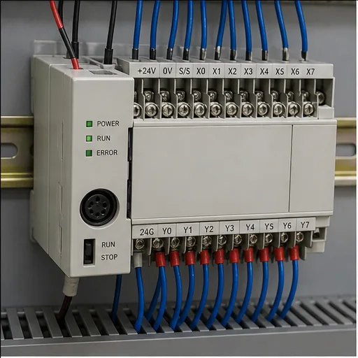
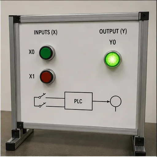
Separate physical I/O, internal Boolean state, numeric data, timer/counter state and special/system areas within X and Y I/O, M internal relays, D registers, T timers and C counters.
Program scan
Follow the same input-read, logic-execution and output-update reasoning while confirming platform-specific task and refresh details.
Symbolic naming
Use meaningful symbols and comments even when maintenance requires device addresses to remain visible.
Retentive state
Confirm which areas and instructions retain state through mode change or power cycle for the exact CPU configuration.
Online observation
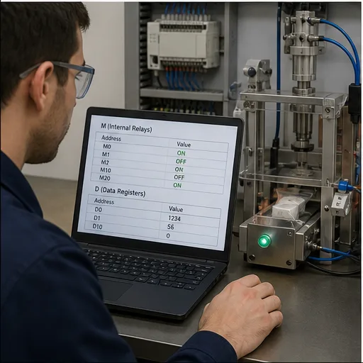
Monitor device state to compare input, logic result, output command and feedback without treating a forced value as normal operation.
Transfer boundary
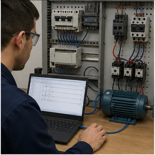
Use WPLSoft or ISPSoft conventions depend on the selected Delta family; repeat syntax, compile, download, timing and I/O tests before real deployment.
- 01
Choose the CPU context
Record controller family, software and firmware assumptions.
Evidence: The exercise has a target boundary.
Avoid: Writing “all models” instructions.
- 02
Map the devices
Assign the example using X and Y I/O, M internal relays, D registers, T timers and C counters.
Evidence: Every address has one engineering role.
Avoid: Reusing a device for unrelated state.
- 03
Write normal behavior
Build one start/stop or sequence requirement.
Evidence: The program is readable and observable.
Avoid: Translating mnemonics without intent.
- 04
Monitor scans
Toggle inputs and watch devices, timers and outputs.
Evidence: State matches the predicted table.
Avoid: Using force as permanent logic.
- 05
Test reset and restart
Exercise stop, fault, mode change and initialization.
Evidence: Retained and cleared state is explicit.
Avoid: Assuming simulator persistence matches CPU memory.
- 06
Verify officially
Open the equivalent project in the supported vendor tool and hardware path.
Evidence: Compile and runtime evidence is target-specific.
Avoid: Treating browser success as commissioning.
| Observed symptom | Inspect | Interpretation | Next proving action |
|---|---|---|---|
| Input address never changes | Physical mapping, channel/device address, refresh and force state | The program may read a different device than the wired point. | Verify the hardware map. |
| Internal bit changes unexpectedly | Every writer, special-area overlap and initialization | Memory ownership is unclear. | Cross-reference writes. |
| Timer behavior differs | Time base, instance/device, retentive semantics and task timing | Similar mnemonics can have platform differences. | Use the exact instruction help. |
| Value is corrupt | Register width, signedness, word order and conversion | The same device words can represent different types. | Inspect typed interpretation. |
| Download/run differs | CPU mode, compile warnings, retained values and I/O refresh | Editor simulation did not reproduce controller state. | Repeat on a controlled target. |
| Fault returns after reset | Active cause, diagnostic buffer and reset permissives | Reset is not removal of cause. | Read the official diagnostic record. |
Product evidence / 05
What the browser practice can actually demonstrate
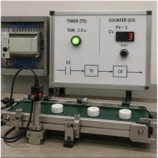
The browser dialect page provides parser-tested examples, mapped memory concepts, runnable scenarios and an explicit boundary: WPLSoft or ISPSoft conventions depend on the selected Delta family.
Can I learn this PLC family online?
Yes. Learn X and Y I/O, M internal relays, D registers, T timers and C counters, common instructions and monitoring concepts online, then use official software and hardware for platform competence.
Is this the official vendor simulator?
No. It is WPLSoft or ISPSoft conventions depend on the selected Delta family.
Do device addresses work the same on every model?
No. CPU families, modules and software generations vary. Confirm the exact manuals.
Can I import this project into vendor software?
Do not assume project-file compatibility. Recreate and verify the example in the official environment.
Which program should I build first?
Use a start-stop circuit with stop priority, then a timer or counter scenario with explicit reset.
Why are symbols still important?
Symbols preserve engineering meaning while device addresses satisfy the platform mapping.
Can a browser test prove real I/O?
No. It proves the learning runtime behavior; physical I/O and task behavior need target tests.
Does the vendor endorse this page?
No. Vendor names and trademarks identify independent educational context.