Motion and state
Its rotary state can be driven from a PLC output so speed and direction remain visible during a scan.
operator controls · rotary model
A PLC potentiometer provides an adjustable analog setpoint by dividing a stable reference voltage. The wiper voltage changes with knob position and enters a PLC analog channel, where raw counts are scaled into engineering units. The program should clamp the result, detect implausible values and apply only enough filtering or deadband to make the command stable.
Create a free account to run this scenario, or try a PLC lab now — no signup.
Explore Potentiometer in 3D
Load the interactive model when you are ready to rotate, inspect and operate it. Deferring WebGL keeps the reference page fast.
Its rotary state can be driven from a PLC output so speed and direction remain visible during a scan.
Commission it by proving setpoint before accepting the next sequence state.
Inject stuck-on, stuck-off states and require the PLC sequence to detect, stop and recover deliberately.
PLC integration guide
Connect the two end terminals across the approved reference and common, with the wiper feeding the voltage input. Confirm the analog module input range and common arrangement before energising. A potentiometer is not a universal current-loop source. Cable shielding, separation from motor conductors and a clean reference reduce noise; a broken wiper can otherwise leave the input floating at an unpredictable value.
Use the module raw minimum and maximum—not assumed generic values—to convert the input into percent, speed, pressure or another bounded unit. Clamp outside the intended range and show both raw and scaled values during commissioning. Decide whether zero volts means a valid zero command or a wiring fault; adding end resistors or a restricted valid band can make open or short circuits easier to distinguish.
Small raw fluctuations can make an HMI value or speed command hunt. A modest low-pass filter or deadband can stabilise the setpoint, but excessive filtering creates lag after the operator turns the knob. Keep safety limits and equipment constraints downstream of the operator request so no potentiometer position can demand an invalid operating condition.
The reference above focuses on PLC integration. The interactive school lesson shows the device, signal or mechanism before you write the control sequence.
Learn how analog signals become PLC valuesSignal map
PLC input Setpoint (%)
| Signal | PLC direction | Type / range |
|---|---|---|
| Setpoint value | input | float · % · 0–100 |
Field checklist
Fault finding
| Symptom | Check |
|---|---|
| Value jumps while turning | Inspect a worn wiper, loose terminal, noisy reference, grounding, shielding and raw-count filtering. |
| Only part of the range is available | Check end-terminal voltage, input range configuration and the raw scaling endpoints. |
| Value rises when the knob is turned down | Swap the end terminals or reverse the scaling consistently; do not hide an undocumented wiring convention. |
Fault and recovery exercise
Inject stuck-on, stuck-off states and require the PLC sequence to detect, stop and recover deliberately.
The model teaches PLC sequence behaviour and diagnosis. Confirm ratings, wiring, guarding, process calculations and commissioning limits against the real manufacturer documentation and site design.
Plain-English answers
Not as a plain voltage divider. Use the correct voltage input or an appropriate signal-conditioning circuit designed for the current-loop channel.
Use the range recommended for the analog source and module so loading, current and noise remain acceptable. Common values are not a substitute for the module manual.
A restricted valid voltage range, bias network or dedicated diagnostics can make open-wire values identifiable. The exact method depends on the input hardware and risk.
Free first success
Open a related browser scenario, run the PLC logic and see the component state respond. Start without installing software or entering a card.
Keep building
operator controls
Its travel is animated along the validated local axis and can expose command and end-state feedback.
operator controls
Its visible state changes with simulated I/O, making status and diagnosis readable in the scene.
operator controls
Its visible state changes with simulated I/O, making status and diagnosis readable in the scene.
Technical reference and worked-example guide
Direct answer
The reader can define excitation, wiper range, reference, input impedance and scaling, then diagnose open, noisy, reversed and end-stop behavior.
Written for pLC, electronics and instrumentation learners connecting a resistive potentiometer to a compatible voltage-measurement circuit and scaled engineering tag.
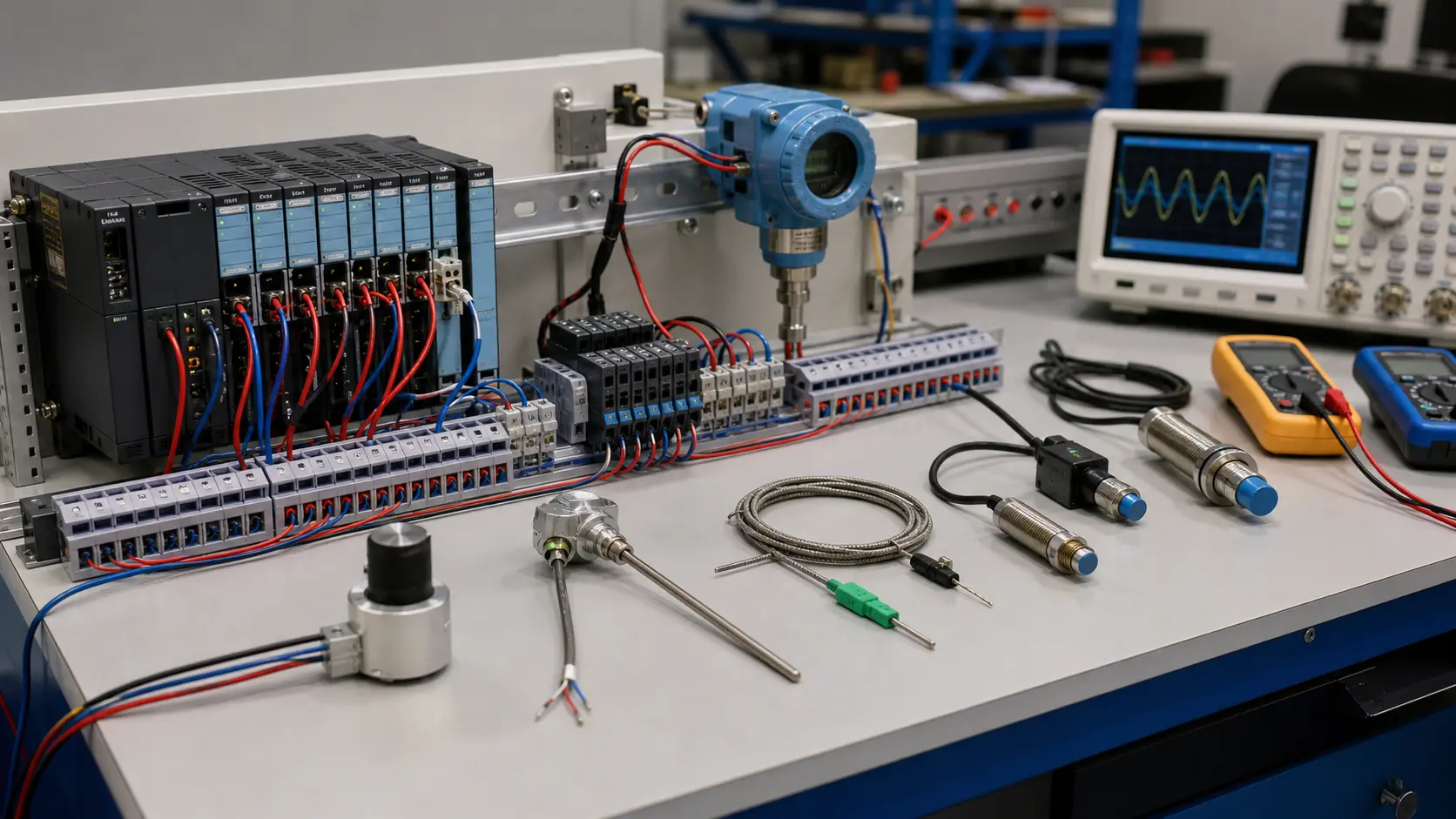
Resistance, taper, travel, supply, wiper range, reference, loading, PLC input range, resolution, units, mechanical coupling and failure state.
Shaft or slider position through resistance divider, wiper voltage, common reference, analog channel, raw count, scaling and independent position check.
Minimum, midpoint and maximum positions producing stable raw and engineering values within declared tolerance.
Open wiper, open end, reversed ends, intermittent track, noise, overtravel, ground offset, input overload and power return.
A mechanical, excitation, divider, reference, wiring, input-mode, loading, scaling or interpretation mismatch.
The selected device measured across actual travel and verified with the target analog-input documentation.
Only when the excitation, output range, reference and input characteristics are compatible; many installations need appropriate signal conditioning or isolation.
A worn or dirty track, loose wiper, vibration, noisy supply, poor reference, cable interference or insufficient filtering can make the signal unstable.