Industrial hardware field guide
Industrial automation components: recognize, connect and diagnose
Direct answer
Industrial automation components form a chain: an operator or sensor provides information, the PLC decides, an interface and protection layer handles the load, an actuator changes the machine, and feedback proves the result. Learn each device by its job, terminals, normal state and failure evidence.
This guide is written for pLC programmers who need hardware literacy, maintenance learners identifying panel devices and technicians tracing how field energy follows a controller command. The intended result is specific: the learner can identify contactors, overloads, relays, VFDs, emergency-stop devices, solenoid valves and cylinders, then explain where each sits between PLC output and machine response.
System map / 02
Six concepts that control the result
Treat these as connected checkpoints. Each checkpoint has an expected state, an observable state and a boundary to the next part of the system. That structure prevents a software indication from being mistaken for physical proof.
Control device
Pushbuttons, selectors, relays and PLC outputs carry decisions and low-power control state rather than the main energy required by large loads.
Switching interface
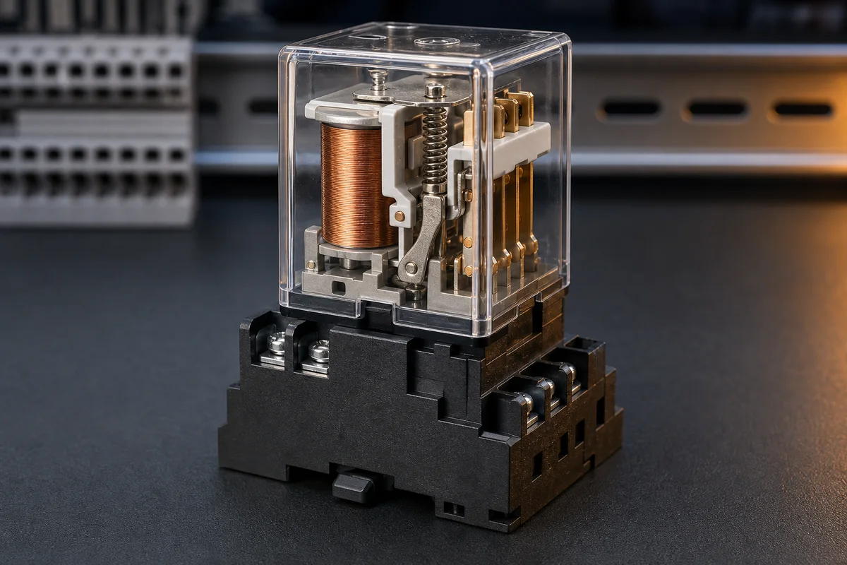
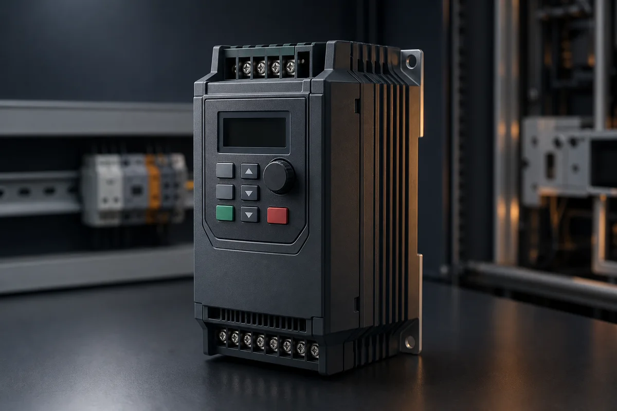
A relay, contactor, solid-state device or drive converts a controller command into an electrically suitable path for the controlled equipment.
Protection
Fuses, breakers, overloads and protective functions address different fault or thermal conditions and must be selected as a coordinated system.
Actuator
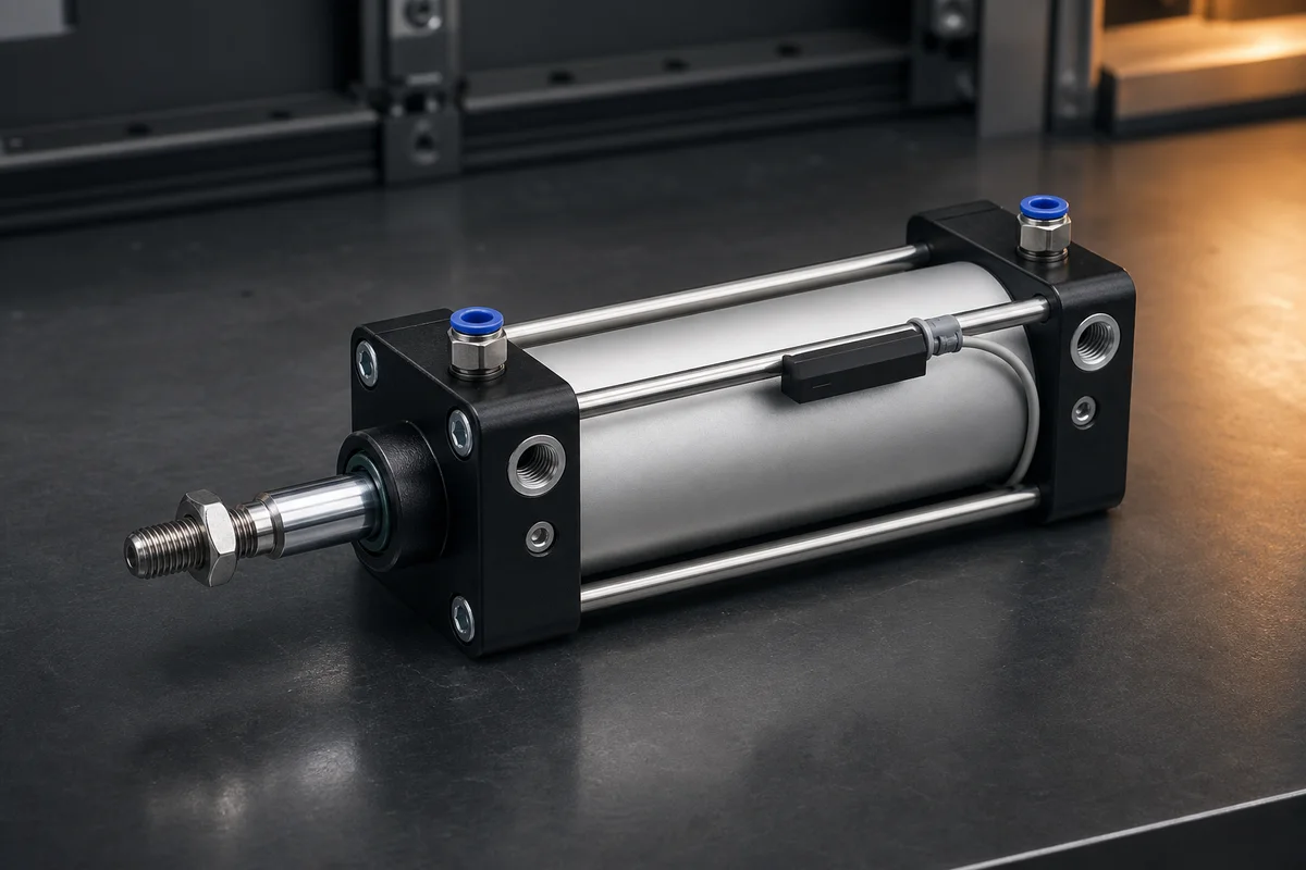
Motors, valves and cylinders turn electrical control into rotation, flow, pressure or linear motion with measurable physical limits.
Feedback
Auxiliary contacts, end switches, encoders and process sensors provide independent evidence that the requested physical change occurred.
Safe state
Emergency and protective functions depend on architecture, failure modes and validation—not on one component label or a standard PLC bit.
Procedure / 03
A six-step practice and commissioning workflow
Run the steps in order the first time. Later, the same structure becomes a diagnostic loop: define the expected condition, observe the boundary, interpret the difference and choose one proving action.
- 01
Name the job
Describe what must be switched, protected, moved or measured.
Evidence: The functional requirement narrows the component family.
Avoid: Choosing a part from appearance alone.
- 02
Read the markings
Identify designation, ratings, coil or supply, terminals and standards shown on the actual device.
Evidence: The device identity can be matched to its datasheet.
Avoid: Assuming similar enclosures have identical internals.
- 03
Trace terminals
Map line/load, coil, common, normally open/closed, signal and protective terminals.
Evidence: The physical map agrees with the schematic symbol and wire references.
Avoid: Using wire color instead of terminal function.
- 04
Predict normal state
State contact, output and feedback condition when de-energized and energized.
Evidence: Expected readings are known before operation.
Avoid: Calling normally open a command behavior rather than physical normal state.
- 05
Operate in context
Command the component inside a motor, pneumatic or PLC signal path.
Evidence: Upstream command and downstream response change coherently.
Avoid: Testing the device without its load or feedback contract.
- 06
Diagnose one failure
Compare command, component state, energy path and feedback.
Evidence: The first disagreement identifies a useful proving test.
Avoid: Replacing the device because it is the most visible part.
Diagnostic matrix / 04
Symptoms, proving points and next actions
The table is a reasoning aid, not a parts-replacement chart. Preserve the initial symptom, inspect the named boundary and use the interpretation to choose the next controlled test. Site safety procedures and equipment manuals remain authoritative.
| Observed symptom | Inspect | Interpretation | Next proving action |
|---|---|---|---|
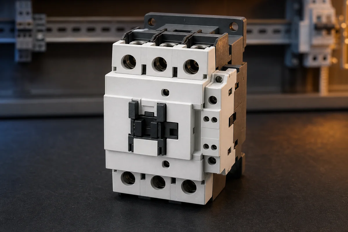
| Contactor chatters | Coil voltage, control-chain stability, mechanical condition and rating | Unstable coil energy or mechanism can repeatedly open the power path. | Trend coil command and measure the supply under load. |
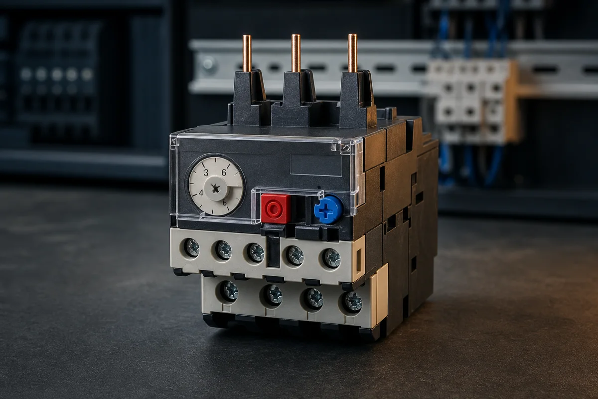
| Overload trips | Motor current, phase balance, load, setting, cooling and starting duty | The overload may be correctly responding to excessive thermal demand. | Correct the cause before reset or setting change. |
| Relay output is commanded but open | Coil state, contact assignment, contact wear and terminal wiring | The PLC command can be correct while the interface contact fails. | Prove coil and contact as separate boundaries. |
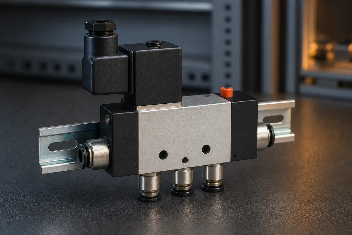
| Solenoid clicks, cylinder does not move | Air supply, valve spool, flow controls, tubing, cylinder load and end state | Electrical actuation does not guarantee pneumatic flow or mechanical motion. | Compare pressure and valve/cylinder state. |
| VFD ready but motor stopped | Run source, reference source, STO, limits, interlocks and output state | Ready indicates one state, not a complete valid run contract. | Prove command and reference ownership. |
| Feedback disagrees | Auxiliary contact, sensor mounting, wiring, tag mapping and physical state | Independent feedback may expose a failed actuator or failed feedback device. | Use another observation to distinguish them. |
Product evidence / 05
What the browser practice can actually demonstrate
Component School combines recognition-grade visuals, cutaway motion, terminal labels, stateful controls, failure modes and links into operating motor, wiring, pneumatic and drive labs.
Where simulation stops
Recognition training is not equipment selection or safety validation. Ratings, coordination, wiring, guarding and application suitability must come from the exact manufacturer documentation and applicable engineering process.
Commissioning notebook / 06
Six cases that turn the concepts into evidence
Use these as written briefs rather than click-through instructions. For every case, state the expected condition before acting, retain the first useful observation and explain why the final result proves the requirement. A different program or component choice can still be correct when it produces the same bounded behavior and evidence.
Case 01
predict → observe → prove
Prove control device
Engineering context. Pushbuttons, selectors, relays and PLC outputs carry decisions and low-power control state rather than the main energy required by large loads. Begin with a written normal condition and identify which request, state, physical result or communication value will provide independent confirmation. Do not begin by changing the configuration; the initial state is part of the evidence and should remain reproducible.
Controlled setup. Use the “Name the job” stage of the workflow: describe what must be switched, protected, moved or measured. The acceptance record should show this result: the functional requirement narrows the component family. Record initial conditions, the exact stimulus and the observation point so another learner can repeat the case without relying on your memory.
Fault challenge. Introduce or analyse “Contactor chatters” as one bounded deviation. Inspect coil voltage, control-chain stability, mechanical condition and rating The working interpretation is that unstable coil energy or mechanism can repeatedly open the power path. The next proving action is to trend coil command and measure the supply under load. Change only one condition before observing the result, and preserve timestamps or measurements where timing matters.
Review and recovery. The most common trap here is choosing a part from appearance alone. After restoring the cause, repeat the normal case and at least one stop, timeout, disconnect or restart boundary relevant to this topic. Remove temporary forces and bypasses, return the model to a known state and retain the evidence that both operation and recovery are deliberate.
Explain it aloud: What components are found in a PLC control panel? A defensible short answer is: Typical panels contain isolation and protection, power supplies, PLC and I/O, terminal blocks, relays or contactors, drives, networking and operator or safety interfaces.
Case 02
predict → observe → prove
Prove switching interface
Engineering context. A relay, contactor, solid-state device or drive converts a controller command into an electrically suitable path for the controlled equipment. Begin with a written normal condition and identify which request, state, physical result or communication value will provide independent confirmation. Do not begin by changing the configuration; the initial state is part of the evidence and should remain reproducible.
Controlled setup. Use the “Read the markings” stage of the workflow: identify designation, ratings, coil or supply, terminals and standards shown on the actual device. The acceptance record should show this result: the device identity can be matched to its datasheet. Record initial conditions, the exact stimulus and the observation point so another learner can repeat the case without relying on your memory.
Fault challenge. Introduce or analyse “Overload trips” as one bounded deviation. Inspect motor current, phase balance, load, setting, cooling and starting duty The working interpretation is that the overload may be correctly responding to excessive thermal demand. The next proving action is to correct the cause before reset or setting change. Change only one condition before observing the result, and preserve timestamps or measurements where timing matters.
Review and recovery. The most common trap here is assuming similar enclosures have identical internals. After restoring the cause, repeat the normal case and at least one stop, timeout, disconnect or restart boundary relevant to this topic. Remove temporary forces and bypasses, return the model to a known state and retain the evidence that both operation and recovery are deliberate.
Explain it aloud: What is the difference between a relay and contactor? A defensible short answer is: Both use a control input to change contacts, but contactors are generally designed for higher-power load switching and include features suited to repeated motor or power duty.
Case 03
predict → observe → prove
Prove protection
Engineering context. Fuses, breakers, overloads and protective functions address different fault or thermal conditions and must be selected as a coordinated system. Begin with a written normal condition and identify which request, state, physical result or communication value will provide independent confirmation. Do not begin by changing the configuration; the initial state is part of the evidence and should remain reproducible.
Controlled setup. Use the “Trace terminals” stage of the workflow: map line/load, coil, common, normally open/closed, signal and protective terminals. The acceptance record should show this result: the physical map agrees with the schematic symbol and wire references. Record initial conditions, the exact stimulus and the observation point so another learner can repeat the case without relying on your memory.
Fault challenge. Introduce or analyse “Relay output is commanded but open” as one bounded deviation. Inspect coil state, contact assignment, contact wear and terminal wiring The working interpretation is that the PLC command can be correct while the interface contact fails. The next proving action is to prove coil and contact as separate boundaries. Change only one condition before observing the result, and preserve timestamps or measurements where timing matters.
Review and recovery. The most common trap here is using wire color instead of terminal function. After restoring the cause, repeat the normal case and at least one stop, timeout, disconnect or restart boundary relevant to this topic. Remove temporary forces and bypasses, return the model to a known state and retain the evidence that both operation and recovery are deliberate.
Explain it aloud: Does a PLC power a motor directly? A defensible short answer is: Usually no. The PLC commands a contactor, starter or drive, while the power circuit supplies and protects the motor.
Case 04
predict → observe → prove
Prove actuator
Engineering context. Motors, valves and cylinders turn electrical control into rotation, flow, pressure or linear motion with measurable physical limits. Begin with a written normal condition and identify which request, state, physical result or communication value will provide independent confirmation. Do not begin by changing the configuration; the initial state is part of the evidence and should remain reproducible.
Controlled setup. Use the “Predict normal state” stage of the workflow: state contact, output and feedback condition when de-energized and energized. The acceptance record should show this result: expected readings are known before operation. Record initial conditions, the exact stimulus and the observation point so another learner can repeat the case without relying on your memory.
Fault challenge. Introduce or analyse “Solenoid clicks, cylinder does not move” as one bounded deviation. Inspect air supply, valve spool, flow controls, tubing, cylinder load and end state The working interpretation is that electrical actuation does not guarantee pneumatic flow or mechanical motion. The next proving action is to compare pressure and valve/cylinder state. Change only one condition before observing the result, and preserve timestamps or measurements where timing matters.
Review and recovery. The most common trap here is calling normally open a command behavior rather than physical normal state. After restoring the cause, repeat the normal case and at least one stop, timeout, disconnect or restart boundary relevant to this topic. Remove temporary forces and bypasses, return the model to a known state and retain the evidence that both operation and recovery are deliberate.
Explain it aloud: What does an overload relay protect? A defensible short answer is: It responds to sustained motor overcurrent or modeled thermal demand. It is not the same as short-circuit protection and does not replace coordinated protective design.
Case 05
predict → observe → prove
Prove feedback
Engineering context. Auxiliary contacts, end switches, encoders and process sensors provide independent evidence that the requested physical change occurred. Begin with a written normal condition and identify which request, state, physical result or communication value will provide independent confirmation. Do not begin by changing the configuration; the initial state is part of the evidence and should remain reproducible.
Controlled setup. Use the “Operate in context” stage of the workflow: command the component inside a motor, pneumatic or PLC signal path. The acceptance record should show this result: upstream command and downstream response change coherently. Record initial conditions, the exact stimulus and the observation point so another learner can repeat the case without relying on your memory.
Fault challenge. Introduce or analyse “VFD ready but motor stopped” as one bounded deviation. Inspect run source, reference source, STO, limits, interlocks and output state The working interpretation is that ready indicates one state, not a complete valid run contract. The next proving action is to prove command and reference ownership. Change only one condition before observing the result, and preserve timestamps or measurements where timing matters.
Review and recovery. The most common trap here is testing the device without its load or feedback contract. After restoring the cause, repeat the normal case and at least one stop, timeout, disconnect or restart boundary relevant to this topic. Remove temporary forces and bypasses, return the model to a known state and retain the evidence that both operation and recovery are deliberate.
Explain it aloud: Why use an interposing relay? A defensible short answer is: It can provide isolation, contact multiplication or an interface between different electrical requirements. Ratings and failure behavior still need engineering review.
Case 06
predict → observe → prove
Prove safe state
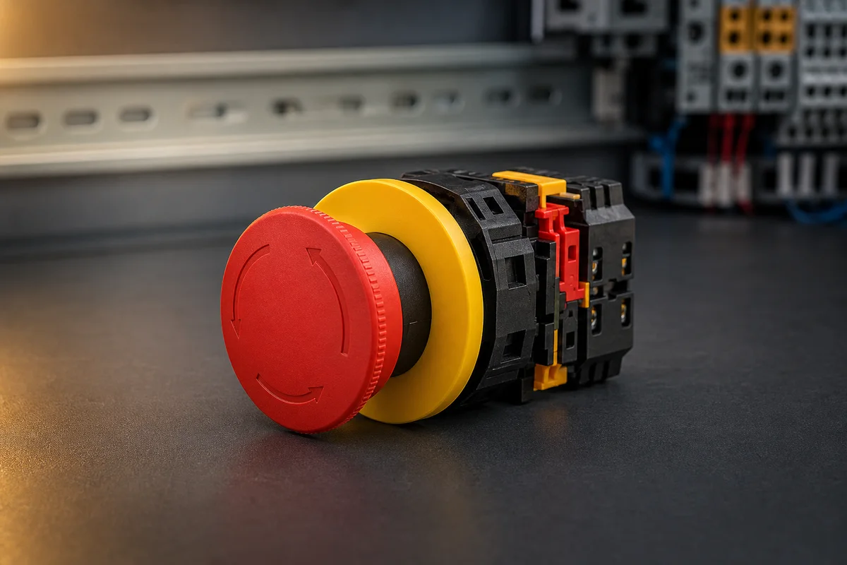
Engineering context. Emergency and protective functions depend on architecture, failure modes and validation—not on one component label or a standard PLC bit. Begin with a written normal condition and identify which request, state, physical result or communication value will provide independent confirmation. Do not begin by changing the configuration; the initial state is part of the evidence and should remain reproducible.
Controlled setup. Use the “Diagnose one failure” stage of the workflow: compare command, component state, energy path and feedback. The acceptance record should show this result: the first disagreement identifies a useful proving test. Record initial conditions, the exact stimulus and the observation point so another learner can repeat the case without relying on your memory.
Fault challenge. Introduce or analyse “Feedback disagrees” as one bounded deviation. Inspect auxiliary contact, sensor mounting, wiring, tag mapping and physical state The working interpretation is that independent feedback may expose a failed actuator or failed feedback device. The next proving action is to use another observation to distinguish them. Change only one condition before observing the result, and preserve timestamps or measurements where timing matters.
Review and recovery. The most common trap here is replacing the device because it is the most visible part. After restoring the cause, repeat the normal case and at least one stop, timeout, disconnect or restart boundary relevant to this topic. Remove temporary forces and bypasses, return the model to a known state and retain the evidence that both operation and recovery are deliberate.
Explain it aloud: How does a solenoid valve work with a PLC? A defensible short answer is: A PLC output energizes a suitable valve coil or interface; the spool changes air or fluid paths; cylinder or process feedback confirms physical response.
Answer surface / 07
Questions people ask about Industrial automation components
These concise answers define the operating, training and product boundaries most often missed in broad summaries. The full workflow and diagnostic table above provide the evidence behind them.
What components are found in a PLC control panel?
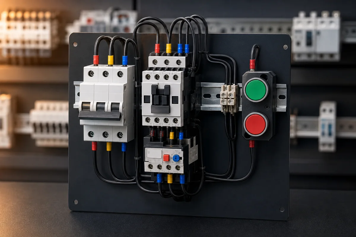
Typical panels contain isolation and protection, power supplies, PLC and I/O, terminal blocks, relays or contactors, drives, networking and operator or safety interfaces.
What is the difference between a relay and contactor?
Both use a control input to change contacts, but contactors are generally designed for higher-power load switching and include features suited to repeated motor or power duty.
Does a PLC power a motor directly?
Usually no. The PLC commands a contactor, starter or drive, while the power circuit supplies and protects the motor.
What does an overload relay protect?
It responds to sustained motor overcurrent or modeled thermal demand. It is not the same as short-circuit protection and does not replace coordinated protective design.
Why use an interposing relay?
It can provide isolation, contact multiplication or an interface between different electrical requirements. Ratings and failure behavior still need engineering review.
How does a solenoid valve work with a PLC?
A PLC output energizes a suitable valve coil or interface; the spool changes air or fluid paths; cylinder or process feedback confirms physical response.
What is a normally closed contact?
It is closed in the defined normal, de-energized and unactuated condition. Always confirm the device convention and schematic context.
Can a component simulator replace a datasheet?
No. It teaches function and diagnosis; exact ratings, terminals, environmental limits and approvals come from the installed model documentation.
Continue the signal path / 08