A bottle filling PLC program is the gateway to production-line coordination: a photo-eye detects the bottle, the conveyor stops, a timed fill valve opens, and a counter records each completed bottle. Below is the full ladder diagram for a bottle filling plant, the I/O table, the fill timing sequence and a counter rung — all grounded in the live three-station bottling-line scenario you can write and run in your browser without installing anything.
coordinationlinestate-machinepro
Ready to build this?
Sign up free — no credit card required. This scenario requires the Pro plan.
A three-station bottling line: bottles travel left-to-right on a fixed-speed conveyor through a FILL head, a CAP press, and a LABEL applicator. Photo-eyes (PE_STATION_1/2/3) detect a bottle at each station; fill/cap/label DONE signals from the station instrumentation tell you the current bottle is finished. Your controller starts the line on START, stops it on STOP or when the REJECT_FULL sensor tells you the reject bin needs emptying, and runs each actuator only while a bottle is in its station and not yet done. A JAM input from the line's supervisory sensor latches a fault that stops the conveyor and sounds ALARM_HORN until operator intervention. The status lamps READY/RUN/FAULT must accurately reflect which mode the line is in.
Objectives
Latch RUN on START, clear it on STOP, REJECT_FULL, or latched JAM_FAULT
Energize FILL_HEAD only while PE_STATION_1 is made, FILL_DONE is not yet true, and the line is running
Energize CAP_PRESS only while PE_STATION_2 is made, CAP_DONE is not yet true, and the line is running
Energize LABEL_DRIVE only while PE_STATION_3 is made, LABEL_DONE is not yet true, and the line is running
Run CONVEYOR while RUN is latched AND NOT REJECT_FULL AND NOT JAM_FAULT
Latch JAM_FAULT on any JAM input rising edge; ALARM_HORN := JAM_FAULT OR (REJECT_FULL AND RUN)
Status lamps: READY := /RUN AND /JAM_FAULT; STATUS_LAMP_RUN := CONVEYOR; STATUS_LAMP_FAULT := JAM_FAULT
Interlock: no station actuator may energise while its photo-eye is low (prevents dry-firing a fill head with no bottle present)
Hints
Use a SET/RESET pair for RUN: `| START | S= RUN ;` and `| STOP OR JAM_FAULT | R= RUN ;`
JAM_FAULT latch: `| JAM | S= JAM_FAULT ;` — there is no auto-reset; the operator must cycle power (or the scenario is reset).
The three station rungs all follow the same shape: `| PE_N AND /DONE_N AND RUN AND /JAM_FAULT | := ACTUATOR_N ;`
CONVEYOR rung: `| RUN AND /REJECT_FULL AND /JAM_FAULT | := CONVEYOR ;` — the physics pauses the bottle at an actuating station automatically, so the ladder does NOT need to stop the conveyor while a station works.
ALARM_HORN := JAM_FAULT OR (REJECT_FULL AND RUN). STATUS_LAMP_READY := /RUN AND /JAM_FAULT. STATUS_LAMP_RUN := CONVEYOR. STATUS_LAMP_FAULT := JAM_FAULT.
I/O Table
Inputs
START
Operator start push-button
BOOL · %I0.0
STOP
Operator emergency-stop push-button
BOOL · %I0.1
REJECT_FULL
Reject-tray-full prox switch
BOOL · %I0.2
PE_STATION_1
Photo-eye at fill station
BOOL · %I1.0
PE_STATION_2
Photo-eye at cap station
BOOL · %I1.1
PE_STATION_3
Photo-eye at label station
BOOL · %I1.2
FILL_DONE
Fill-complete signal (level reached)
BOOL · %I1.3
CAP_DONE
Cap-placed signal
BOOL · %I1.4
LABEL_DONE
Label-applied signal
BOOL · %I1.5
JAM
Line-jam supervisory sensor
BOOL · %I1.6
Outputs
CONVEYOR
Main conveyor motor contactor
BOOL · %Q0.0
FILL_HEAD
Fill-head actuator solenoid
BOOL · %Q0.1
CAP_PRESS
Cap-press actuator solenoid
BOOL · %Q0.2
LABEL_DRIVE
Label applicator motor
BOOL · %Q0.3
ALARM_HORN
Audible alarm on jam / reject-full
BOOL · %Q0.5
STATUS_LAMP_READY
Ready-to-run indicator lamp
BOOL · %Q0.6
STATUS_LAMP_RUN
Line-running indicator lamp
BOOL · %Q0.7
STATUS_LAMP_FAULT
Fault / jam indicator lamp
BOOL · %Q1.0
Your program will be tested against:
All test cases run automatically when you submit. Assertions are hidden until you pass.
#1One bottle completes fill → cap → label and exits the line
Press START. Conveyor runs. The first spawned bottle reaches PE_STATION_1 — FILL_HEAD fires and physics marks it filled after ~1 s. The bottle advances to PE_STATION_2, CAP_PRESS fires, then PE_STATION_3 with LABEL_DRIVE. Finally the bottle exits and throughputCount increments to 1.
#2STOP drops conveyor and all station actuators within 200 ms
Start the line, wait for the first bottle to reach PE_STATION_1 (and FILL_HEAD to fire). Press STOP. Within 200 ms CONVEYOR, FILL_HEAD, CAP_PRESS, and LABEL_DRIVE must all be off.
#3REJECT_FULL stops the conveyor and sounds the alarm
While the line is running, set REJECT_FULL true. CONVEYOR must drop and ALARM_HORN must rise. Clear REJECT_FULL and confirm CONVEYOR returns.
#4A JAM signal latches JAM_FAULT, drops CONVEYOR, and fires ALARM_HORN
Run the line, then inject JAM = true for a single scan. JAM_FAULT must latch via the ladder SET, CONVEYOR must drop, STATUS_LAMP_FAULT must rise, and ALARM_HORN must be on. The latch survives the JAM input clearing.
#5Station actuators stay off when no bottle is present at the station
Immediately after START, before any bottle has reached a station, all three PE inputs are low — FILL_HEAD, CAP_PRESS, and LABEL_DRIVE must all be off. This guards against dry-firing.
I/O assignment for a bottle filling PLC program
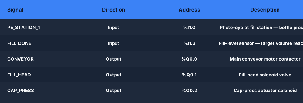
Before writing a single rung you need to assign every field device to a PLC address. A minimal bottle filling system has two inputs — a bottle-present photo-eye (PE_STATION_1) and a fill-level sensor (FILL_DONE) that confirms the target volume has been reached — and two outputs: the conveyor motor contactor (CONVEYOR) and the fill-valve solenoid (FILL_HEAD).
In the full three-station bottling-line scenario the I/O grows to ten inputs and nine outputs covering fill, cap and label stations, a reject-full prox switch, a jam sensor, an alarm horn and three status lamps. The table below shows the core bottle filling I/O; the live scenario includes all the additional signals you need for a production-grade program.
Core bottle filling I/O: PE_STATION_1 and FILL_DONE as inputs, CONVEYOR and FILL_HEAD as outputs.
PLC ladder diagram for bottle filling: the fill sequence rung
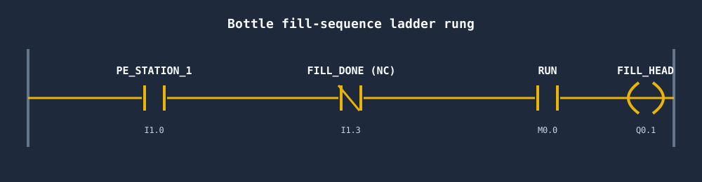
The heart of any plc ladder diagram for bottle filling system is the sequence that indexes a bottle into position and holds it while the fill valve is open. The conveyor runs whenever the line RUN bit is latched and no fault is active; when PE_STATION_1 detects a bottle the physics holds that bottle still while the FILL_HEAD coil is energised.
The fill-head rung follows a consistent shape that mirrors across every station in the line: PE_STATION (positive literal — no bottle means no fire), AND NOT FILL_DONE (prevent re-firing once the level is reached), AND RUN, AND NOT JAM_FAULT. When FILL_DONE goes true the coil drops and the conveyor resumes, carrying the bottle to the cap station.
The fill-sequence rung: bottle present AND fill not done AND line running energises the FILL_HEAD solenoid.
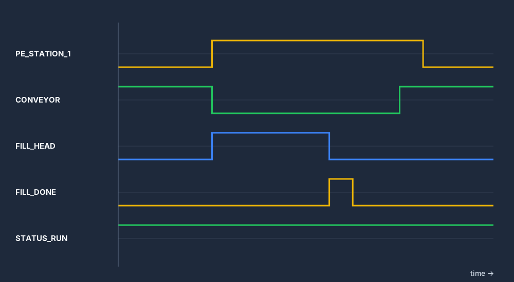
The timing diagram makes the fill cycle unmistakable. When PE_STATION_1 goes high (bottle detected) the physics halts the conveyor at that station, FILL_HEAD opens immediately, and it stays open until FILL_DONE goes high — the fill-level sensor confirming the target volume. The valve then closes and the conveyor resumes, carrying the bottle forward.
In a ladder diagram for bottle filling plant that uses a TON timer instead of a level sensor, FILL_HEAD is held open for the timer preset (e.g. T#5s) and the done bit closes the valve. The live scenario uses the level-sensor handshake method — the most robust approach for variable-density liquids — but the timing shape is identical whether you use a TON or a process sensor.
Fill timing: bottle detected → conveyor halts → fill valve open → FILL_DONE → valve closes → conveyor resumes.
Counting filled bottles with a CTU counter rung
Every production bottling line counts output. In ladder logic the CTU (count-up) instruction increments its accumulated value on a rising edge of its count input. The natural trigger is the FILL_DONE signal: each time a bottle successfully fills, FILL_DONE pulses high and the CTU accumulates one more count.
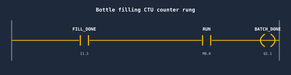
The counter rung shown below uses FILL_DONE as the count input and a high-count preset (e.g. 1 000) to drive a batch-complete output. In the live bottling-line scenario the physics tracks throughputCount internally and the test case asserts it equals 1 after the first bottle exits — so your counter logic is verified automatically when you run the scenario.
CTU counter rung: FILL_DONE rising edge increments the filled-bottle count; preset triggers a batch-complete output.
How to build a bottle filling PLC program step by step
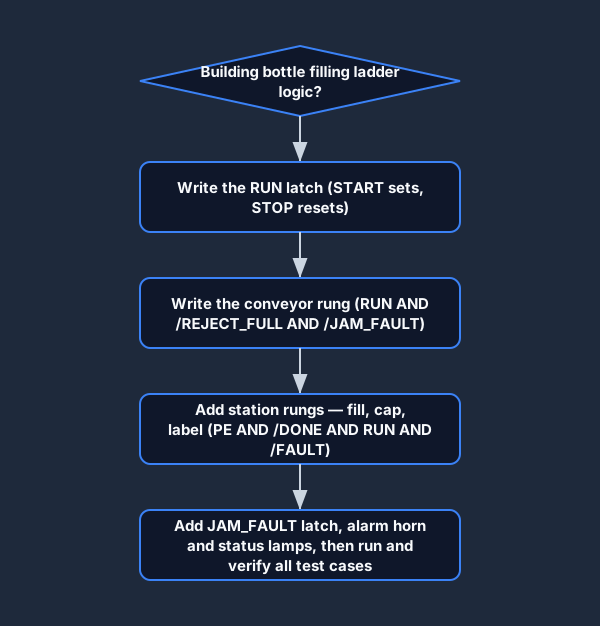
Writing a bottle filling PLC program for the first time is straightforward once you follow the correct build order. Start with the line-enable latch (START sets RUN, STOP resets it), then write the conveyor rung, then add each station rung in order — fill, cap, label. Add fault handling last so the interlocks are already in place when you test them.
The flowchart below shows this sequence. The live scenario enforces the same order through its test cases: the first test verifies a bottle completes all three stations, the second tests that STOP drops every actuator within 200 ms, and later tests check the jam latch and the reject-full interlock. Write your rungs in the order shown and you will pass all five tests without backtracking.
Build order: RUN latch → conveyor rung → station rungs (fill/cap/label) → fault/alarm → status lamps.
Automatic bottle filling system using PLC — the full ladder sequence
An automatic bottle filling system using a PLC ladder diagram strings the individual rungs above into one repeating, hands-off cycle. The conveyor indexes an empty bottle until PE_STATION_1 detects it, the physics halts that bottle, the FILL_HEAD solenoid opens, and the valve stays open until FILL_DONE confirms the target level — then the conveyor automatically resumes and carries the bottle to the cap and label stations while the next empty bottle indexes in behind it. No operator action is needed between bottles: the photo-eye is the trigger and the level sensor (or a TON timer, if you fill by time) is the release, so the line runs continuously until STOP drops the RUN latch.
This is what makes it a true bottle filling machine PLC program rather than a single manual fill — the sequencing, the fault interlocks (JAM_FAULT, REJECT_FULL) and the CTU production counter all run automatically every cycle. The whole sequence is runnable and auto-graded right here in your browser — and to keep a copy of this automatic bottle filling PLC ladder diagram (I/O table plus every rung) beside you while you build, press Ctrl/Cmd+P on this page and choose Save as PDF.
Frequently asked questions
What is the ladder diagram for a bottle filling plant?
The core is a photo-eye contact (PE_STATION_1) in series with a normally-closed FILL_DONE contact and the line RUN bit, driving a FILL_HEAD coil. When the bottle is present and the fill is not yet complete the valve opens; when FILL_DONE goes true the valve closes and the conveyor resumes. The full bottling-line ladder also includes cap and label station rungs, a JAM_FAULT latch, a reject-full interlock and status lamps.
What PLC instructions are used in a bottle filling PLC program?
The essential instructions are normally-open contacts (for PE and RUN), normally-closed contacts (for FILL_DONE and fault bits), output coils (for FILL_HEAD and CONVEYOR), a SET/RESET pair for the RUN latch, a SET-only latch for JAM_FAULT, and either a TON timer or a process-sensor handshake to control fill duration. A CTU counter on the FILL_DONE signal tracks production count.
How does a timed fill valve work in ladder logic?
A TON (on-delay timer) rung is enabled when the bottle-present photo-eye is true and the line is running. The timer preset equals the fill duration (e.g. T#5s for five seconds). While the timer is timing, the FILL_HEAD coil is energised through a contact on the timer timing bit (.TT). When the timer done bit (.DN) goes true, the coil drops and you can use the done bit to advance the sequence or reset the timer for the next cycle.
Can I run a bottle filling PLC program without hardware?
Yes. This page links to the live bottling-line scenario — write the ladder logic in your browser, press Run, and watch bottles travel through the fill, cap and label stations on a simulated conveyor. Five automated test cases grade your program including a full throughput test, a STOP interlock test, a reject-full test and a jam-latch test. No PLC, no install, no licence required.
How do I count bottles in a PLC ladder program?
Use a CTU (count-up) counter instruction with the FILL_DONE signal (or the label-done signal if you want to count fully processed bottles) as the count input. Each rising edge on the count input increments the accumulated value by one. Set the preset to your batch size — when the accumulator reaches the preset the counter done bit goes true, which you can use to trigger a batch-complete alarm or stop the line for a pallet change.
What is the difference between a level-sensor fill and a timed fill in PLC ladder logic?
A level-sensor fill uses a process sensor (ultrasonic, capacitive or pressure) to provide a FILL_DONE signal when the target volume is reached — the valve stays open exactly as long as needed regardless of flow rate variation. A timed fill uses a TON timer; the valve opens for a fixed preset every cycle. Level-sensor fills are more accurate for variable-density products; timed fills are simpler and common when flow rate is consistent. The live scenario uses the level-sensor handshake (FILL_DONE input) so your logic adapts to simulated fill times rather than a fixed timer.
What is the bottle filling PLC ladder logic in simple terms?
In plain terms: a contact for the bottle-present photo-eye (PE_STATION_1), in series with a normally-closed FILL_DONE contact and the line RUN bit, drives the FILL_HEAD valve coil. When a bottle is in position and not yet full, the valve opens; when the level sensor closes FILL_DONE, the valve drops and the conveyor moves the bottle on. That single rung is the whole bottle filling logic — the rest of the program just adds the conveyor, the production counter and the fault interlocks around it.
How do you make an automatic bottle filling system using a PLC ladder diagram?
Latch a RUN bit from START/STOP, drive the conveyor from RUN (blocked by JAM_FAULT and REJECT_FULL), and write a self-resetting fill rung: PE_STATION_1 AND NOT FILL_DONE AND RUN opens FILL_HEAD, and FILL_DONE both closes the valve and releases the conveyor. Because the photo-eye triggers each fill and the level sensor releases it, the cycle repeats automatically with no operator input. Add a CTU on FILL_DONE to count output and the line runs fully automatically until STOP.
What does a bottle filling machine PLC program need to handle?
A production-grade bottle filling machine PLC program needs the fill-sequence rung, a RUN/STOP latch, automatic conveyor indexing, a JAM_FAULT latch that stops the line on a jam sensor, a REJECT_FULL interlock so the line halts when the reject bin is full, a CTU production counter, and status lamps/alarm horn. The live three-station scenario on this page includes all of these and grades them with five automated test cases.
Watch the real browser product respond to the task on this page, then try the same practical workflow yourself. No slides, concept mockups, install, or credit card.