PLC Timers Explained: TON, TOF and TP
A PLC timer delays an action by a set amount of time. The three you will use every day are TON (on-delay), TOF (off-delay) and TP (pulse). They share the same four parameters — an enable input, a preset time, a done bit, and an elapsed-time value — and differ only in when the done bit turns on and off. Get those three behaviours straight and 90% of timing logic on a real machine becomes obvious.
This guide walks through each timer with a timing diagram, shows the ladder logic, and lists the names each vendor uses so you are not thrown when you switch from Allen-Bradley to Siemens.

The four parts of every timer
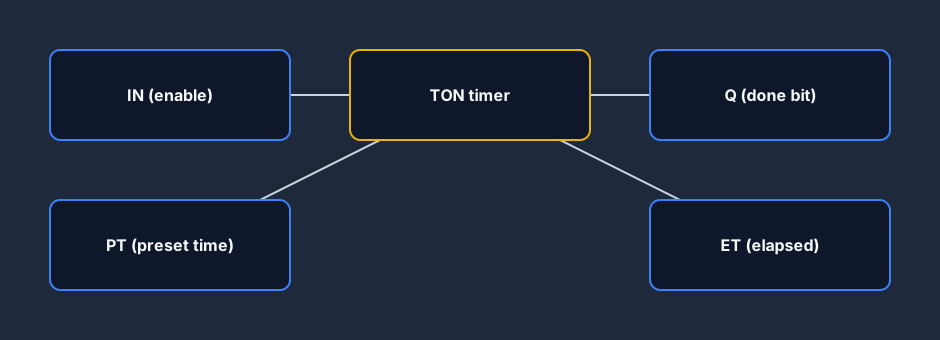
Every IEC 61131-3 timer is a function block with two inputs and two outputs:
- IN — the enable. While this is true the timer is allowed to run.
- PT — the preset time you are counting to (e.g.
T#5s). - Q — the done/output bit your logic actually reads.
- ET — the elapsed time so far, handy for HMIs and progress logic.
The single most common beginner bug is reading the enable (IN) in your logic when you meant to read the done bit (Q). Always drive downstream logic from Q.
TON — the on-delay timer
A TON waits. When IN goes true, ET starts counting up; once ET reaches PT, Q turns on. The moment IN goes false, Q drops and ET resets immediately.
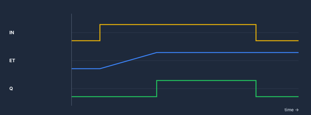
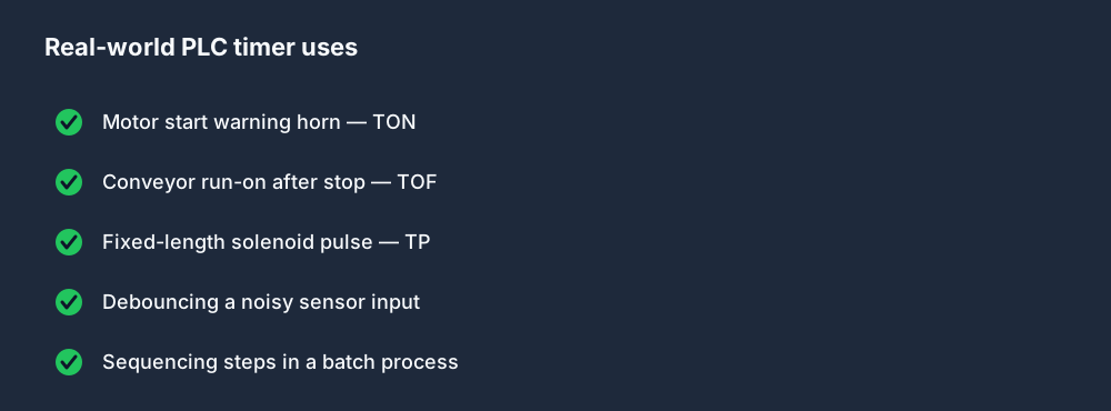
Use a TON whenever you want a delay before something happens — a warning horn that sounds for three seconds before a motor starts, or ignoring a sensor until a guard has been closed for half a second.
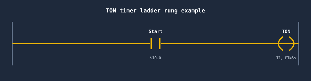
Here is the classic rung: a start contact enables the timer, and elsewhere you use the timer's Q bit to start the motor.
TOF — the off-delay timer
A TOF is the mirror image. Q turns on immediately when IN goes true. When IN goes false, Q stays on and ET counts up; only when ET reaches PT does Q finally turn off.
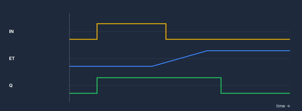
Reach for a TOF for "run-on" behaviour: keep a cooling fan running for two minutes after a machine stops, or hold a conveyor on briefly so the last part clears.
TP — the pulse timer
A TP fires a fixed-length pulse. On a rising edge of IN, Q turns on for exactly PT and then off — no matter whether IN stays true for a millisecond or an hour. A new pulse only starts on the next rising edge after the current one finishes.
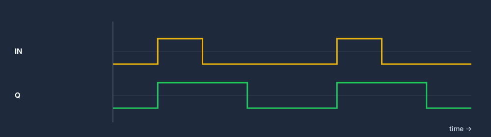
TP is perfect for a one-shot solenoid kick, a fixed-length glue dispense, or flashing a beacon at a steady rate.
TON vs TOF vs TP at a glance
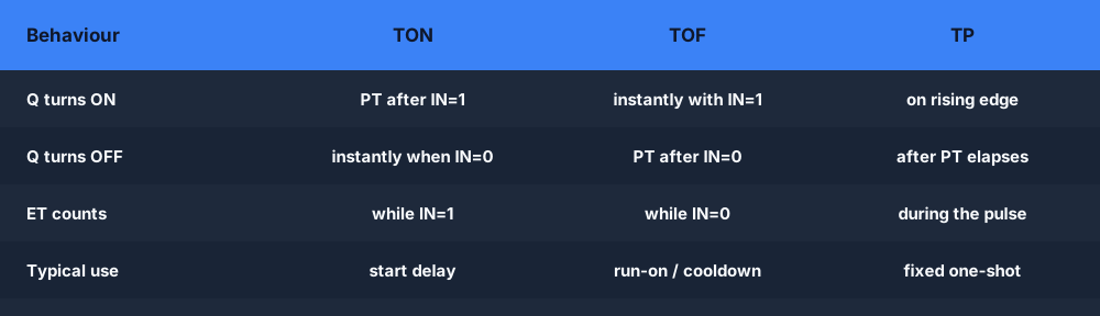
If you only remember one thing: TON delays ON, TOF delays OFF, TP makes a fixed pulse.
TON vs TOF — the key difference
TON (on-delay): Q turns on after the preset time once IN goes true. Q drops immediately when IN goes false.
TOF (off-delay): Q turns on immediately when IN goes true. Q stays on and keeps counting after IN goes false, dropping only when ET reaches PT.
| TON | TOF | TP | |
|---|---|---|---|
| When does Q turn ON? | PT seconds after IN goes true | Immediately when IN goes true | Immediately on rising edge of IN |
| When does Q turn OFF? | Immediately when IN goes false | PT seconds after IN goes false | After exactly PT, regardless of IN |
| ET resets when? | Immediately when IN goes false | Immediately when Q turns off | After the pulse completes |
| Typical use | Delay before starting something | Run-on after stopping something | Fixed-length pulse / one-shot |
| Allen-Bradley name | TON | TOF | — (use OSR for one-shots) |
| Siemens / IEC name | TON | TOF | TP |
The single most common mix-up: using a TON where you need a TOF. Ask yourself — do you want a delay before the output turns on (TON) or a delay before it turns off (TOF)?
Which timer should you use?
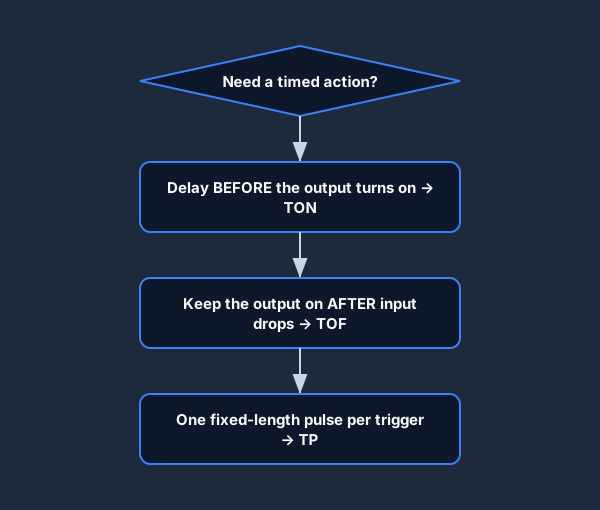
Ask what you need relative to the input: a delay before the output, a delay after it, or a pulse independent of it. That single question picks the timer almost every time.
Timer names in each PLC dialect
The behaviour is standard, but the names are not. If you learn the IEC 61131-3 names you can map everything else.
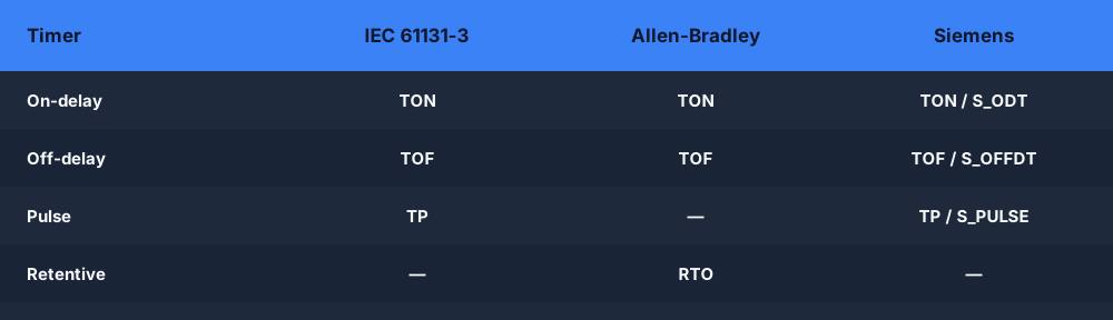
Note Allen-Bradley's RTO (retentive on-delay), which keeps its accumulated time when the rung goes false — you must clear it with a RES instruction. There is no separate retentive block in plain IEC; you build the same behaviour from a TON and a latch.
Common timer mistakes
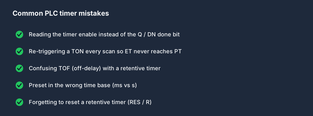
Most timer "faults" on a real machine are one of these five — and almost all of them come back to the scan cycle: a timer is re-enabled every scan, or its done bit is read on the wrong scan.
Where timers show up on real machines
Practice timers in your browser
The fastest way to make timers stick is to wire one up and watch ET climb in real time. You can do exactly that — TON, TOF, TP, CTU/CTD counters and edge detection — in the free browser PLC simulator; switch the ladder logic editor between IEC, Allen-Bradley and Siemens dialects to see the naming differences for yourself.
FAQ
What is the difference between TON and TOF? TON delays the output turning on (Q goes true PT seconds after IN). TOF delays the output turning off (Q goes false PT seconds after IN drops).
What does TP do in a PLC? TP produces a single fixed-length pulse of duration PT on each rising edge of IN, regardless of how long IN stays true.
What is the difference between TON and RTO? A TON resets its elapsed time the instant its input goes false. An RTO (Allen-Bradley retentive on-delay) keeps its accumulated time and must be cleared with a RES instruction.
What are IN, PT, Q and ET on a PLC timer? IN is the enable input, PT is the preset time you are counting to, Q is the done/output bit, and ET is the elapsed time so far.