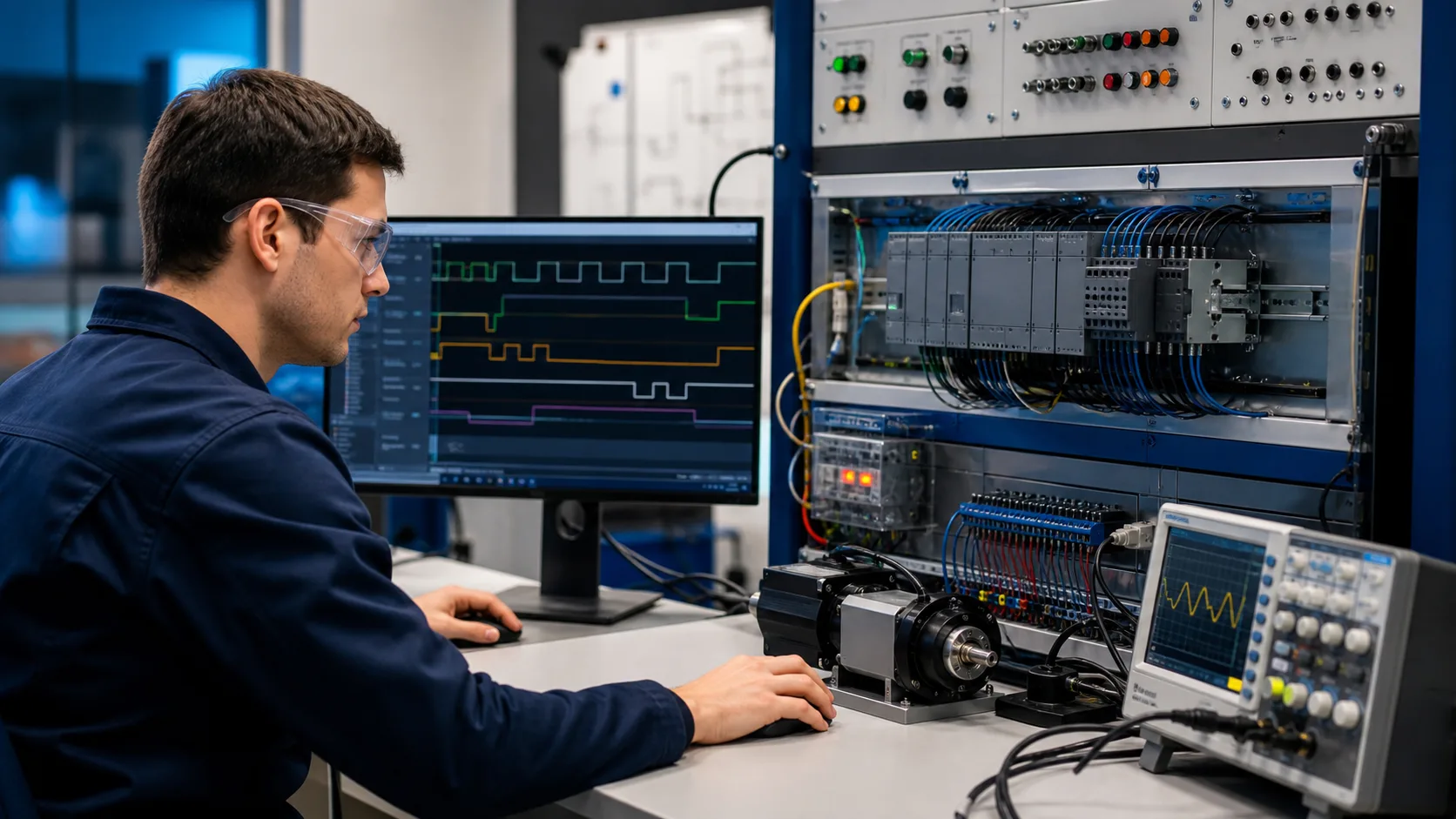
A traffic light is the perfect first sequencing project on a PLC: three outputs, a fixed repeating cycle, and nothing but timers driving the whole thing. Once you can make a lamp turn Red, then Green, then Yellow, then Red again on a clock you control, you understand the core of every sequential machine — a packaging line, a car wash, a batch reactor. This tutorial designs a single-intersection signal from scratch, with the I/O list, the state diagram, the timing, and the exact ladder rungs.
We will keep the engineering honest: only one lamp is ever on, Yellow appears only between Green and Red (never on the way to Green), and the whole sequence loops forever from a single timer chain.

The I/O list
Before any logic, list what the PLC drives and senses. A basic single-direction signal needs three discrete outputs — one per lamp — and, if you want a pedestrian crossing, a single discrete input for the push button.
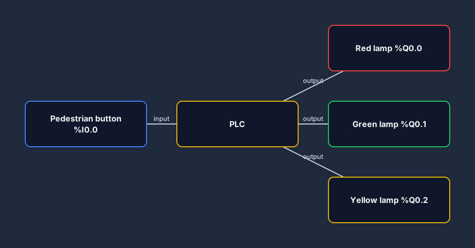
| Signal | Address | Type | Notes |
|---|---|---|---|
| Red lamp | %Q0.0 | Output | On the longest — it is the safe default |
| Green lamp | %Q0.1 | Output | The "go" interval |
| Yellow lamp | %Q0.2 | Output | Short clearance interval before Red |
| Pedestrian button | %I0.0 | Input | Optional, momentary — requests a crossing |
Three outputs, one optional input. That is the entire hardware story. Everything else is timing logic inside the CPU.
The state sequence
A traffic light is a state machine: at any instant the intersection is in exactly one state, and each state automatically advances to the next after a fixed time. Map the states before you touch ladder logic — it makes the rungs obvious later.
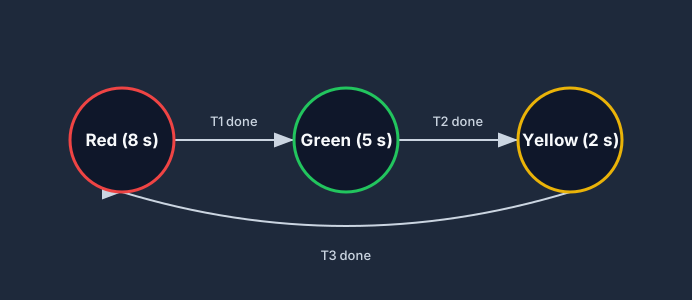
There are only three states and the transitions are one-directional, forming a loop:
- Red → after its time, go to Green
- Green → after its time, go to Yellow
- Yellow → after its (short) time, go back to Red
Notice there is no Yellow between Red and Green. Real signals jump straight from Red to Green; Yellow is purely a clearance warning that Red is coming. Getting this wrong is the most common beginner mistake.
Choosing the timing
Pick a duration for each state. The numbers below are a sensible demo cycle; real intersections tune these to traffic volume and approach speed, but the structure is identical.
| State | Duration | Why |
|---|---|---|
| Red | 8 s | Default safe state; longest interval |
| Green | 5 s | Vehicles proceed |
| Yellow | 2 s | Short clearance before Red |
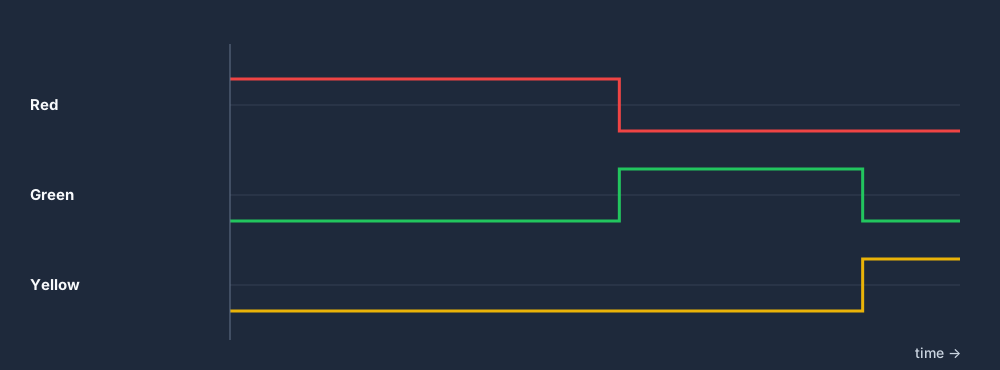
That makes a 15-second total cycle that repeats forever. Plot the three outputs across one full cycle and the discipline of the design becomes visible: at every moment exactly one lamp is energised, and the on-periods never overlap.
The timer chain idea
The cleanest way to build a fixed-time sequence is a chain of TON (on-delay) timers, where each timer's done bit enables the next. If you are shaky on how an on-delay timer counts up to its preset and sets a done bit, read the PLC timers guide first — this whole program is just three of them in a row.
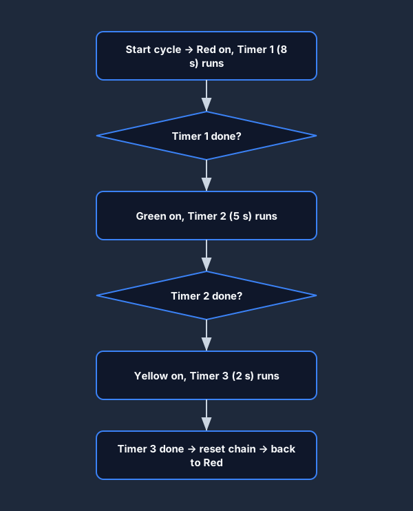
The chain runs like this:
- The sequence starts (or restarts) and Timer 1 begins counting the Red interval.
- When Timer 1 is done, Timer 2 starts counting the Green interval.
- When Timer 2 is done, Timer 3 starts counting the Yellow interval.
- When Timer 3 is done, the whole chain resets and Red begins again.
We then derive each lamp output from which timers have finished. A lamp is on during the window between the previous timer finishing and the next timer finishing.
Building the ladder logic
Here is the heart of the program. We use three timers — T1 (Red, 8 s), T2 (Green, 5 s) and T3 (Yellow, 2 s) — chained so each starts when the previous finishes, and we restart the cycle when T3 completes.
Rung 1 — Red lamp
Red is the default state, so it is on from the start of the cycle until Timer 1 finishes. Drive the Red lamp from the not-done condition of T1: while T1 is still counting, Red is on. We seal in the cycle so it free-runs.
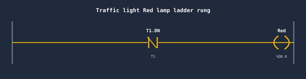
In plain terms: Red is on while Timer 1 has not yet timed out. The instant T1 reaches its 8-second preset, its done bit ends the Red window and enables Timer 2.
Rung 2 — Green lamp
Green is on during the window after T1 is done but before T2 is done. Use T1's done bit (timing is finished, Green may run) in series with T2's not-done bit (Green's own timer is still counting).
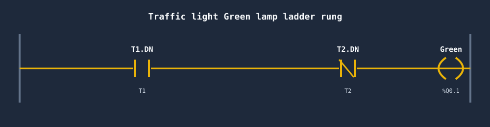
So Green is on when T1 is done AND T2 is not done. That single AND gives you a clean 5-second Green that can never overlap Red.
Rung 3 — Yellow lamp
Yellow occupies the last window: after T2 is done but before T3 is done. Same pattern again — T2's done bit in series with T3's not-done bit.
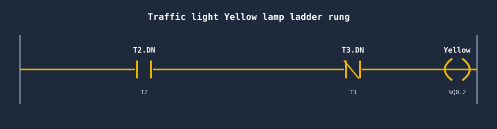
Yellow is on when T2 is done AND T3 is not done. When T3 finally times out, its done bit resets the whole chain, T1 starts again, and Red returns. The intersection cycles forever with no external trigger.
Wiring the timers
The three TON timers form the backbone. T1 is enabled by the running cycle, T2 by T1.DN, and T3 by T2.DN. The single rung that resets everything uses T3.DN to drop the cycle latch for one scan, which restarts T1 — and away it goes again.
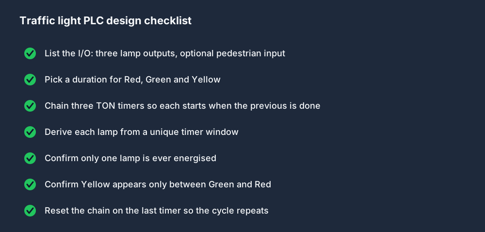
A design checklist
Before you call any sequence "done", walk this list. It catches the bugs that make a traffic light flash two lamps at once or skip Yellow.
Fixed-time vs sensor-actuated
The program above is fixed-time: every cycle is identical. Real intersections are often sensor-actuated — inductive loops or cameras detect waiting vehicles and the controller extends Green or skips an empty approach. The pedestrian button in our I/O list is the simplest form of actuation: pressing it can shorten Green and force the Red/clearance sequence sooner.
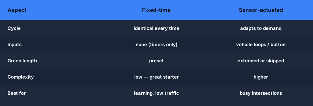
Start with fixed-time. Once it cycles cleanly, adding a pedestrian request is a small extension: latch the button press, and let it cut the Green timer's effective preset short.
Where this pattern shows up
The chained-timer sequence you just built is not a toy. The same structure runs everywhere a machine steps through fixed-time stages.

Build it in your browser
Reading the rungs is one thing; watching the lamps actually cycle is what makes it click. The fastest way to see this work is to wire it in a free browser PLC simulator — drop in three TON timers, chain their done bits, and step the scan to watch Red give way to Green, Green to Yellow, and Yellow back to Red in real time.
The product ships a ready-made Traffic Light challenge in the free scenarios library, complete with animated lamps and pass/fail checks — open it, build the timer chain from this tutorial, and confirm only one lamp is ever lit. It is the cleanest possible introduction to sequential PLC programming.
FAQ
What ladder logic do you need for a traffic light? Three TON (on-delay) timers chained together — one for Red, one for Green, one for Yellow. Each lamp output is driven by the window between two timers' done bits, and the last timer's done bit resets the chain so the cycle repeats.
Why does a traffic light PLC program use timers instead of counters? A signal is a time-based sequence: each state lasts a fixed number of seconds. Timers count elapsed time directly, so they map onto the sequence one-to-one. Counters track events, which is the wrong primitive here.
In what order do the lamps turn on? Red → Green → Yellow → Red, looping forever. Yellow appears only between Green and Red as a clearance interval — never between Red and Green. Real signals go straight from Red to Green.
How do I make sure only one lamp is on at a time? Derive each lamp from a unique timer window: Red while T1 is not done, Green when T1 is done and T2 is not, Yellow when T2 is done and T3 is not. Because the windows don't overlap, exactly one lamp is energised at any instant.