E-Stop Circuit (Cat 3 / Cat 4)
A dual-channel monitored emergency stop circuit that safely removes power from hazardous motion and detects single-point failures.
01 / Recognize it
What this sensor looks like
Learn the housing, active face, mounting, and connector before you meet it on a machine.

Hardware recognition
Know what to look for
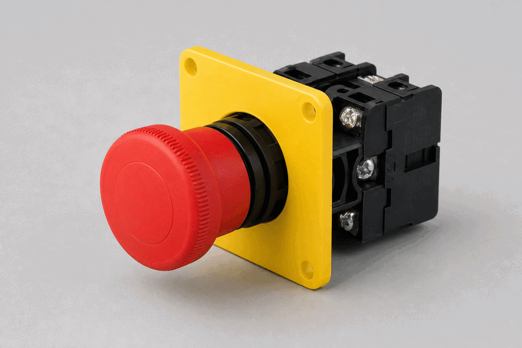
Use the silhouette, active face, and connection style to identify the device before checking its part number and datasheet.
- Body and mounting
- A large red mushroom actuator sits on a yellow background or enclosure.
- Active face
- The actuator latches when pressed and normally twists or pulls to release.
- Cable and terminals
- Behind the panel, positively driven NC contact blocks form two channels.
02 / Understand the principle
Watch cause become a PLC signal
Follow the physical event through the sensing element and into the exact controller value.
Signal story / live loop
E-Stop Circuit (Cat 3 / Cat 4): cause to controller
Now showingPhysical event
Operator presses E-stop → Both NC channels open → %I0.6–0.7 = 0
03 / Test and commission it
Commission it on the bench
Move the process, adjust the setpoint, invert the logic and inject faults. Watch the PLC value respond immediately.
Commissioning bench
E-Stop Circuit (Cat 3 / Cat 4)
PLC channel
%I0.6–0.7
RAW 1
Engineering value
35 %
Safety channels
Channel healthy
Hazard detected: both safety outputs must drop
Commissioning note: Test both channels independently and confirm reset never restarts hazardous motion.
Field guide
An emergency stop (e-stop) circuit must be designed to a defined safety performance level. Category 3 (Cat 3) requires that a single component failure does not lead to loss of safety function — a second failure before the first is repaired may cause loss of safety. Category 4 (Cat 4) requires that even a combination of failures does not lead to loss of safety.
The dual-channel wiring principle achieves this. The e-stop button has two NC contacts wired in separate channels. Both channels must be simultaneously de-energised before the safety relay drops out. A safety relay module (or safety PLC) monitors both channels continuously and will not allow a restart if the two channels are not consistent — for example, if one channel is open and the other is still closed.
Cross-channel monitoring detects short circuits between channels, which is a common failure mode when cable insulation is damaged. The safety relay tests for cross-shorts by momentarily pulsing each channel and verifying the other does not follow.
A manual restart interlock is required for Cat 4: the machine must not restart automatically when the e-stop is released — an operator must consciously press a separate reset button. This prevents an unexpected restart that could injure someone who was inside the danger zone when the e-stop was activated.
Wiring e-stops in series on each channel allows multiple buttons — at pendants, along conveyors, at panel doors — to all stop the machine safely regardless of which one is activated.
Use this when…
- Providing operator emergency stop on any machine that could cause injury
- Creating a Category 3 or 4 safety circuit for PLd or SIL2 compliance
- Monitoring the wiring integrity of safety devices in a control panel
Where you will see it
Robot cell
Dual-channel e-stop circuits at each robot access point drop the safety relay simultaneously, de-energising servo drives in < 20 ms.
Conveyor system
Pull-cord e-stops along a long conveyor run are wired in series on both channels; activating any cord opens both channels.
Next skill
Connect it to PLC logic
Unlock PLC integration challenges