PLC Simulator
Protocol workbench

Modbus Simulator

Run real Modbus request exercises before you connect a PLC, drive or meter.

Run before signup Server-graded Save, share and fork
Open the workbench
industrial-lab / modbus
MODETRAINING
GRADERSERVER AUTHORITY
EVIDENCECHECKS + SCORE

First challenge

Read two holding registers

Poll unit 1 for the first two holding registers using the protocol data address.

Real Modbus simulator footage

See this exact skill in the working simulator.

Watch the real browser product respond to the task on this page, then try the same practical workflow yourself. No slides, concept mockups, install, or credit card.

Try this in the browser
Modbus Simulator — See the RS-485 Signal Path in the Real Lab

Read the request from wire to application

Prove the Modbus map before blaming the network.

Modbus troubleshooting becomes predictable when you separate transport, unit identity, function, protocol address, data representation and application behavior. These views follow the same sequence used in the interactive workbench.
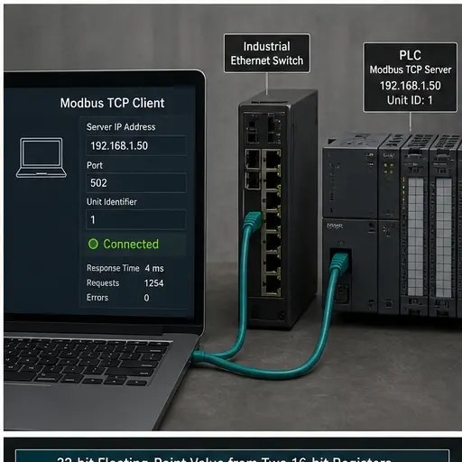
Modbus TCP client connected through an industrial Ethernet switch to a PLC server
01Start with the client, server address, TCP port and unit identifier, then save a known-good response baseline.
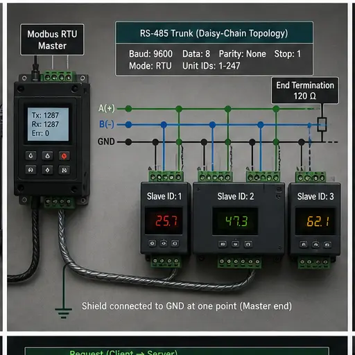
Modbus RTU master and three slave devices wired as an RS-485 daisy chain with shield and termination
02For RTU, prove baud, framing, device IDs, polarity, trunk topology and end termination before changing registers.
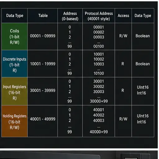
Modbus coils discrete inputs input registers and holding registers compared with protocol addresses
03Translate human-facing 0xxxx, 1xxxx, 3xxxx and 4xxxx references into the zero-based address placed in the request.
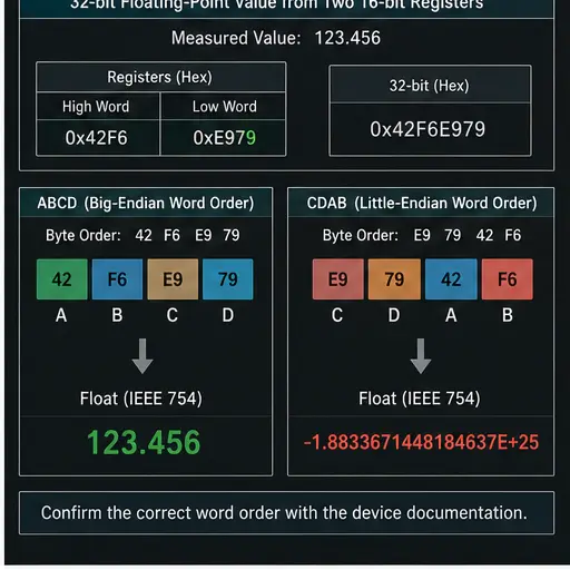
Thirty-two-bit floating-point Modbus value decoded from two 16-bit registers using different word orders
04Data can arrive successfully and still be wrong. Confirm type, byte order, word order and scaling from the device manual.
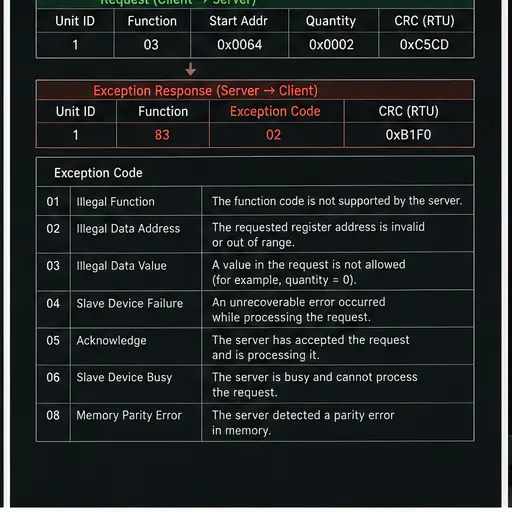
Modbus exception response showing illegal function and illegal data address diagnostic codes
05An exception proves the device understood enough to reject the request—use the code to narrow the configuration fault.
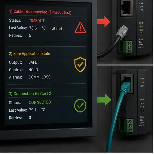
Modbus cable disconnect test showing timeout stale data safe state and restored communication
06Test retries, stale-data indication, application safe state and recovery rather than accepting one successful poll.

Interactive request lab

Configure. Run. Read the evidence.

Foundation

Read two holding registers

Poll unit 1 for the first two holding registers using the protocol data address.

Evidence appears here

The backend calculates the expected result and returns individual checks, a score and reproducible evidence. Client-supplied scores are ignored.

Your run is free. Keep the evidence when it matters.

Create an account only when you want saved attempts, projects, sharing and progress.

Save this result

Training outcomes

More than a calculator.

Each run teaches a transferable industrial workflow and produces evidence you can inspect, repeat and discuss.

01

Translate 4xxxx register notation into the zero-based address carried on the wire.

02

Choose function 03, 06 and exception responses without vendor-specific software.

03

Save a register-map fixture, share it with a class and fork a colleague’s setup.

04

Build evidence from graded attempts instead of relying on a self-marked worksheet.

Field method

How to reason through the lab

STEP 01

Register notation is not the wire address

A manual may label a holding register 40001, but the Modbus application data unit normally carries address 0. Confirm whether a vendor table is one-based or zero-based before blaming the network.

STEP 02

Start with one known-good request

Prove the unit ID, function, address and quantity with the smallest possible poll. Expand the block only after the device returns a normal response.

STEP 03

Read the exception byte

An exception response is useful evidence. Function 83 with code 02 means the device understood a function-03 request but the requested address range was not mapped.

Continue from a single exercise to a complete training record.

Guided scenarios, saved progress, fault diagnosis and instructor reporting are built into the main platform.

Compare training plans

Technical practice library

Load a real job, not an empty calculator.

Each reference explains a distinct industrial task and links back to an exact grader preset with server-owned acceptance evidence.

Browse all training exercises

Variable-frequency drive

Read VFD Output Frequency With Modbus Function 03

Compose a Modbus request for a VFD output-frequency holding register and verify the zero-based address and quantity.

Energy meter

Read an Energy Meter With Modbus Function 04

Build a two-register input-register poll for a 32-bit energy-meter value and retain word-order evidence.

Panel temperature controller

Read a Temperature Controller Process Value Over Modbus

Compose a function-03 poll for a scaled temperature process value at protocol address 200.

Remote-I/O coupler

Read 16 Remote-I/O Coils With Modbus Function 01

Build a packed 16-coil function-01 poll and verify the bit quantity and zero-based start address.

Remote-I/O digital-input module

Read 16 Remote-I/O Inputs With Modbus Function 02

Compose a Modbus function-02 request for 16 read-only remote-I/O inputs and verify the address, quantity and packed-bit evidence.

Pump controller

Write a Pump Run Coil With Modbus Function 05

Encode an ON command as FF00 for a documented pump run coil and verify the function-05 request.

Temperature controller

Write a Temperature Setpoint With Modbus Function 06

Compose a single-register setpoint write and preserve the distinction between engineering units and the scaled register value.

Alarm annunciator

Write an Alarm Reset Block With Modbus Function 15

Build a packed eight-coil function-15 write and check quantity, byte count and ownership boundaries.

Technical review

Primary references used for this lab

Reviewed 7 August 2026. The simulator teaches a repeatable training method; always use the exact module and instrument manuals for live commissioning work.

Modbus Simulator questions

What learners and instructors ask.

The exercises teach the shared Modbus application protocol used by both. The request grader covers unit IDs, function codes, data addresses, quantities, values and exceptions; the tutorials explain TCP transaction framing and RTU serial timing separately.

Industrial communications field guide

Modbus simulator: data contract, commissioning and diagnosis

Direct answer

Modbus simulator is learned by making the data contract explicit: client request, server response, unit identifier, function code, starting address, quantity and data. Successful packets are not enough; verify that coils, discrete inputs, input registers and holding registers represent the intended engineering state and that loss, stale data and recovery produce defined application behavior.

This guide is written for controls technicians and engineers commissioning controller-to-device or controller-to-software communications. The intended result is specific: the learner can separate physical link, network identity, transport/session, protocol request, data mapping and application behavior, then find the first failing layer.

System map / 02

Six concepts that control the result

Treat these as connected checkpoints. Each checkpoint has an expected state, an observable state and a boundary to the next part of the system. That structure prevents a software indication from being mistaken for physical proof.

NODE 01observable

Role ownership

Name each endpoint and which side initiates, serves, produces or consumes data within client request, server response, unit identifier, function code, starting address, quantity and data.

NODE 02observable

Identity and path

Prove the exact endpoint and device identity before debugging the payload.

NODE 03observable

Data model

Map coils, discrete inputs, input registers and holding registers into typed engineering tags with direction, units and ownership.

NODE 04observable

Update behavior

Document cyclic, polled, subscribed or event behavior plus timing and timeout.

NODE 05observable

Quality and stale state

A value needs freshness and communication state; last-known data must not masquerade as current truth.

NODE 06observable

Recovery

Test disconnect, restart, reconnection, resubscription or connection establishment and application safe response.

Procedure / 03

A six-step practice and commissioning workflow

Run the steps in order the first time. Later, the same structure becomes a diagnostic loop: define the expected condition, observe the boundary, interpret the difference and choose one proving action.

  1. 01

    Draw the topology

    Name endpoints, switches, media, addressing and ownership.

    Evidence: The intended path is unambiguous.

    Avoid: Beginning with random software settings.

  2. 02

    Verify the physical layer

    Check power, link, media, topology and port state.

    Evidence: Basic connectivity is proven.

    Avoid: Treating a link light as application success.

  3. 03

    Verify identity

    Confirm address, name, device/revision and endpoint role.

    Evidence: The configuration targets the intended device.

    Avoid: Connecting to the wrong but reachable endpoint.

  4. 04

    Match the contract

    Compare client request, server response, unit identifier, function code, starting address, quantity and data at both ends.

    Evidence: Direction, size and identifiers agree.

    Avoid: Changing multiple fields simultaneously.

  5. 05

    Prove engineering data

    Operate one real or simulated input and map coils, discrete inputs, input registers and holding registers.

    Evidence: The expected tag changes with correct type and units.

    Avoid: Accepting a successful status with wrong data.

  6. 06

    Test failure and return

    Disconnect deliberately under an approved test and restore.

    Evidence: Timeout, safe state, stale indication and recovery pass.

    Avoid: Testing only startup success.

Diagnostic matrix / 04

Symptoms, proving points and next actions

The table is a reasoning aid, not a parts-replacement chart. Preserve the initial symptom, inspect the named boundary and use the interpretation to choose the next controlled test. Site safety procedures and equipment manuals remain authoritative.

Diagnostic symptoms, inspection points, interpretations and next actions for Modbus simulator: data contract, commissioning and diagnosis
Observed symptomInspectInterpretationNext proving action
No physical linkPower, media, connector, switch and port stateThe failure is below protocol configuration.Restore link first.
Reachable but no session/connectionEndpoint role, identity, security or connection parametersNetwork path works while protocol establishment fails.Read exact status and logs.
Protocol exception or rejectFunction/service, object/address and client request, server response, unit identifier, function code, starting address, quantity and dataThe peer understood enough to reject a request.Use the returned diagnostic.
Data changes but is wrongType, direction, byte/word mapping, scale and coils, discrete inputs, input registers and holding registersTransport succeeds while interpretation fails.Compare a known pattern.
Intermittent timeoutLoad, update rate, topology, errors and resource limitsTiming margin or physical quality may be unstable.Capture counters and timestamps.
Reconnect leaves stale stateTimeout policy, quality, resubscription/reconnection and application stateCommunication returned without restoring the data contract.Test complete recovery sequence.

Product evidence / 05

What the browser practice can actually demonstrate

The public training surface provides vendor-neutral diagrams, mapping examples, staged diagnostics and links into related browser labs without claiming wire-level conformance.

Where simulation stops

A training guide does not certify interoperability, network architecture, cybersecurity or performance. Use current protocol-organization material, device manuals, approved tools and the actual installed topology.

Commissioning notebook / 06

Six cases that turn the concepts into evidence

Use these as written briefs rather than click-through instructions. For every case, state the expected condition before acting, retain the first useful observation and explain why the final result proves the requirement. A different program or component choice can still be correct when it produces the same bounded behavior and evidence.

Case 01

predict → observe → prove

Prove role ownership

Engineering context. Name each endpoint and which side initiates, serves, produces or consumes data within client request, server response, unit identifier, function code, starting address, quantity and data. Begin with a written normal condition and identify which request, state, physical result or communication value will provide independent confirmation. Do not begin by changing the configuration; the initial state is part of the evidence and should remain reproducible.

Controlled setup. Use the “Draw the topology” stage of the workflow: name endpoints, switches, media, addressing and ownership. The acceptance record should show this result: the intended path is unambiguous. Record initial conditions, the exact stimulus and the observation point so another learner can repeat the case without relying on your memory.

Fault challenge. Introduce or analyse “No physical link” as one bounded deviation. Inspect power, media, connector, switch and port state The working interpretation is that the failure is below protocol configuration. The next proving action is to restore link first. Change only one condition before observing the result, and preserve timestamps or measurements where timing matters.

Review and recovery. The most common trap here is beginning with random software settings. After restoring the cause, repeat the normal case and at least one stop, timeout, disconnect or restart boundary relevant to this topic. Remove temporary forces and bypasses, return the model to a known state and retain the evidence that both operation and recovery are deliberate.

Explain it aloud: What should I learn first? A defensible short answer is: Start with roles and the exact data contract: client request, server response, unit identifier, function code, starting address, quantity and data.

Case 02

predict → observe → prove

Prove identity and path

Engineering context. Prove the exact endpoint and device identity before debugging the payload. Begin with a written normal condition and identify which request, state, physical result or communication value will provide independent confirmation. Do not begin by changing the configuration; the initial state is part of the evidence and should remain reproducible.

Controlled setup. Use the “Verify the physical layer” stage of the workflow: check power, link, media, topology and port state. The acceptance record should show this result: basic connectivity is proven. Record initial conditions, the exact stimulus and the observation point so another learner can repeat the case without relying on your memory.

Fault challenge. Introduce or analyse “Reachable but no session/connection” as one bounded deviation. Inspect endpoint role, identity, security or connection parameters The working interpretation is that network path works while protocol establishment fails. The next proving action is to read exact status and logs. Change only one condition before observing the result, and preserve timestamps or measurements where timing matters.

Review and recovery. The most common trap here is treating a link light as application success. After restoring the cause, repeat the normal case and at least one stop, timeout, disconnect or restart boundary relevant to this topic. Remove temporary forces and bypasses, return the model to a known state and retain the evidence that both operation and recovery are deliberate.

Explain it aloud: Does a successful connection prove correct data? A defensible short answer is: No. Verify direction, type, scale, units, quality and physical meaning.

Case 03

predict → observe → prove

Prove data model

Engineering context. Map coils, discrete inputs, input registers and holding registers into typed engineering tags with direction, units and ownership. Begin with a written normal condition and identify which request, state, physical result or communication value will provide independent confirmation. Do not begin by changing the configuration; the initial state is part of the evidence and should remain reproducible.

Controlled setup. Use the “Verify identity” stage of the workflow: confirm address, name, device/revision and endpoint role. The acceptance record should show this result: the configuration targets the intended device. Record initial conditions, the exact stimulus and the observation point so another learner can repeat the case without relying on your memory.

Fault challenge. Introduce or analyse “Protocol exception or reject” as one bounded deviation. Inspect function/service, object/address and client request, server response, unit identifier, function code, starting address, quantity and data The working interpretation is that the peer understood enough to reject a request. The next proving action is to use the returned diagnostic. Change only one condition before observing the result, and preserve timestamps or measurements where timing matters.

Review and recovery. The most common trap here is connecting to the wrong but reachable endpoint. After restoring the cause, repeat the normal case and at least one stop, timeout, disconnect or restart boundary relevant to this topic. Remove temporary forces and bypasses, return the model to a known state and retain the evidence that both operation and recovery are deliberate.

Explain it aloud: How should communication faults be diagnosed? A defensible short answer is: Move layer by layer from physical link and identity through protocol status, mapping and application behavior.

Case 04

predict → observe → prove

Prove update behavior

Engineering context. Document cyclic, polled, subscribed or event behavior plus timing and timeout. Begin with a written normal condition and identify which request, state, physical result or communication value will provide independent confirmation. Do not begin by changing the configuration; the initial state is part of the evidence and should remain reproducible.

Controlled setup. Use the “Match the contract” stage of the workflow: compare client request, server response, unit identifier, function code, starting address, quantity and data at both ends. The acceptance record should show this result: direction, size and identifiers agree. Record initial conditions, the exact stimulus and the observation point so another learner can repeat the case without relying on your memory.

Fault challenge. Introduce or analyse “Data changes but is wrong” as one bounded deviation. Inspect type, direction, byte/word mapping, scale and coils, discrete inputs, input registers and holding registers The working interpretation is that transport succeeds while interpretation fails. The next proving action is to compare a known pattern. Change only one condition before observing the result, and preserve timestamps or measurements where timing matters.

Review and recovery. The most common trap here is changing multiple fields simultaneously. After restoring the cause, repeat the normal case and at least one stop, timeout, disconnect or restart boundary relevant to this topic. Remove temporary forces and bypasses, return the model to a known state and retain the evidence that both operation and recovery are deliberate.

Explain it aloud: What is stale data? A defensible short answer is: It is a previously valid value that is no longer being updated within the required freshness contract.

Case 05

predict → observe → prove

Prove quality and stale state

Engineering context. A value needs freshness and communication state; last-known data must not masquerade as current truth. Begin with a written normal condition and identify which request, state, physical result or communication value will provide independent confirmation. Do not begin by changing the configuration; the initial state is part of the evidence and should remain reproducible.

Controlled setup. Use the “Prove engineering data” stage of the workflow: operate one real or simulated input and map coils, discrete inputs, input registers and holding registers. The acceptance record should show this result: the expected tag changes with correct type and units. Record initial conditions, the exact stimulus and the observation point so another learner can repeat the case without relying on your memory.

Fault challenge. Introduce or analyse “Intermittent timeout” as one bounded deviation. Inspect load, update rate, topology, errors and resource limits The working interpretation is that timing margin or physical quality may be unstable. The next proving action is to capture counters and timestamps. Change only one condition before observing the result, and preserve timestamps or measurements where timing matters.

Review and recovery. The most common trap here is accepting a successful status with wrong data. After restoring the cause, repeat the normal case and at least one stop, timeout, disconnect or restart boundary relevant to this topic. Remove temporary forces and bypasses, return the model to a known state and retain the evidence that both operation and recovery are deliberate.

Explain it aloud: Should I increase timeouts first? A defensible short answer is: No. Preserve evidence and identify physical, load, configuration or processing causes before masking them.

Case 06

predict → observe → prove

Prove recovery

Engineering context. Test disconnect, restart, reconnection, resubscription or connection establishment and application safe response. Begin with a written normal condition and identify which request, state, physical result or communication value will provide independent confirmation. Do not begin by changing the configuration; the initial state is part of the evidence and should remain reproducible.

Controlled setup. Use the “Test failure and return” stage of the workflow: disconnect deliberately under an approved test and restore. The acceptance record should show this result: timeout, safe state, stale indication and recovery pass. Record initial conditions, the exact stimulus and the observation point so another learner can repeat the case without relying on your memory.

Fault challenge. Introduce or analyse “Reconnect leaves stale state” as one bounded deviation. Inspect timeout policy, quality, resubscription/reconnection and application state The working interpretation is that communication returned without restoring the data contract. The next proving action is to test complete recovery sequence. Change only one condition before observing the result, and preserve timestamps or measurements where timing matters.

Review and recovery. The most common trap here is testing only startup success. After restoring the cause, repeat the normal case and at least one stop, timeout, disconnect or restart boundary relevant to this topic. Remove temporary forces and bypasses, return the model to a known state and retain the evidence that both operation and recovery are deliberate.

Explain it aloud: Can this browser guide test conformance? A defensible short answer is: No. It teaches concepts and diagnosis; formal conformance needs approved specifications and test programs.

Answer surface / 07

Questions people ask about Modbus simulator

These concise answers define the operating, training and product boundaries most often missed in broad summaries. The full workflow and diagnostic table above provide the evidence behind them.

What should I learn first?

Start with roles and the exact data contract: client request, server response, unit identifier, function code, starting address, quantity and data.

Does a successful connection prove correct data?

No. Verify direction, type, scale, units, quality and physical meaning.

How should communication faults be diagnosed?

Move layer by layer from physical link and identity through protocol status, mapping and application behavior.

What is stale data?

It is a previously valid value that is no longer being updated within the required freshness contract.

Should I increase timeouts first?

No. Preserve evidence and identify physical, load, configuration or processing causes before masking them.

Can this browser guide test conformance?

No. It teaches concepts and diagnosis; formal conformance needs approved specifications and test programs.

Why test disconnects?

Real systems lose links. The control response, indication and recovery are part of the design.

What evidence belongs in commissioning?

Topology, identities, configuration, mapped points, timing baseline, fault response and recovery results.