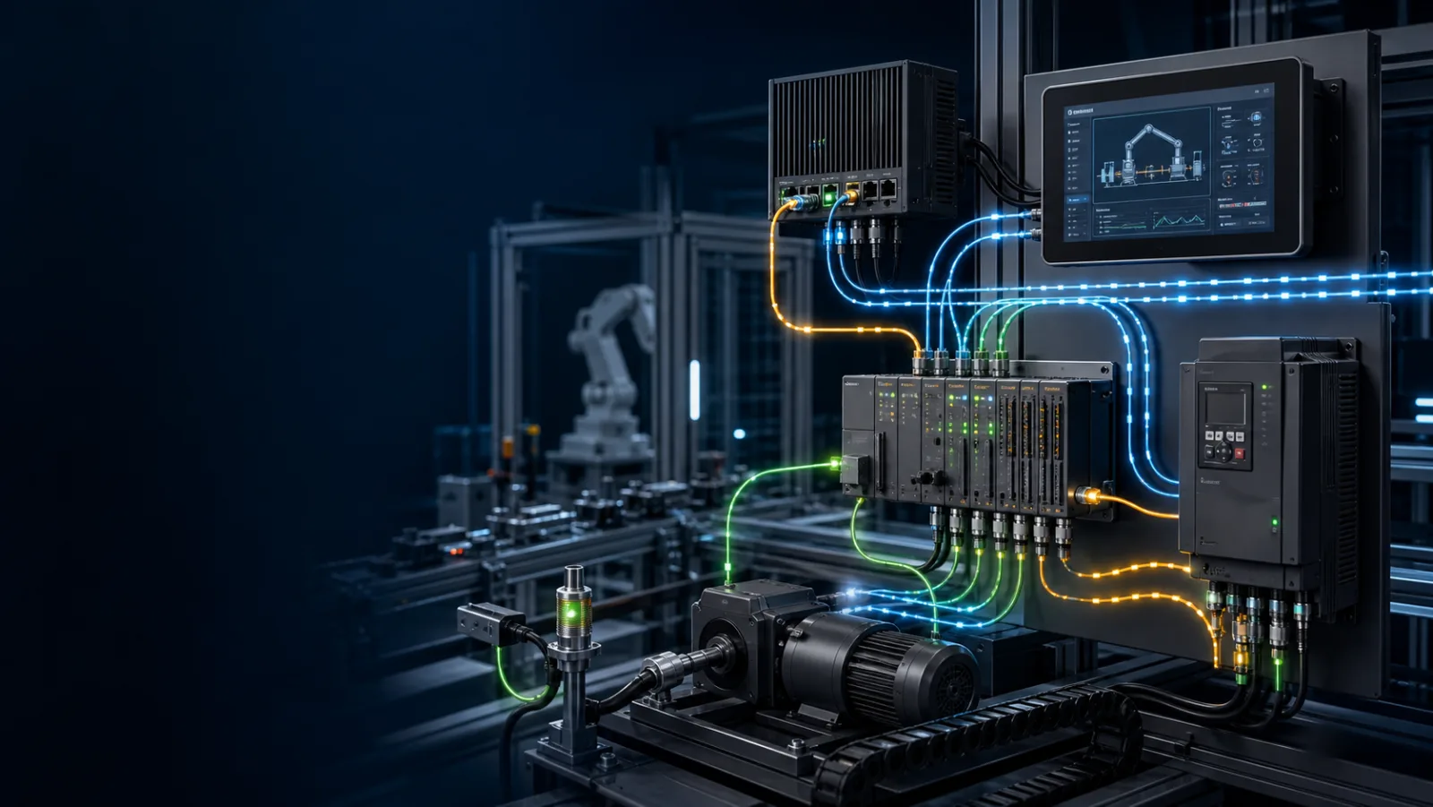
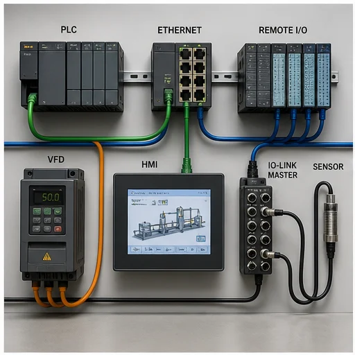
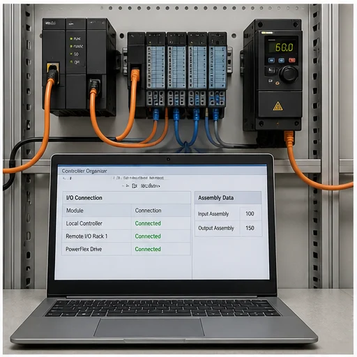
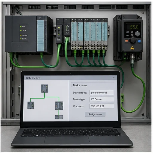
Commission from physical link to process evidence
Start with the information job, not the connector
Industrial communication protocol selection starts with a precise sentence: which producer must deliver which information to which consumer, within what time, and what must happen when delivery fails? “The machine needs Ethernet” is not a requirement. “The controller must exchange a 32-byte input assembly and a 16-byte output assembly with remote I/O every 20 ms, detect loss within 200 ms, and drive outputs to the reviewed safe state” is a requirement that an engineer can configure and test.
EtherNet/IP and PROFINET are industrial Ethernet systems commonly used for cyclic controller-to-device process data. IO-Link connects one master port to one compatible sensor or actuator and adds parameters, identity and diagnostics to the field connection. OPC UA exposes an information model to software clients through browsable nodes, typed values, events, methods and subscriptions. These technologies overlap at some boundaries, but they are not interchangeable labels for the same job.
Separate four layers when drawing the architecture. The physical layer covers cable, connector, power, shielding and switch port. Identity covers device name, IP settings, vendor and product identity, revision and certificates. Data-contract configuration covers modules, assemblies, process-data lengths, byte order, types and update behavior. The application layer covers what the controller, HMI, historian or analytic service actually does with valid, uncertain, stale or missing data. A green link light proves only part of the first layer.
| Technology | Primary job | Typical relationship | Configuration evidence | Failure evidence |
|---|---|---|---|---|
| EtherNet/IP | Cyclic I/O plus CIP configuration and diagnostics | Scanner to adapter | EDS/profile, identity, assembly instances, byte lengths, RPI | Connection state, timeout, module status, safe output response |
| PROFINET | Cyclic controller-to-device I/O plus acyclic records and diagnostics | IO controller to IO device | GSDML, station name, device/module layout, update time | Diagnostic alarm, device state, substitute-value behavior |
| IO-Link | Point-to-point smart sensor or actuator data | Master port to one device | IODD, port mode, process-data map, parameters | Port/device status, quality, replacement and parameter-restore result |
| OPC UA | Structured, secure information exchange between applications and equipment | Client to server or PubSub participants | Endpoint, namespace, NodeIds, types, certificates, permissions | StatusCode, timestamps, stale indication, reconnect and audit evidence |
Cyclic I/O, explicit requests and subscriptions answer different timing questions
Cyclic process data is a repeated contract. A controller and device agree on the bytes or modules to exchange, then update them at a configured interval. The application usually consumes an input image and writes an output image instead of constructing a fresh request for every value. This model suits control signals whose age and loss behavior must be predictable. It does not make every value safety-rated or hard real-time; those properties require an appropriate protocol profile, architecture, devices and validation.
Request-and-response communication is a different pattern. A client asks for an attribute, register, parameter or diagnostic record when it needs one. This is efficient for commissioning values, recipes and information that does not belong in every cyclic packet. A subscription adds another pattern: the client creates monitored items and the server reports values according to sampling, queue and publishing settings. That can reduce polling, but the engineer still has to define acceptable data age and what the consuming application shows when updates stop.
Do not compare update rates without comparing the full behavior. A nominal 10 ms interval says nothing about network load, task scheduling, input filtering, device conversion time, output update, timeout multiplier or application reaction. Document the process response that matters—such as valve command to proved feedback—then budget each stage. In a historian path, document source timestamp, server timestamp, StatusCode and acceptable gap. Timing belongs to the end-to-end data path, not just the protocol brochure.
A useful timing requirement names the signal, normal update interval, maximum acceptable age, loss-detection time, fallback state and recovery rule. “Fast Ethernet” names none of them.
EtherNet/IP: prove the CIP connection and its assemblies
EtherNet/IP uses the Common Industrial Protocol at the application layer over standard Ethernet and the Internet Protocol suite. In controller I/O, the originating device is commonly described as a scanner and the field device as an adapter. A connection may exchange input and output assemblies cyclically. Engineering details commonly include device identity, electronic keying policy, assembly instance numbers, configuration data, input and output byte lengths, Requested Packet Interval and unicast or multicast behavior.
A reachable adapter can still reject the I/O connection. The configured product or revision may not match. An assembly number may be correct for a different operating mode. Input and output length may include or omit status words. The controller can interpret the bytes in the wrong order or data type even while the connection reports healthy. The commissioning record should therefore show the exact device manual/profile used, configured connection parameters, controller diagnostic, raw data map and a physical transition tied to a named tag.
For a drive, prove more than a changing speed word. Confirm the drive command source, reference source, control and status word definitions, scale, units, run permissives and communication-loss action. Command a reviewed low-risk state, observe status and physical response, then create an approved loss condition and verify timeout plus recovery. The device-specific guide remains authoritative; the generic protocol only supplies the transport and object model.
- Identify scanner and every adapter
- Record exact vendor, product code and revision
- Verify assembly instances and byte counts at both ends
- Justify RPI from process need and network capacity
- Map quality and connection status into application logic
- Test loss and reconnection without bypassing safety controls
PROFINET: identity begins with the station name
PROFINET engineering typically models an IO controller, configured IO devices, modules, submodules and channels. A GSDML file describes the device choices available to the engineering system. During commissioning, the configured station name is central to device identification; assigning only the intended IP address is not sufficient evidence that the controller has found the intended device. Compare the physical device, assigned name and engineering configuration before changing unrelated network settings.
A healthy cyclic relationship depends on the installed module and submodule order matching the configured layout. If a remote-I/O slice is installed in the wrong position, the device may be reachable yet report a configuration difference or unavailable channel. Read the controller and device diagnostics at the module and channel level. Save the expected layout and the actual diagnostic, then operate a real input and output so the process image is proven end to end.
Update time, reduction ratio, watchdog behavior, topology expectations and redundancy options depend on the controller, device and conformance capabilities. Choose them from process requirements and current product documentation. For device replacement, write down how the replacement receives its name and parameters, how the controller validates it, what outputs do before the relationship returns and which checks an authorised technician completes before enabling motion.
IO-Link: preserve identity, units and parameter ownership
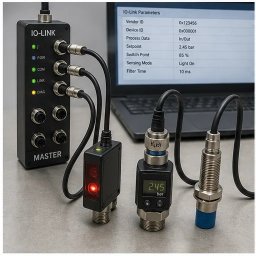
IO-Link is a point-to-point digital communication system between one master port and one device. The master connects the device upward to a fieldbus or industrial Ethernet network; the individual IO-Link link is not itself a shared fieldbus. It can carry cyclic process data along with device identity, parameters, events and diagnostics. The IODD describes the device data so an engineering tool can present fields and units consistently.
Commission the electrical and port boundary first. Verify supply class, connector pinout, port mode, current demand and whether the device uses IO-Link communication or a standard switching mode. Then capture vendor, device ID and firmware where available. Decode the process-data length, bit positions, byte order, invalid/status indicators, scale and engineering units before handing tags to application logic. A number that changes is not yet a trustworthy measurement.
Parameter storage and automatic device replacement can reduce downtime, but only if ownership is explicit. Decide whether the master, engineering project, maintenance tool or device is the source of truth. Test a replacement with a controlled spare: confirm compatible identity, parameter download direction, restored value set, process-data validity and any operator acknowledgement. Without that rehearsal, an automatic restore can reproduce an obsolete parameter set just as efficiently as a correct one.
OPC UA: model meaning, trust and stale-data behavior
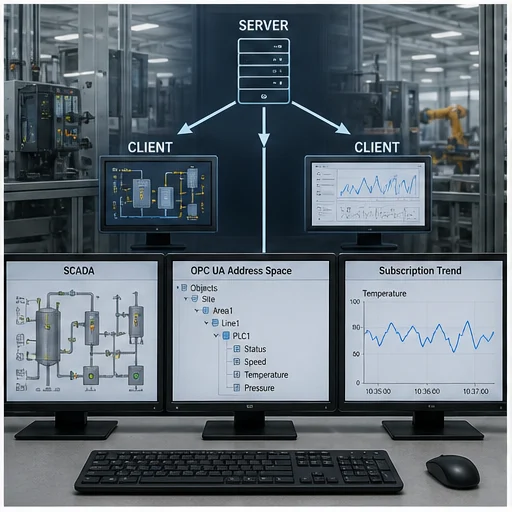
OPC UA is an interoperability framework rather than a flat list of anonymous tags. A server exposes an address space containing nodes, attributes and references. Variables carry data types and StatusCodes; objects can organize equipment; methods and events express behavior beyond a polled value. A client may browse, read, write, call or subscribe according to the server model and granted permissions. The information contract should survive a display-name change because integrations use stable identities such as NodeIds, not a label scraped from a screen.
Security configuration is part of commissioning. Record the endpoint URL, security policy and message security mode, application instance certificates, trust-list approval process, user authentication and role permissions. Do not turn off certificate validation simply to make a test client connect. First verify system time, hostname or endpoint consistency, certificate validity, application identity and the controlled trust workflow. Grant the minimum browse, read, write or method permissions the application needs.
For every important subscribed value, test the bad path. Stop the server or isolate the approved test path and observe the client. Does it retain the last value without marking it stale? Does it use source or server timestamps? Is the StatusCode visible? Does a write queue and replay unexpectedly after reconnect? Define maximum acceptable age, display behavior, control fallback and reconnect acceptance. Connectivity is only successful when consumers handle uncertainty and loss honestly.
| Field | Question it answers | Example evidence |
|---|---|---|
| Identity | Which exact signal is this? | Stable tag/NodeId, device/channel reference, owner |
| Type and scale | How is the value encoded? | BOOL, INT, REAL, bit map, raw span and conversion |
| Units and range | What physical quantity is represented? | bar, °C, rpm, valid minimum and maximum |
| Quality/status | May the consumer trust it now? | Connection state, channel diagnostic, OPC UA StatusCode |
| Time | How old is it? | Source timestamp, server timestamp, cycle or update interval |
| Loss behavior | What happens when it stops arriving? | Timeout, stale presentation, safe substitute and alarm |
Modbus TCP and RTU still matter—but the register map is the contract
Modbus often appears in protocol comparisons because it is widely implemented in meters, drives, gateways and controllers. Modbus RTU commonly uses serial communication; Modbus TCP carries the application protocol over TCP/IP. In both cases, a client requests coils, discrete inputs, input registers or holding registers from a server. The protocol does not provide the rich standardized device model of OPC UA or the cyclic controller-device engineering model of PROFINET and EtherNet/IP.
The difficult part is usually the register contract. Documentation may number a holding register as 40001 while the request uses zero-based address 0. A 32-bit floating-point value spans two 16-bit registers, and devices differ in word order. Signed integers, scale factors, engineering units, read-only status and writable commands must be captured explicitly. Test a known value at the low, middle and high part of the range. Never infer a command register from a nearby readable measurement.
A robust gateway design also preserves failure information. If a Modbus polling gateway loses a downstream meter, it must not continue publishing the last plausible measurement as if it were current. Carry communication state, last-good time and quality alongside the value. Define polling interval, timeout, retries and the load they create. Repeated retries can amplify congestion; an application should alarm on a clear failed state instead of hiding it behind endless requests.
MQTT and Sparkplug belong in the architecture conversation, not the I/O slot
MQTT is a lightweight publish/subscribe messaging protocol built around clients, a broker, topics and quality-of-service choices. It is useful for decoupled event and telemetry distribution, especially when many consumers need plant information. Sparkplug defines conventions for industrial MQTT topic namespaces, payloads and state management. Neither should be described as a generic replacement for a safety function or a controller remote-I/O relationship without a detailed, validated architecture.
Define the publisher of record, topic namespace, payload schema, units, timestamps, retained-message policy, birth/death or availability state, broker security and consumer behavior. A retained last value can help a new subscriber establish context, but it can also look current if the consumer ignores timestamp and publisher state. Quality of Service controls message delivery behavior; it does not prove the process value is fresh, correct or safe.
Use an edge or gateway layer deliberately. Keep deterministic machine control local where the risk assessment and design require it, then publish selected state to supervisory or analytic consumers. Prevent a cloud or enterprise outage from destabilizing the machine. If commands travel downward, require explicit authorization, validation, rate limits and ownership. Segment communication paths and review them under the site cybersecurity program rather than connecting a broker directly to every controller.
Choose with a weighted decision matrix
Begin with mandatory constraints: installed controller ecosystem, supported devices, cycle and latency needs, safety requirements, environmental media, cybersecurity policy, redundancy, maintenance competence and vendor lifecycle. A protocol with elegant features is not a viable choice if the selected controller lacks a maintained implementation or the plant cannot diagnose it at 02:00. Separate must-have constraints from preferences before assigning scores.
Then score shortlisted architectures, not isolated protocol names. One architecture might use IO-Link sensors through a PROFINET master, expose machine objects through OPC UA and publish selected performance events through MQTT. Another might use EtherNet/IP devices and a controller-hosted OPC UA server. Compare engineering effort, diagnostics, spare strategy, testability, license cost, switch and gateway dependencies, change control and the consequences of a component failure.
The winning design needs a commissioning and support plan. List configuration owners, backups, device profiles, certificate renewal, network drawings, managed-switch configuration, replacement process and the signals technicians will use to isolate a fault. If two options score similarly, prefer the one the operating organization can prove, maintain and recover—not the one with the longest feature list.
- Process timing and availability requirements
- Device and controller support over the expected lifecycle
- Diagnostic depth available to maintenance
- Cybersecurity controls and certificate/key operations
- Topology, redundancy and failure containment
- Engineering artifacts, backups and change ownership
- Replacement, recovery and spare-device procedure
- Total support cost rather than connector cost alone
Troubleshoot from the first broken boundary
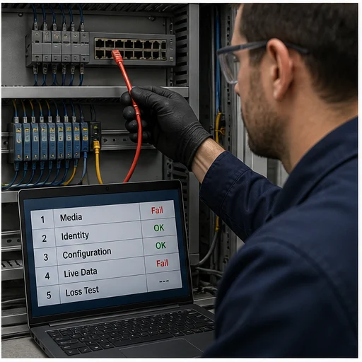
Preserve the first evidence before power cycling. Record controller and device diagnostics, link state, switch-port counters, device identity, connection state, timestamps and the process symptom. Ask which boundary first disagrees with the expected path. No link points toward media, power or port state. Link without identity points toward naming, addressing, duplicate identity or discovery. Identity without an operational data contract points toward profiles, assemblies, modules, data lengths, certificates or permissions.
When communication is operational but the process is wrong, compare raw data to interpreted data. Operate one approved physical input and follow it through device channel, process image, controller tag and consumer. For output testing, begin with the machine in the defined safe state and prove command, status and physical feedback separately. Check scale, signedness, word order, stale status and task/update timing before declaring the network healthy or failed.
Create one controlled failure at a time: remove an approved test connection, stop a test server, choose an incompatible spare or deny a test role. Verify detection time, alarm text, output or substitute behavior, stale indication, reconnection and operator action. Restore the original configuration, clear temporary forces and confirm a complete normal cycle. A protocol diagnosis is finished only when the team can explain the cause, corrective action and evidence that no unsafe bypass remains.
Ping is a layer check, not a commissioning certificate. The decisive proof is a known physical transition, correctly interpreted data, explicit loss behavior and predictable recovery.
Build a protocol-neutral commissioning record
Every connection record should name the asset, owner, producer, consumer, physical path, identity, configuration artifact and expected update behavior. Attach the current network drawing, device description file or profile, firmware/revision information, addressing or station-name plan, data map, scale and units. Include controller, device and switch diagnostics captured in a known-good state. That baseline lets maintenance compare a fault against evidence instead of memory.
Record the application contract in plain language. State which values are commands, feedbacks, modes, permissives, alarms and quality indicators. For each command, document authority, validation and safe rejection. For each measurement, document range, units, invalid state and maximum age. For each connection, document timeout, output behavior, alarm, restart/reconnect behavior and whether an operator acknowledgement is required.
The browser labs linked from this guide teach the signal-path reasoning and vocabulary used in a commissioning review. They do not emulate every vendor stack, certify timing, validate a safety function or authorize network changes. Production work requires the current manufacturer manuals, approved design, site cybersecurity controls, risk assessment and competent personnel. Keep this boundary visible so a useful training model is never mistaken for product-specific proof.
Field record
Evidence checklist
Primary technical sources
Use these official sources and the exact device manual for production work. This guide teaches diagnostic structure; it does not authorize live work or replace site procedures.