Free
3 min

Beginner 01 — Switch turns on Light

beginnerfundamentalscontactcoil

Ready to build this?

Sign up free — no credit card required. This scenario is included in the free tier.

Sign up to play this scenario →

Already have an account? Log in

Not ready to sign up? Run a live lab now — no signup →

Beginner 01 — Switch turns on Light scenario preview

Briefing

Your first PLC program is already built for you. When SWITCH is ON, LIGHT turns ON. When SWITCH is OFF, LIGHT turns OFF. That's it — one simple instruction. Press Check program to run it, then flip SWITCH on and watch LIGHT follow it. The ladder shows two pieces: a contact that reads SWITCH (it lets power through while SWITCH is on, which is what "normally open" means) and a coil that switches LIGHT on. In Structured Text the same program is one line: LIGHT := SWITCH;

Objectives

  • When SWITCH is true, LIGHT turns on
  • When SWITCH is false, LIGHT turns off

Hints

  • If the editor is empty, the program only needs to connect the input SWITCH to the output LIGHT.
  • Something must read SWITCH and drive LIGHT, so LIGHT follows SWITCH. In Ladder a contact reads an input and a coil sets an output; in Structured Text, finish each statement with a semicolon.

I/O Table

Inputs

SWITCH

Rocker switch (ON/OFF)

BOOL · %I0.0

Outputs

LIGHT

Desk lamp

BOOL · %Q0.0

Your program will be tested against:

All test cases run automatically when you submit. Assertions are hidden until you pass.

  1. #1SWITCH true → LIGHT on

    Closing the switch turns on the light

  2. #2SWITCH false → LIGHT off

    Opening the switch turns off the light

Ready to build this?

Sign up free — no credit card required. This scenario is included in the free tier.

Sign up to play this scenario →

Already have an account? Log in

Not ready to sign up? Run a live lab now — no signup →

Runnable simulator field guide

Switch-to-light PLC scenario: test checklist

Direct answer

The learner can state the truth table, predict the rung, observe input and output state and explain why output indication is not universal physical proof.

Written for first-time PLC learners connecting one switch input to one lamp output while learning scan, tag and physical-response boundaries.
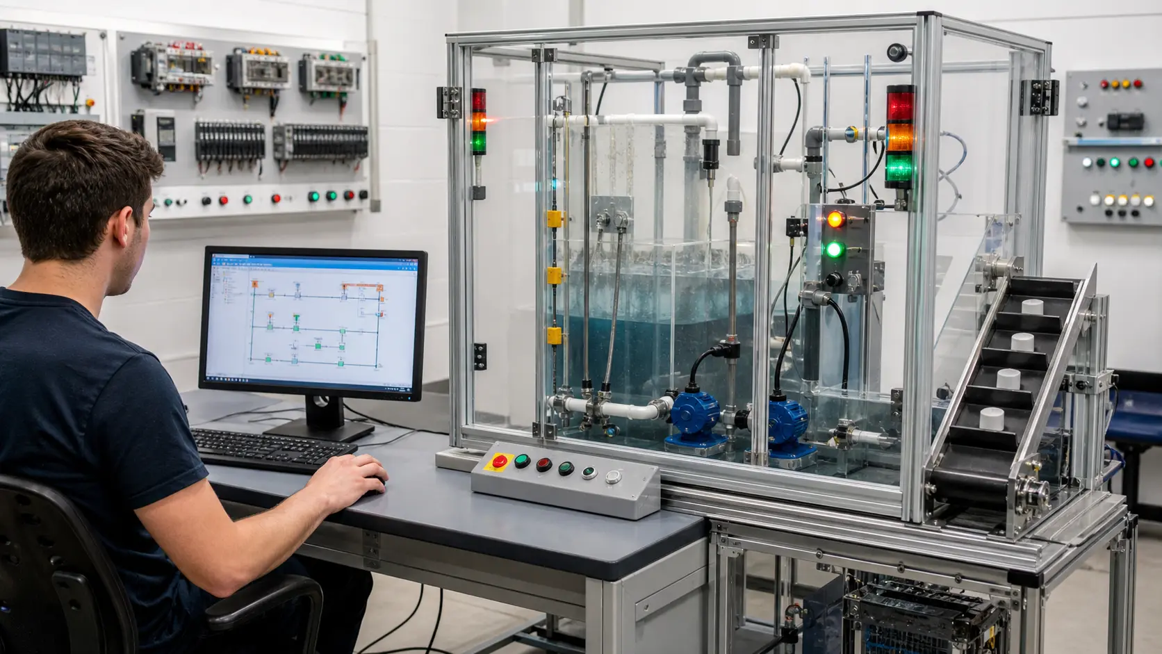
a browser PLC workstation connected to a guarded pump, level and conveyor training rig for repeatable control cases while studying first PLC input, rung and output behavior
System map / 02

NODE 01observable

Scenario setup

Initial switch state, input tag, contact instruction, rung truth, lamp output, scan assumption and stopping state.

NODE 02observable

I/O and state map

User switch through simulated input, program evaluation, output image, lamp model and visible feedback.

NODE 03observable

Normal run

Switch off and on repeatedly with the input, rung, output and lamp matching the written truth table.

NODE 04observable

Boundary run

Startup, rapid toggle, inverted contact, output written twice, refresh, reset and mismatched tag.

NODE 05observable

Injected fault

An input, polarity, rung-truth, output-owner, mapping, scan or visualization misunderstanding.

NODE 06observable

Target check

The same behavior rebuilt in the target PLC with compatible I/O wiring and measured field response.

Answer surface / 07

What is the simplest PLC program?

One Boolean input controlling one Boolean output is a useful first program because the entire truth and signal path can be predicted.

What should I learn after switch-to-light logic?

Add normally closed truth, start-stop seal-in logic, explicit stop priority, timers, counters and independent machine feedback.

Real plc ladder logic basics footage

See this exact skill in the working simulator.

Watch the real browser product respond to the task on this page, then try the same practical workflow yourself. No slides, concept mockups, install, or credit card.

Try this in the browser
Your First PLC Program — Switch Turns On a Light