Process Control Simulator for PID, Analog Signals and PLC Logic
Connect controller logic to a dynamic process, apply a known disturbance and prove the response. Practise temperature PID, 4–20 mA scaling, tank control, batch sequencing, dosing, alarms and duty/standby pumps in a browser.
Free account, no credit card, no expiry. The scenario catalog requires an account; availability varies by plan and entitlement. This is learning and prototyping software, not a production controller or process-design package.
Join 14300+ learners practicing PLC programming
Direct answer
What this simulator controls—and what it does not
A PLC process-control simulator is useful when the question is, “Will this control program make the simulated process behave correctly?” It should expose a process variable, a manipulated output, disturbances, sequence state and objective pass criteria. It is not automatically a chemical process simulator, an operator-training simulator, a vendor controller emulator or a production digital twin. Those categories solve different engineering problems and demand different fidelity.
| Tool category | The question it should answer | Typical model depth | Fit here |
|---|---|---|---|
| PLC process-control practice | Does my logic scale, sequence, alarm and regulate a bounded training process? | Signals, logic scan, simple plant dynamics, disturbances and grading | Primary use |
| Chemical flowsheet simulator | Do material, energy, equilibrium and equipment calculations support the process design? | Thermodynamics, reactions, streams and equipment models | Not provided |
| Operator-training simulator | Can operators rehearse a specific plant and control-room procedure? | Plant-specific DCS, graphics, narratives and high-fidelity dynamics | Not provided |
| Production digital twin | Can governed engineering and operational data reproduce or predict this asset? | Asset-specific data, integration, calibration and lifecycle controls | Not provided |
| Vendor PLC emulator | How does this project execute on a specific controller family and toolchain? | Vendor instructions, firmware behavior, project files and diagnostics | Use alongside this product |
Six views of the learning method
See the complete control-and-evidence chain
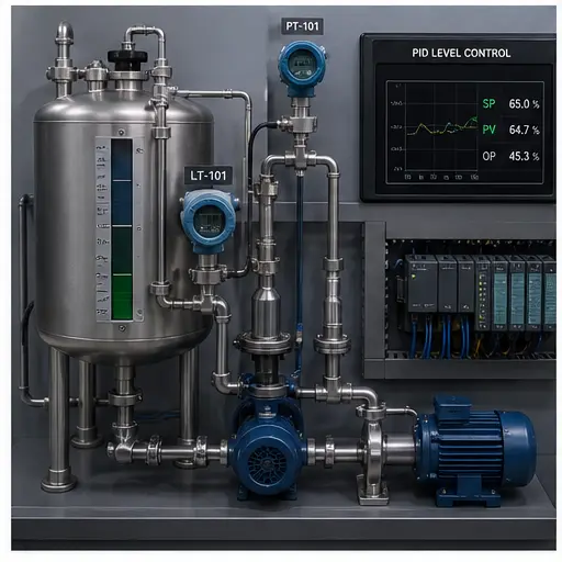
These original technical panels explain how the learning path connects PLC logic, analog signals, dynamic response, process scenarios, troubleshooting evidence and a repeatable proof protocol. Open the linked scenarios where available, then compare the illustration with the product behavior.


Capability evidence
Process scenarios you can verify in the catalog
The table below is derived from the product’s source-catalogued scenario definitions, reviewed for this page on 31 August 2026. “Evidence” means the behavior the scenario grader expects—not a claim that the exercise reproduces every physical or vendor-specific detail. Sign in to play catalog records; visibility varies by tier and entitlement.
| Scenario | Control skill | Observable evidence | Open |
|---|---|---|---|
| PID temperature | Closed-loop PID, limits, timebase, disturbance and independent alarm latch | Settles within ±3 °C of 60 °C inside 120 s; stays below 70 °C; recovers after a 60 s fan disturbance; alarm remains latched | View lab |
| Dual-pump tank fill | Level hysteresis, lead/lag alternation, high-high trip and emergency drain | Lead pump starts at low level, stops at high, alternates next cycle, and both pumps trip on high-high | View lab |
| Pressure scaling | Raw analog input to engineering units with range and quality reasoning | Known raw points map to expected pressure and invalid signal behavior is handled | View lab |
| Tank level alarms | Analog thresholds, alarm bands and state handling | Level regions produce the expected low, normal, high and fault indications | View lab |
| Temperature setpoint | Deadband and two-position control around a process target | Heating behavior changes at the defined band without rapid threshold chatter | View lab |
| Valve output | Proportional calculation and bounded command output | Command follows the intended relationship and remains within usable output limits | View lab |
| Batch mixer | State machine, timed mixing, draining, optional CIP and stop fault | Only the output for the active phase runs; timers and physical conditions gate every transition | View lab |
| Chemical dosing | Permissives, P-only controller output and low-tank trip | Pump runs only with flow and enable; speed changes with level; low tank stops dosing | View lab |
| Lift station | Duty/standby alternation, thermal-fault handoff and alarm behavior | Duty swaps after a completed cycle and standby takes over when the duty pump trips | View lab |
The catalog currently records 171 source definitions. That number is a catalog fact, not a promise that every record is public, free or visible to every account. The source registry and seeder define 170 scenario records marked published, plus the separate sandbox definition. The number visible to a visitor can be lower because access depends on account state, tier, entitlement and staged feature rollout. The no-account /try experience is a guided first program; catalog scenarios use an account.
Worked PID example
From ambient temperature to a defensible pass decision
The temperature lab begins near 20 °C and asks the controller to reach a 60 °C setpoint. The function block is called once per scan with a 50 ms timebase and a bounded 0–100% output. The scenario suggests conservative starting values around Kp 2.0, Ki 0.3 and Kd 0.5 for its own canonical thermal model. Those values are exercise-specific starting points, not universal tuning constants for a real vessel.
The learning value comes from predicting what the trends should do, not copying three gains. Proportional action responds to present error, integral action accumulates persistent error, and derivative action responds to the rate of change under the block’s implemented form. Output limiting matters because a simulated heater cannot command below 0% or above 100%. The declared timebase matters because integral and derivative calculations depend on elapsed time.
Inspect the graded PID scenario| Test | Scenario criterion | What a failure teaches |
|---|---|---|
| Setpoint convergence | Reach 60 °C and settle within ±3 °C inside 120 s | Direction, enable, scaling or tuning may be wrong |
| Peak overshoot | Do not rise above 70 °C during the transient | The response may be too aggressive or poorly damped |
| Disturbance rejection | After the cooling fan runs for 60 s, remain within ±3 °C | The loop may lack recovery authority or integral action |
| Ready indication | Remain within ±1 °C for 10 continuous seconds | A momentary crossing is not the same as stable control |
| Alarm memory | A TEMP_HIGH event latches ALARM until a valid reset condition | Protective indication must not disappear with the initiating pulse |
Analog inputs before algorithms
A 4–20 mA value needs identity, quality and scaling
A displayed “63.4%” can look credible while being wrong. The transmitter may have a different configured range, the input card may represent raw counts differently, the signal may be below its live-zero region, or the program may use the wrong engineering limits. A simulator should teach you to preserve the evidence chain instead of treating one REAL tag as truth.
1. Define the measurement
Record the physical quantity, engineering units, lower range value and upper range value. “Pressure” is incomplete; “0–10 bar gauge” is testable.
2. Confirm the raw representation
Use the exact analog-module documentation for the configured mode. Different modules and vendors may expose different counts, status bits and under-range or over-range behavior.
3. Validate signal quality
Separate a valid low process value from an open circuit, underrange, overrange, stale value or disabled channel. Decide what the control program does when quality is bad.
4. Scale with known points
For a linear range, map known raw endpoints into engineering endpoints, then test at least one interior point. Clamp only when the specification says to; blind clamping can hide a failed signal.
5. Filter deliberately
A filter can reduce noise but also adds lag. Record the filter constant and test whether alarm and control response remain acceptable during a real change.
6. Keep alarms separate
Low, high and deviation alarms need documented purpose, setpoint, deadband, delay, priority and operator response. A threshold alone is not an alarm philosophy.
Portable learning rule
Keep signal conversion in a named boundary, expose a quality state, and let the control strategy consume engineering units only after validation. The exact raw counts and status semantics are vendor-specific; the separation of concerns is transferable.
From loop to operating sequence
Continuous control, discrete interlocks and batch state belong in one test story
A real process application rarely consists of a PID block floating by itself. The loop may regulate temperature or level, but a permissive decides whether the actuator can run, a sequence decides when the loop is active, a mode handler decides who owns the output, and alarms tell an operator when intervention is required. Training each idea separately is useful at first; competence appears when they work together without hidden ownership conflicts.
Consider a heated batch vessel. A batch state requests heating only after the correct ingredients are present and the agitator has proven running. The PID controller calculates heater demand from setpoint and measured temperature. Output conditioning clamps that demand and may apply an approved rate limit. An independent high-temperature condition inhibits heat and raises an alarm. Stop, abort and equipment-fault paths must return every commanded valve, pump and heater to its defined state. The important design question is not “Which rung turns on the heater?” but “Which layer owns the command in every mode and abnormal condition?”
| Control layer | Owns | Example decision | Negative test |
|---|---|---|---|
| Measurement boundary | Raw/status conversion and engineering value | Publish temperature only when the configured input is valid | Break the simulated signal and confirm bad quality is not treated as a genuine cold vessel |
| Operating mode | Manual, automatic, stopped and maintenance ownership | Automatic PID may command heat only while Auto is selected | Change modes and verify there is no output bump or stale command where the exercise supports the transition |
| Sequence state | When equipment and loops are requested | Enable heat in Mix/Heat, disable it in Fill, Drain, Abort and Idle | Abort from every active state and verify outputs return to the specified state |
| Permissive/interlock | Conditions required to act or continue | Require minimum level and proven agitation before heating | Remove one permissive while active and verify the defined trip, hold or controlled-stop behavior |
| Regulatory control | The bounded manipulated output needed to reduce error | Calculate 0–100% heater demand from SP, PV and configured gains | Drive error high enough to expose saturation and test recovery after saturation |
| Alarm handling | Operator notification and retained abnormal state | Raise a meaningful high-temperature alarm that requires a timely response | Pulse the initiating condition and verify the documented latch and acknowledgement behavior |
| Final command | One auditable write to the actuator request | Combine owner, request, interlock and limit into one heater command | Search for duplicate writes and prove stop/abort wins under every tested ordering |
Write the control narrative before the rungs
A compact control narrative states the trigger, preconditions, action, success feedback, timeout, abnormal response, reset rule and restart rule for each behavior. For a fill valve, “open on Start” is not enough. A testable narrative could say that Auto and Batch Fill request the valve only when the vessel is not high-high, the downstream route is available and no abort is active; a valve-open feedback must arrive within the allowed time; failure raises a named alarm and prevents the next phase; acknowledgement does not restart the phase automatically.
That paragraph creates multiple test cases before implementation begins. It also exposes decisions that code can otherwise hide: whether loss of a permissive trips immediately or completes a controlled stop, whether a fault is latched, and whether recovery resumes or waits for a new command. The simulator is most valuable when the learner turns those sentences into observable cases rather than merely obtaining a green compile indicator.
Separate an alarm from an event or status
A pump-running indication, a sequence transition and an operator alarm are not interchangeable. A useful alarm represents an abnormal condition that requires a timely response. It needs a documented cause, consequence, operator action, priority, setpoint, deadband or delay where appropriate, acknowledgement behavior and return-to-normal behavior. The ISA-18 series treats alarm management as a lifecycle, including rationalization, design, operation, monitoring, maintenance and change.
A learning scenario can demonstrate threshold logic, delay, latching and acknowledgement, but it cannot complete a site alarm philosophy or prove that a priority is appropriate. Use the exercise to practise deterministic behavior: inject the initiating condition, record the activation time, remove the condition, acknowledge in the wrong and right states, and prove the alarm does not silently disappear. Keep safety functions and independent protection outside the ordinary control alarm unless the approved design explicitly defines otherwise.
Twelve acceptance questions for any process scenario
These questions work as a reusable review sheet for a tank, temperature loop, batch, dosing skid or pumping station. Not every training model exposes every function, but unanswered questions should become explicit limitations rather than assumptions.
PC-01 Normal start
Do all required permissives produce the intended first state and only the intended outputs?
PC-02 Normal stop
Does Stop return every actuator request, timer and sequence state to the documented condition?
PC-03 Boundary values
What happens exactly at low, high, setpoint, deadband and clamp boundaries?
PC-04 Signal failure
Can the program distinguish invalid quality from a valid process value near the bottom of range?
PC-05 Output saturation
Does the controller remain understandable when its command reaches a minimum or maximum?
PC-06 Disturbance
Does a repeatable load change produce recovery within the predeclared band and time?
PC-07 Interlock loss
Does removing each permissive cause the specified trip, hold or controlled stop?
PC-08 Feedback timeout
Does missing actuator feedback stop sequence progression and expose the correct diagnostic?
PC-09 Alarm lifecycle
Do activation, acknowledgement, return to normal and reset follow the written rule?
PC-10 Mode ownership
Can only one source own the final command, including during transitions and restart?
PC-11 Power/restart assumption
Are retained states and restart behavior explicit rather than inherited accidentally?
PC-12 Post-fix regression
After clearing the injected fault, do normal, stop, boundary and remaining fault cases still pass?
Troubleshooting method
Do not tune around a broken process
When a loop will not hold setpoint, changing gains is only one possible action. A systematic investigation starts with the symptom and safe operating state, then follows the signal and energy path. This prevents a plausible trend or blinking input from becoming the whole diagnosis.
| Evidence zone | Question | Simulation test | Real-system caution |
|---|---|---|---|
| Symptom and safe state | What exactly failed, when did it start, and what must remain de-energized? | Write the expected safe outputs before injecting a fault | Apply site isolation and operating procedures before measurements or movement |
| Field signal | Did the transmitter or switch respond to the physical change? | Change the simulated process and observe the source signal | Use approved test points, calibrated tools and qualified-person rules |
| Input and quality | Did the module/tag receive a valid value with valid status? | Inject under-range or fault state separately from a legitimate low value | Check configuration, wiring, supply and diagnostics against the module manual |
| PLC logic | Which permissive, mode, state or calculation blocks the command? | Trace only the affected path and record the first false or invalid condition | Online edits and forces require authorization, impact review and removal verification |
| Actuator command | Is the output limited, interlocked or saturated? | Hold a disturbance and observe the requested CV versus its bounds | An energized output tag does not prove valve travel, motor torque or final-element health |
| Physical process | Does the plant respond in the correct direction and at a believable rate? | Compare the response with the scenario model and defined acceptance band | Real dynamics, delays, nonlinearities and hazards can exceed the training model |
| Post-fix verification | Did the root cause clear without damaging another mode or protective function? | Repeat normal, boundary, disturbance and reset cases | Restore temporary states and complete controlled acceptance records |
Build the diagnostic habit with known faults
The dedicated troubleshooting path covers wiring, logic, runtime and scan-order evidence, then connects each simulated symptom to a repeatable isolation method.
Dated hands-on audit
Process-control capability protocol — 31 August 2026
We inspected the current scenario definitions, public product facts and access rules before publishing this page. The protocol below turns that inspection into a reproducible product check. It is intentionally narrower than a production factory-acceptance test: it validates published learning behavior, not a real plant design or safety claim.
- 1
Record preconditions
Use a supported modern browser, note the account tier, open the named catalog scenario, reset prior state and capture the scenario revision or review date available to the tester.
- 2
Predict the response
Before running, write the expected starting output, direction of PV movement, alarm state, limiting condition and pass band. This separates understanding from post-hoc explanation.
- 3
Run the nominal case
Exercise start, normal regulation or sequence transitions, stop and reset. Compare observed outputs and process state with the scenario’s named cases.
- 4
Apply one controlled disturbance
Use the provided fan, sensor fault, thermal trip, high-high level or process condition. Change one cause at a time so the observed response remains attributable.
- 5
Inspect evidence at every layer
Record field-model state, raw/engineering signal, quality or fault state, PLC condition, command output and process response. A pass should not rely on one lamp.
- 6
Verify recovery and retained state
Remove the disturbance, check recovery band and timing, confirm alarm acknowledgement rules, and ensure stop or reset does not create an unintended restart.
- 7
Document limitations
Record missing vendor behavior, model simplifications, unavailable features and account restrictions. Do not generalize a training result into production approval.
| Record field | Example | Why retain it |
|---|---|---|
| Scenario and access | PID temperature; signed-in catalog; entitlement noted | Makes the result reproducible and avoids implying anonymous access |
| Configuration | SP 60 °C; Kp 2.0; Ki 0.3; Kd 0.5; DT 50 ms; output 0–100% | Connects the response to a complete controller state |
| Disturbance | Cooling fan enabled for 60 s after steady state | Defines the cause and timing instead of saying “it recovered” |
| Observed measures | Peak PV, time into band, end-of-disturbance error, maximum CV | Supports a pass decision with inspectable evidence |
| Decision and exception | Pass/fail per scenario; browser and any anomaly recorded | Keeps marketing, product QA and learning evidence separate |
Best-fit decision
Who should use this—and who should choose another tool
Strong fit
PLC student
Use guided scenarios to connect ladder or Structured Text to changing process values, timed sequences and graded outcomes.
Strong fit
Maintenance technician
Rehearse signal-to-process troubleshooting and repeat faults without taking a production asset out of service.
Good companion
Junior controls engineer
Prototype transferable control patterns here, then verify the final implementation in the actual vendor toolchain and target hardware.
Strong fit
Instructor or training team
Assign repeatable labs, compare outcomes and reserve physical benches for wiring, measurement and controller-specific work.
Choose another category
Chemical process designer
Use validated flowsheet and equipment-design software for mass balance, energy balance, equilibrium, kinetics and sizing.
Choose specialist procurement
Plant OTS or digital-twin buyer
Specify plant fidelity, DCS integration, model validation, instructor station, cyber controls, lifecycle support and acceptance evidence.
Standards and source boundary
Technical references used to keep the claims bounded
The simulator implements its own educational runtime and scenario models. The references below define relevant industrial concepts or vendor examples; they do not certify this product. Current controller projects must be checked against the exact vendor, firmware, module and site requirements in use.
| Primary source | Used for | Boundary |
|---|---|---|
| IEC 61131-3:2025 | Current syntax and semantics framework for PLC languages including ST, LD and FBD | A standard language framework does not make every vendor instruction or runtime identical |
| Rockwell PIDE documentation | Example of a vendor process-control instruction with setpoint, PV and enhanced PID behavior | This simulator’s PID block is not a claim of complete PIDE compatibility |
| Siemens PID control manual | Example of PID_Compact technology objects, configuration and controller-specific commissioning | Training concepts transfer, but Siemens project behavior must be verified in Siemens tools |
| Rockwell PointMax Analog I/O manual | Current vendor example of 4–20 mA underrange, overrange, open-wire and field-power diagnostics | Thresholds and diagnostic tags belong to the exact module and configuration, not to every analog input |
| Siemens S7-1200 system manual | Current controller and analog-module ranges, diagnostics, conversion and wiring examples | Use the exact order number, revision and channel mode when turning current into controller data |
| ISA-18 series | Alarm management lifecycle, rationalization, operation, monitoring and change | A simulated threshold exercise is not a completed alarm-management lifecycle |
| IEC 62682:2022 | Alarm-system management for continuous, batch and discrete process facilities | The standard addresses an operational lifecycle beyond controller threshold logic |
| NIST SP 800-82 Rev. 3 | Operational technology security context and the special performance, reliability and safety constraints of OT | A public browser lab must not be connected to production control networks |
| OSHA 29 CFR 1910.147 | US hazardous-energy control requirements relevant to real servicing and maintenance | Browser simulation does not teach or replace site-specific lockout/tagout authorization and practice |
| IEC 61511-1:2016 | Lifecycle requirements for safety instrumented systems in the process industry sector | Ordinary browser control exercises do not implement or validate a safety lifecycle or safety integrity level |
Start with evidence, not a sales promise
Create a free account and inspect the process labs yourself
The free tier requires no credit card and does not expire. Basic is currently $12/month and Pro $29/month; use the pricing page for current eligibility and plan details. Begin with the PID scenario, compare the actual interface with this audit, and upgrade only if the available practice fits your learning goal.
Want a no-account preview of the general PLC workflow first? Run the guided first program. It is not the PID process lab, but it shows the editor and scan-based learning model before signup.