The master control relay (MCR) instruction is a software fence that switches off a zone of ladder rungs at once. You place one MCR at the start of the zone and a second MCR at the end; when the start MCR is false, every non-retentive output between the two is de-energised in a single scan. It is a program-structure tool — not a safety device, and never a replacement for a hardwired E-stop or safety relay.
That distinction is the most important thing on this page, so it is worth saying again before we go any further: the MCR instruction runs inside the CPU. If the CPU, its firmware, or its output card fails, the instruction fails with it. A real machine-safety stop must remove power through hardwired contacts that do not depend on the processor. The MCR is for organizing and disabling logic, not for protecting people.
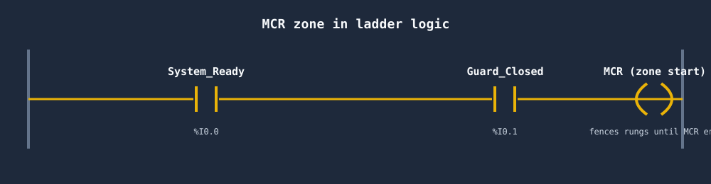
What an MCR zone looks like
An MCR comes in a pair. The first MCR instruction begins a fenced zone; the second MCR (with no preceding contacts) ends it. Whatever rungs sit between them are controlled as a group by the conditions on the first MCR.
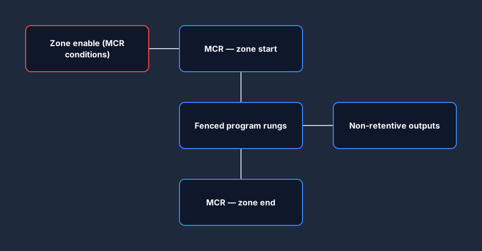
- Zone start —
MCRpreceded by contacts. When those contacts are true the zone runs normally. When they are false the zone is fenced off. - Fenced rungs — your normal logic. Outputs here behave as usual only while the zone is enabled.
- Zone end — a standalone
MCRwith nothing in front of it. It marks where the fence closes.
How the MCR controls a section of the program
Think of the MCR zone as a switch in front of a block of your program. When the zone is enabled the rungs inside are scanned and act normally. When the zone is disabled the rungs are still scanned, but every non-retentive output inside is forced off.
This is why an MCR is so handy for grouping logic: one set of enable conditions — a "system ready" bit, a mode selector, a guard-closed interlock — can disable an entire subsystem of outputs without you wiring that condition into every single rung.
What happens when the zone goes false
The moment the start MCR goes false, all non-retentive outputs in the zone drop on that scan. The timing diagram below shows three outputs falling together the instant the zone-enable signal goes low.
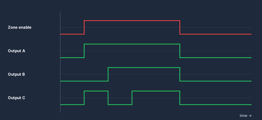
There is a critical exception you must remember: retentive instructions hold their state. A latch (OTL/SET), a retentive timer (RTO), or a counter accumulator inside the zone does not reset when the zone goes false — it simply stops being updated. When the zone re-enables, those instructions resume from where they were. If you assume an MCR "clears everything", a latched output can come straight back on, which is exactly the kind of surprise that hurts people on a real machine. Plan your retentive instructions deliberately, or keep them outside the zone.
MCR instruction vs a hardwired E-stop
This is the heart of the safety message. An MCR and a hardwired emergency-stop circuit can both "stop the outputs", but they are not interchangeable.
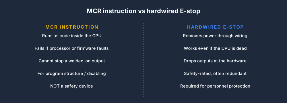
The MCR is software running on a general-purpose CPU. A hardwired E-stop drops power through dedicated, often redundant, safety-rated contacts that operate whether or not the processor is alive. Code can hang; an output transistor can weld on; firmware can fault. None of those failures will release a properly designed hardwired safety circuit, but all of them can defeat an MCR. Use the MCR for program structure and operational disabling. Use a hardwired, safety-rated circuit — sized per the machine's risk assessment — for emergency stop and personnel protection.
A safe-use checklist for the MCR instruction
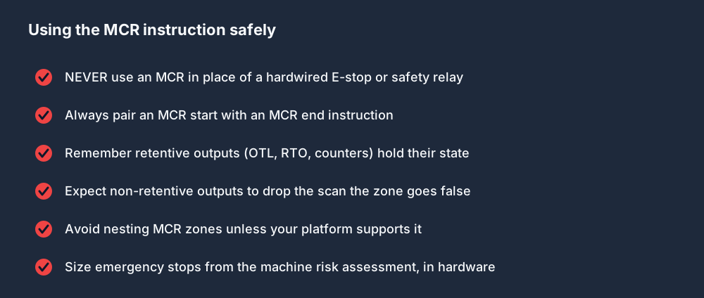
Read the first item on that list as non-negotiable: the MCR never replaces hardwired safety. Everything else — pairing your instructions, watching retentive outputs, and not nesting zones unless your platform explicitly supports it — keeps the logic predictable, but only the hardware keeps people safe.
MCR vs JMP vs AFI
Beginners often confuse the MCR with the jump (JMP) instruction and the always-false instruction (AFI / unconditional disable). They all "turn logic off", but they behave very differently.
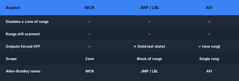
- MCR still scans the fenced rungs but forces their non-retentive outputs off. It is the right tool when you want a block of outputs to drop together.
- JMP/LBL skips rungs entirely — they are not scanned, so their outputs hold their last state rather than turning off. That difference catches people out constantly.
- AFI simply makes a single rung evaluate as false; it disables one rung, not a zone.
If your goal is "make these outputs go off", reach for the MCR — not the jump, which can leave outputs frozen on.
Practice the MCR in your browser
The fastest way to see an MCR zone behave — including how a latch survives the zone going false — is to wire it up and toggle the enable yourself. You can do exactly that in the free browser PLC simulator, and switch the ladder logic editor between IEC, Allen-Bradley and Siemens dialects to see how each one names the instruction. While you are there, the related seal-in / latching rung guide explains exactly why a latched output inside an MCR zone can come back on.
FAQ
What is a master control relay in a PLC? It is an instruction that fences off a zone of ladder rungs. You place an MCR at the start and end of the zone; when the start MCR's conditions are false, every non-retentive output inside the zone is de-energised in that scan.
Is an MCR instruction a safety device? No. The MCR runs in the CPU and fails if the processor, firmware or output hardware fails. It is never a substitute for a hardwired, safety-rated E-stop or safety relay. Emergency stop and personnel protection must be implemented in hardware per the machine's risk assessment.
What is the difference between MCR and JMP in a PLC? An MCR still scans the fenced rungs but forces their non-retentive outputs off. A JMP skips the rungs entirely, so they are not scanned and their outputs hold their last state instead of turning off.
Do retentive outputs reset inside an MCR zone? No. Latches (OTL/SET), retentive timers (RTO) and counters hold their state when the zone goes false — they just stop updating. They can resume or come back on when the zone is re-enabled, so plan them carefully.