A PLC counter keeps a running tally of events. The three you will meet everywhere are CTU (count up), CTD (count down) and CTUD (count up/down). They share the same handful of parameters — a count input, a reset, a preset value and a current value — and differ only in whether the current value climbs, falls, or does both, and when the done bit turns on. Master those three and counting parts, batches, strokes and cycles on a real machine becomes routine.
This guide walks through each counter with a timing diagram, shows the ladder logic, and lists the names each vendor uses so you are not lost when you move from Allen-Bradley to Siemens or Mitsubishi.
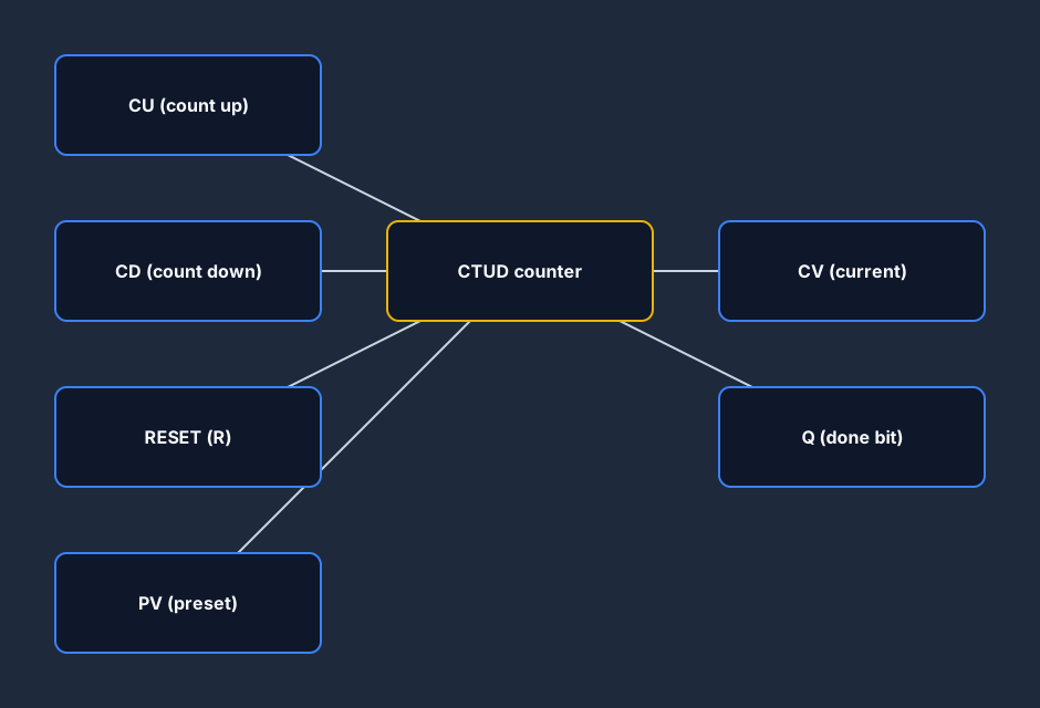
The parts of every counter
An IEC 61131-3 counter is a function block. The CTUD has the full set; CTU and CTD use a subset:
- CU — count-up input. Each rising edge adds one to the current value.
- CD — count-down input. Each rising edge subtracts one (CTD and CTUD).
- RESET / R — clears the current value back to zero (CTU and CTUD).
- LOAD / LD — presets the current value to PV (CTD and CTUD).
- PV — the preset value you are counting to.
- CV — the current value, the running count itself.
- Q / QU / QD — the done bit your logic actually reads.
The single most common beginner bug is counting on a level instead of an edge: a counter only increments on the rising edge of CU, not for every scan the contact stays closed. Always drive downstream logic from the done bit Q, never from the raw count input.
CTU — the up-counter
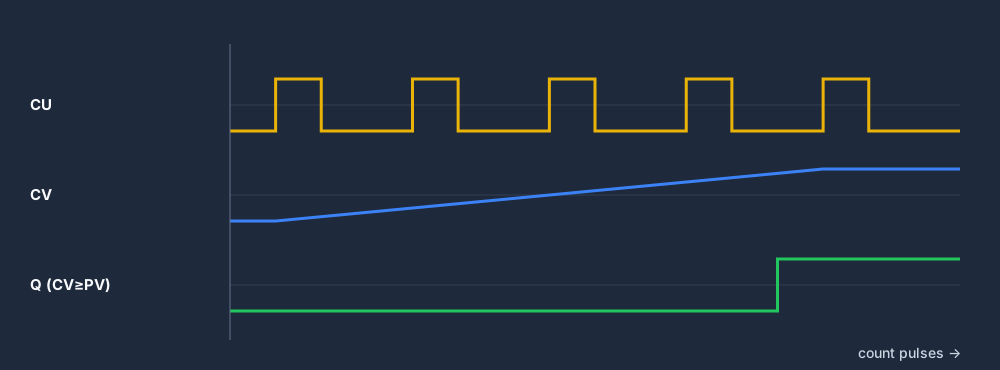
A CTU counts up. Each rising edge on CU adds one to CV; once CV reaches PV, Q turns on and stays on. CV keeps climbing past PV (it does not stop), so Q remains true until you pulse RESET to clear CV back to zero.
Use a CTU whenever you want to act after N events: package twelve bottles into a case, dispense a batch after a set number of strokes, or flag maintenance after a fixed cycle count.
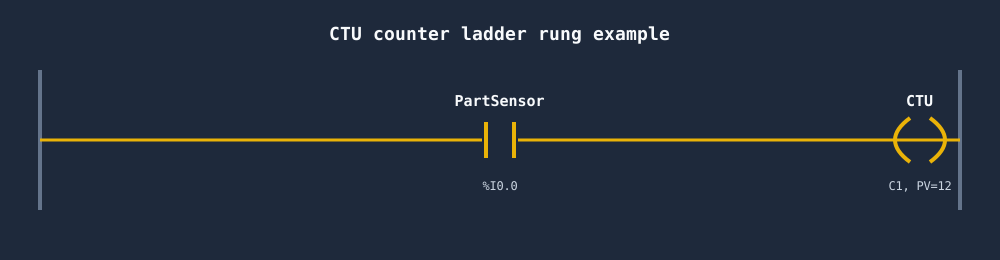
Here is the classic rung: a part sensor drives CU, so every part that breaks the beam adds one to the count.
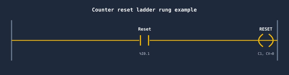
And you always need a way to start over — a separate rung pulses RESET to clear the count for the next batch.
CTD — the down-counter
A CTD counts down from a preset. You first pulse LOAD to set CV equal to PV; then each rising edge on CD subtracts one. When CV reaches zero, Q turns on. CTD is the natural fit when you want to know how many are left rather than how many you have done.
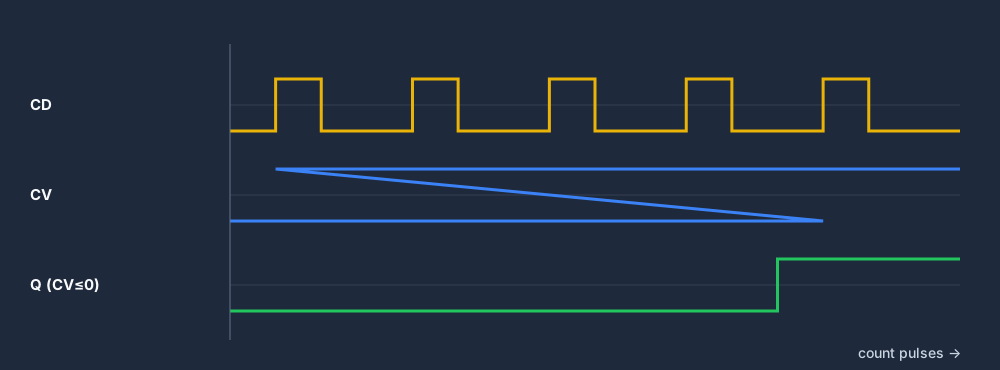
Reach for a CTD for "remaining" logic: load 50 labels and stop the line when the reel is empty, or count a fixed allotment of parts down to zero before requesting a refill.
CTUD — the up/down counter
A CTUD does both. CU adds, CD subtracts, RESET forces CV to zero, and LOAD forces CV to PV. It exposes two done bits: QU turns on when CV ≥ PV, and QD turns on when CV ≤ 0. One block tracks a net total that can rise and fall.
CTUD is built for occupancy problems: count cars into and out of a parking deck and light "FULL" when QU sets, or track items in a buffer between two machines so an upstream feeder pauses when QU trips and resumes once parts drain out.
CTU vs CTD vs CTUD at a glance
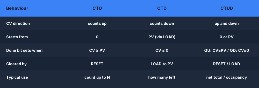
If you only remember one thing: CTU counts up to PV, CTD counts down to zero, CTUD does both with two done bits.
Which counter should you use?
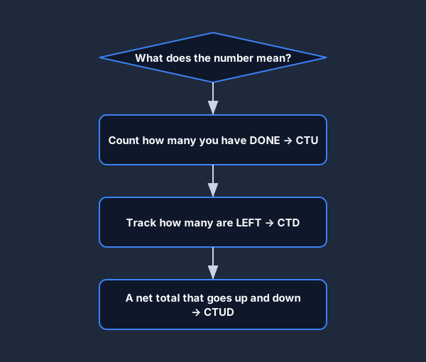
Ask what the number means: how many you have done (CTU), how many are left (CTD), or a net total that goes up and down (CTUD). That single question picks the counter almost every time.
Counter names in each PLC dialect
The behavior is standard, but the names are not. Learn the IEC 61131-3 names and you can map everything else.
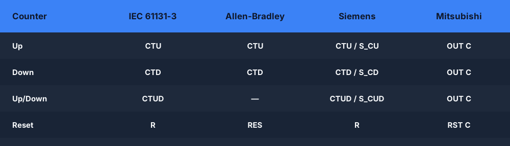
Note that Allen-Bradley splits the up/down counter into two separate instructions, CTU and CTD, that share one counter tag and structure (with .ACC, .PRE, .DN members) and are cleared with a RES instruction — there is no single CTUD block. Siemens S7 offers both the IEC CTU/CTD/CTUD blocks and the legacy S_CU/S_CD/S_CUD counters. Mitsubishi uses simple OUT C / RST C counting on device addresses, with dedicated high-speed counters for fast pulses.
Common counter mistakes
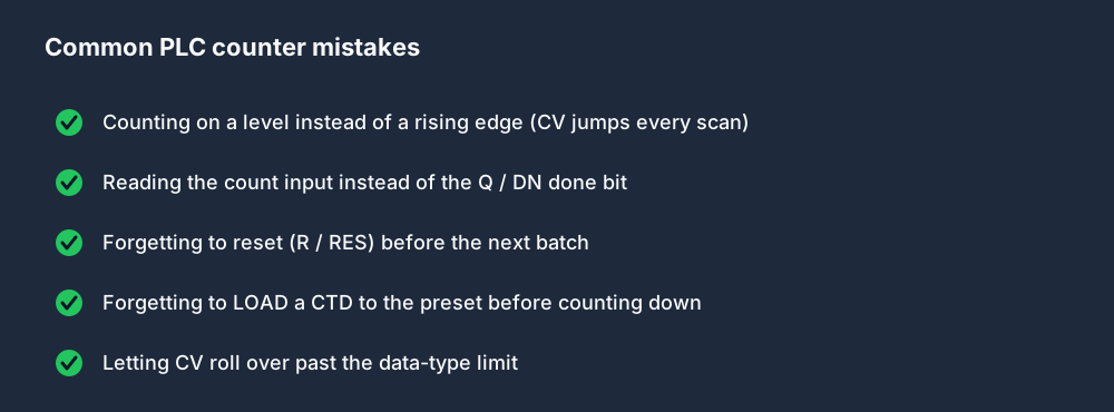
Most counter "faults" on a real machine are one of these — and almost all trace back to the scan cycle: a counter that sees a level instead of an edge will rack up one count per scan and overshoot PV in milliseconds.
Practice counters in your browser
The fastest way to make counters stick is to wire one up and watch CV climb on every sensor pulse. You can do exactly that — CTU, CTD, CTUD, TON/TOF/TP timers and edge detection — in the free browser PLC simulator; switch the ladder logic editor between IEC, Allen-Bradley and Siemens dialects to see the naming differences for yourself.
FAQ
What is the difference between CTU and CTD? A CTU counts up from zero and turns its done bit on when the current value reaches the preset (CV ≥ PV). A CTD counts down from the preset and turns its done bit on when the current value reaches zero (CV ≤ 0).
What does CTUD do in a PLC? A CTUD is an up/down counter: the CU input adds one and the CD input subtracts one on each rising edge. It has two done bits — QU (CV ≥ PV) and QD (CV ≤ 0) — so it can track a net total that rises and falls.
Do PLC counters count on every scan? No. A counter increments only on the rising edge of its count input, not for every scan the contact stays true. If yours counts too fast, you are triggering it on a level instead of an edge.
How do you reset a PLC counter? Pulse the RESET (R) input to clear the current value to zero. In Allen-Bradley you use a separate RES instruction that targets the counter tag.
What are CU, CD, PV and CV on a PLC counter? CU is the count-up input, CD is the count-down input, PV is the preset value you are counting to, and CV is the current value — the running count itself.