A PLC state machine breaks a machine's behavior into a small set of named steps—such as Idle, Fill, Drain and Done—and moves between them only when defined transition conditions become true. A simple sequential machine normally has one active step; Grafcet and Sequential Function Chart (SFC) can also represent deliberately parallel active branches. Grafcet is the graphical method for describing step-and-transition sequences, while SFC is the IEC 61131-3 structuring language built around steps, transitions and actions. Once you think in explicit states and transitions, even a complicated batch sequence becomes a reviewable model you can implement in ladder, Structured Text or SFC.
This guide shows you the state-machine mindset, the Grafcet/SFC structure, two ways to code it on a real PLC, and the design steps that keep your sequences clean.

What is a state machine on a PLC?
Most machines do things in order. A bottle filler waits for a bottle, fills it, lets it settle, caps it, then ejects it — always in that sequence, never out of order. A state machine captures exactly that: a finite list of states (steps), and the rules for moving between them.
For a simple mutually exclusive sequence, the key idea is that exactly one normal step is active at any moment. That rule makes the machine easier to debug than free-form logic: at any instant you can ask “which step are we in?” and receive one clear answer. When the design uses an intentional parallel split, each active branch still has explicit steps and a defined condition for rejoining.
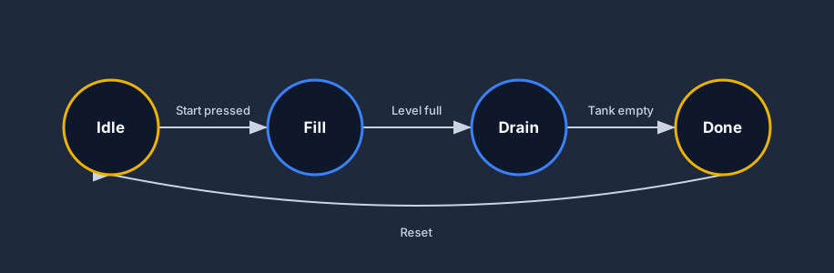
Each arrow is a transition with a condition. You leave Idle for Fill when a Start button is pressed; you leave Fill for Drain when the level sensor reports full; you leave Drain for Done when the tank is empty. Nothing happens "by accident" because every move requires its condition to be true.
Grafcet and the Sequential Function Chart (SFC)
Grafcet (from the French GRAphe Fonctionnel de Commande Étapes/Transitions) is the formal way to draw a sequence as alternating steps and transitions. The international standard built on it is the Sequential Function Chart (SFC) — one of the five languages in IEC 61131-3, alongside ladder, Structured Text, function block and instruction list.
An SFC reads top to bottom. Each step can carry actions (the outputs to drive while that step is active), and each transition carries a condition that must be true before the active step passes the token down to the next step.
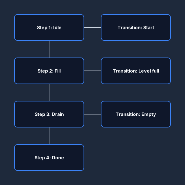
The beauty of SFC is that the order of operations is visible in the diagram itself. You are no longer hunting through dozens of rungs trying to reconstruct what runs when — the chart is the sequence.
State machine vs spaghetti logic
If you have ever inherited a program where the same output is set on six different rungs under tangled interlock conditions, you have met spaghetti logic. It "works" until you need to change it, and then every edit risks breaking a hidden case.
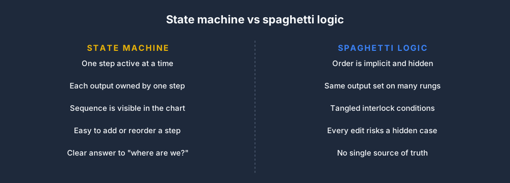
A state machine forces discipline: one output is owned by the step that needs it, and a step only runs when the sequence has legitimately reached it. The result is logic that a colleague — or you, six months later — can actually follow.
How to design a state machine
You do not start by writing code. You start by listing the steps a person would do by hand, then naming the event that ends each one.
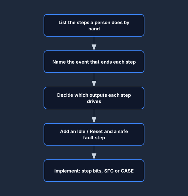
Work through it on paper or in a Grafcet diagram first. List every step, write the transition condition that exits it, and decide which outputs each step drives. By the time you reach the keyboard, the program almost writes itself.
Implementing a state machine in ladder logic
You do not need the SFC language to use the SFC idea. The most portable approach across Allen-Bradley, Siemens and any other vendor is a set of step bits — one boolean per step — driven by Set and Reset (latch/unlatch) coils.
When a transition fires, you Set the next step bit and Reset the current one. Because exactly one step bit is on, your output logic just reads the relevant step bit.
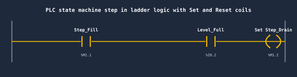
The pattern for each transition is one rung: "if I am in step N and the transition condition is true, then advance to step N+1." Holding a step active is exactly the same seal-in / latch pattern you already use for motor start-stop circuits — a state machine is really just a chain of well-organised seal-in rungs.
Ladder vs SFC vs CASE in Structured Text
There are three common ways to build the same state machine, and the best choice depends on your toolchain and team.
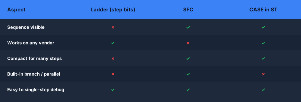
In Structured Text the state machine is delightfully compact: a single CASE Step OF block, one branch per step, where each branch drives its outputs and sets Step to the next value when its transition is true. It reads almost exactly like the Grafcet diagram.
State machine best practices
A few habits keep step sequencers reliable on real machines.
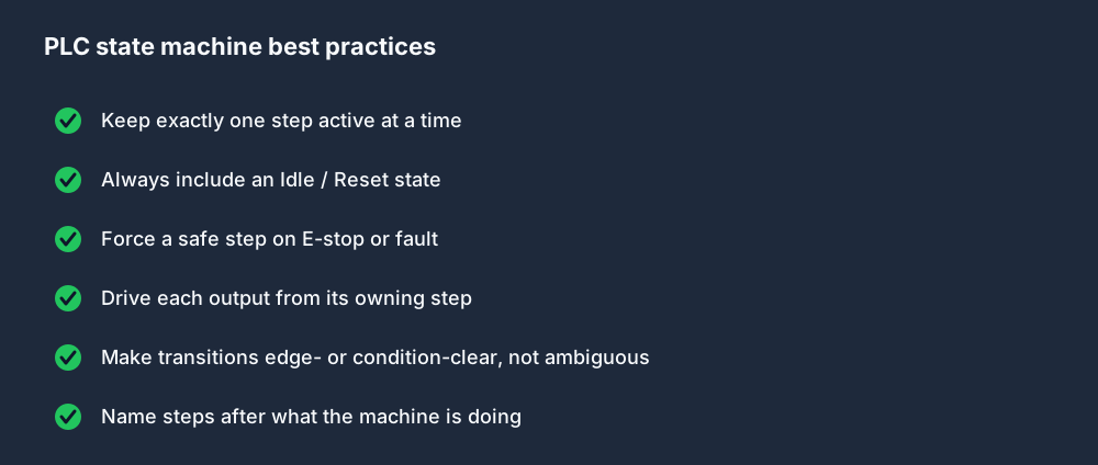
The two that save the most pain: always include an Idle/Reset state you can fall back to, and make sure an E-stop or fault forces the machine into a known safe step rather than freezing it mid-sequence.
Parallel and branching sequences
Real machines are not always one straight line. Grafcet and SFC let you branch — choose one of several paths based on a condition (an alternative branch) — or run parallel steps that all execute at once and rejoin later (a simultaneous branch).
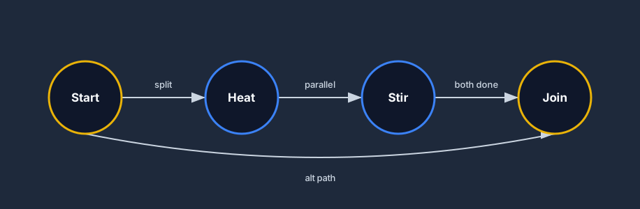
A divergence picks a path; a convergence waits for the active branches to finish before continuing. This is how you model "either fill from tank A or tank B" (alternative) or "heat and stir at the same time" (parallel) without abandoning the clean step-and-transition structure.
Design the state table before choosing ladder, SFC, or Structured Text
The diagram is the overview; the state table is the engineering contract. Write one row per state and include the outputs or actions owned by the state, the transition condition, timeout, abnormal exit, and restart rule. This exposes missing decisions before syntax makes the sequence look finished.
| State | Actions while active | Normal transition | Timeout / fault transition | Restart policy |
|---|---|---|---|---|
| Idle | Outputs off; clear cycle-complete indication | Start request and all start permissives | None; remain idle and report blocked reason | Always permitted after reset conditions are true |
| Fill | Open inlet valve; monitor level and flow | High-level condition or target quantity reached | No-flow timeout → Fault | Do not repeat a completed material addition |
| Mix | Run agitator; accumulate mix time only with feedback | Valid running feedback for the required duration | Motor trip or feedback loss → Hold/Fault | Resume timer only if product policy permits |
| Drain | Open outlet path; monitor low level | Low-level condition and confirmed transfer | No level change or route loss → Fault | Reconcile material and receiving-vessel state first |
| Complete | All process commands off; record cycle result | Reset or next-batch authorization | Record/report failure → review state | Create a new cycle identity before starting again |
The phrase “level high” is not yet a complete transition. Decide whether the signal needs quality, persistence, hysteresis, or agreement with a transferred quantity. State whether the transition is evaluated continuously, on an edge, or after an action is established. If two transitions can be true in the same scan, define their priority or make them mutually exclusive. Otherwise, implementation order silently chooses the path.
Output ownership belongs in the same table. If Fill owns the inlet valve and Drain owns the outlet valve, a reviewer can see that both should never be commanded by normal sequence states at once. Common interlocks still belong in the device module, but the sequence should not scatter competing writes across steps. The table is also the fastest way to review whether every active state has an exit and every fault has a recovery destination.
Structured Text CASE example with observable acceptance tests
A CASE implementation can make mutually exclusive state ownership explicit. Use a typed enumeration where the platform supports it, or named constants rather than unexplained integers. Separate state transition from device feedback: assigning ValveOpenCmd := TRUE is not proof that the valve opened.
CASE State OF
    Idle:
        InletCmd := FALSE;
        MixerCmd := FALSE;
        OutletCmd := FALSE;
        IF StartRequest AND StartPermissive THEN
            State := Fill;
            StateElapsed := T#0s;
        END_IF;

    Fill:
        InletCmd := TRUE;
        IF LevelHigh AND LevelQualityGood THEN
            InletCmd := FALSE;
            State := Mix;
            StateElapsed := T#0s;
        ELSIF StateElapsed >= FillTimeout THEN
            InletCmd := FALSE;
            FaultCode := FillNoProgress;
            State := Fault;
        END_IF;

    Mix:
        MixerCmd := TRUE;
        IF MixerRunning THEN
            MixElapsed := MixElapsed + CycleTime;
        END_IF;
        IF MixElapsed >= MixTarget THEN
            MixerCmd := FALSE;
            State := Drain;
            StateElapsed := T#0s;
        ELSIF MixerCmd AND NOT MixerRunning AND StateElapsed >= StartTimeout THEN
            FaultCode := MixerNoFeedback;
            State := Fault;
        END_IF;

    Drain:
        OutletCmd := TRUE;
        IF LevelLow AND LevelQualityGood THEN
            OutletCmd := FALSE;
            State := Complete;
        ELSIF StateElapsed >= DrainTimeout THEN
            OutletCmd := FALSE;
            FaultCode := DrainNoProgress;
            State := Fault;
        END_IF;

    Complete:
        CycleComplete := TRUE;
        IF ResetRequest THEN State := Idle; END_IF;

    Fault:
        InletCmd := FALSE;
        MixerCmd := FALSE;
        OutletCmd := FALSE;
END_CASE;
Expected normal input story: start from Idle with permissives true, pulse StartRequest, raise LevelHigh, prove MixerRunning, accumulate the required mix duration, then raise LevelLow. Expected outputs: inlet, mixer and outlet commands become active only in their owning states; the final state becomes Complete. The passing result is the observable sequence—not exact source formatting.
The fault case is equally important. Start Fill but leave level unchanged until FillTimeout. Expected outputs: the inlet command becomes false, the state becomes Fault, and FaultCode identifies no fill progress. A recovery test must define whether Reset returns to Idle immediately, requires the level and route to be reconciled, or routes to a dedicated recovery state. Without that requirement, “add a reset button” is not an engineered recovery policy.
Ladder implementation without duplicate step ownership
Step bits work well when the team diagnoses ladder quickly, but they need the same transition discipline as an enum. One transition routine should decide which step deactivates and which activates. Output routines should read the active step rather than set sequence state in response to outputs. Cross-reference every step bit: multiple Set/Reset writers make the active state dependent on scan order.
Choose an initialization rule. On first scan, verify that one valid initial step is active. If retained step bits can survive power loss, detect zero active steps and multiple active steps separately; do not silently choose Idle before recording the invalid state. A “one-hot” invariant—exactly one active bit for a mutually exclusive sequence—can be checked every scan and asserted in automated tests.
| Ladder risk | Evidence to review | Preferred control |
|---|---|---|
| Two steps active | One-hot count or explicit invalid-state diagnostic | Centralize transition writes and test simultaneous conditions |
| No step active | First-scan and retained-state trace | Defined initialization and recovery state |
| Output written by several steps | Output cross-reference | One output owner reading resolved sequence state |
| Transition repeats for several scans | Step and condition trace | Change state atomically or use a transition pulse where required |
| Reset jumps into motion | Command, permissive, state and feedback trace | Reset to a non-moving reconciliation state |
Timeouts, aborts, holds, and the fault state
Every state that waits for a physical change needs a time expectation. A timeout does not necessarily mean the timer should trip the whole machine; it means the expected transition did not occur. The response can be a controlled stop, hold, retry, alternate route, or fault depending on process consequence. Record the expected condition and actual evidence so the technician knows whether to inspect input, command, feedback, or process progress.
Distinguish hold, stop, and abort. A hold aims for a stable condition from which continuation may be possible. A stop ends the procedure in an orderly way. An abort may drive a more immediate response and require reconciliation before restart. These meanings are process-specific. Freezing all outputs and leaving the state number unchanged is rarely a complete strategy because the physical process may continue moving, heating, draining, or losing pressure.
Fault state design should preserve the initiating state, first fault, time, and relevant process values. If every later alarm overwrites the first cause, troubleshooting starts from a consequence. Decide whether the fault state owns ordinary commands, delegates to device modules, or requests a higher-level shutdown. Functional safety remains a separate validated design; a sequence state machine is not a safety controller merely because it has a state called Safe.
Restart and recovery policy after power loss or interruption
Restart begins with physical truth, not the saved state number. The PLC may remember “Mix,” while the vessel has cooled, an operator has drained it, or a shared transfer route now belongs to another batch. Reconcile sensors, feedback, material state, allocated resources, active commands, and the current recipe or work order before resuming.
Define one of three policies for each state: restart from the beginning, resume from a proven checkpoint, or require operator/engineering disposition. Idempotence matters. Closing a valve twice is usually harmless; adding the same ingredient twice is not. A recovery table should identify actions that may be repeated and actions that require evidence of completion.
For a controller warm restart, test retained and non-retained state separately. Verify timers, counters, one-shots, step bits, commands, and HMI requests. For a cold restart, test default values and first-scan initialization. The acceptance result must include prevention of unexpected motion: a maintained run request should not automatically energize equipment unless that restart behavior is explicitly designed and approved.
Worked batch and clean-in-place sequence
Consider a vessel that runs Product, Drain, Rinse, Caustic Wash, Final Rinse, and Complete. The product sequence and clean-in-place sequence share valves, pumps, level instruments, and transfer paths, but they have different material and completion requirements. Model shared equipment as capabilities, then let the active procedure request those capabilities rather than duplicating device logic in every step.
During Product, a Fill operation might use target quantity and ingredient identity. During CIP, a Rinse operation might use conductivity, return temperature, and minimum circulation time. Both can call a Transfer capability, but the parameter limits, route validation, and completion criteria differ. This is where state-machine design connects naturally to the ISA-88 batch-control model: procedural state requests reusable equipment behavior.
Test route conflict, loss of flow, high level, pump feedback failure, temperature not reached, and operator hold. Then test recovery from each state. A correct normal trace is only the first row of the matrix.
Tests that prevent illegal transitions
Build an executable transition matrix. Each test starts from a known state, applies one input story over scan time, and asserts the next state plus all affected commands and fault evidence.
- Normal path: every legal transition advances once and only once.
- Guard false: the transition does not advance when one permissive or quality condition is missing.
- Boundary time: completion just before timeout passes; completion at and after the specified boundary follows the written requirement.
- Contradictory sensors: high and low level together produce a diagnostic path rather than a believable transition.
- Unexpected feedback: a device running without command and a command without feedback are distinguished.
- Abort in every active state: outputs and next state match the state-specific policy.
- Restart: cold and warm restart cannot create illegal motion or repeat non-idempotent work.
- Invariant: mutually exclusive sequences never have zero or multiple active states outside explicitly permitted initialization.
Use fresh runtime state per independent test. Retained timers or step bits can otherwise allow one passing case to hide a failing next case. Keep the failed input sequence, actual state, expected state, program version, and trace so the result is reproducible. The PLC program-testing guide shows how to separate unit, integration, simulation, FAT, SAT, and commissioning evidence.
Primary references and implementation boundary
IEC 61131-3 defines SFC elements for structuring programs and function blocks; PLCopen provides a current public IEC 61131-3 overview and publishes SFC structuring guidance. Vendor runtimes define the exact action qualifiers, execution order, language support, retention, debugging, and online-change behavior. Validate those details in the official documentation for the target toolchain.
This browser product supports state-machine learning through ladder and Structured Text exercises, batch and sequence scenarios, and deterministic behavioral tests. It does not claim full SFC authoring, vendor runtime parity, safety validation, or ISA-88 conformance. Use it to prove the control idea; use the target controller, I/O, process, and approved commissioning plan to validate the industrial implementation.
Build a state machine in your browser
The fastest way to make sequencing click is to wire up a real step sequence and watch the active step move as conditions change. You can do exactly that in the free browser PLC simulator — build the step bits, set and reset them on transitions, and step through the scan to see exactly which state is active. Try it on one of the sequencing practice scenarios like a traffic light or a batch fill, where the whole point is getting the order right.
FAQ
What is a PLC state machine? A PLC state machine breaks a machine's behavior into a small set of named steps where only one step is active at a time, and you advance to the next step only when a defined transition condition becomes true. It makes sequential logic easy to read and debug.
What is the difference between Grafcet and SFC? Grafcet is the original graphical method (from French standard NF C 03-190) for describing a sequence as steps and transitions. Sequential Function Chart (SFC) is the IEC 61131-3 PLC programming language built on the same step-and-transition model.
Is SFC the same as ladder logic? No. SFC is a separate IEC 61131-3 language that shows the order of operations as a chart of steps and transitions, while ladder logic shows boolean rungs. You can implement the same state machine in either — SFC just makes the sequence visible.
How do you write a state machine in Structured Text?
Use a CASE Step OF block with one branch per step. Each branch drives that step's outputs and assigns the next value to Step when its transition condition becomes true, so exactly one step runs per scan.
Can you build a state machine in ladder logic? Yes. The portable pattern uses one step bit per state, driven by Set and Reset (latch/unlatch) coils: a transition rung sets the next step bit and resets the current one, so only one step is ever active.
What is the difference between a state machine and a PLC sequencer? A state machine makes named states, legal transitions, actions, and recovery explicit. A sequencer may use a step number, shift register, or table to advance through an ordered list. A sequencer can implement a state machine when it also defines guards, faults, and recovery clearly.
How do you test a PLC state machine? Start each case from a known state, apply an input sequence over scan time, and assert the next state, commands, feedback expectations, timeout, fault evidence, and recovery. Include illegal and contradictory transitions, not only the normal path.
What should happen to a PLC sequence after power loss? That is a process-specific requirement. Each state should restart from the beginning, resume from a proven checkpoint, or require disposition only after physical equipment, material, commands, feedback, and retained state are reconciled.
Can more than one SFC step be active? Yes. A simple sequential branch usually has one active step, while an intentional simultaneous or parallel divergence can activate one step in each branch until a defined convergence condition is satisfied.
Does a state machine make PLC logic safe? It can make modes, transitions, faults, and recovery easier to review, but it does not by itself provide a validated safety function. Safety requirements, architecture, diagnostics, hardware, verification, and lifecycle controls remain separate.