Motion and state
Its visible state changes with simulated I/O, making status and diagnosis readable in the scene.
sensors · indicator model
A PLC proximity sensor is a non-contact detector connected to a discrete input. An inductive model creates a high-frequency electromagnetic field at its active face; a nearby metal target absorbs energy from that field and makes the output transistor change state. The PLC does not see distance. It sees a clean ON or OFF input that the program can use for part presence, position proof, counting or an interlock.
Create a free account to run this scenario, or try a PLC lab now — no signup.
Explore Proximity sensor in 3D
Load the interactive model when you are ready to rotate, inspect and operate it. Deferring WebGL keeps the reference page fast.
Its visible state changes with simulated I/O, making status and diagnosis readable in the scene.
Commission it by proving detecting before accepting the next sequence state.
Inject stuck-on, stuck-off, misaligned states and require the PLC sequence to detect, stop and recover deliberately.
PLC integration guide
A three-wire DC sensor normally has brown for positive supply, blue for 0 V and black for the switched output, but the datasheet remains authoritative. A PNP sensor sources positive voltage into a sinking PLC input when active. An NPN sensor sinks current toward 0 V for a sourcing input. The sensor and input common must form a complete current path. Guessing from wire colour or changing only the PLC program cannot repair an incompatible electrical circuit.
Name the tag for what the sensor proves, such as CYLINDER_RETRACTED or PART_AT_STOP, rather than SENSOR_1. For a motion command, start a travel timer and require the expected position within a justified interval. Reject impossible combinations such as both mutually exclusive end sensors being true. For a counter, use a one-shot or edge detector so one stationary target contributes one count rather than one count per PLC scan.
Rated sensing distance is measured with a standard target under controlled conditions. Small targets, non-ferrous metals, a recessed mounting arrangement, temperature and nearby metal can reduce usable range. Leave margin instead of commissioning at the edge of detection. Secure the cable, protect the active face from impact and verify the target remains aligned across machine tolerance and vibration.
The reference above focuses on PLC integration. The interactive school lesson shows the device, signal or mechanism before you write the control sequence.
Open the inductive proximity sensor labSignal map
PLC input Detecting
| Signal | PLC direction | Type / range |
|---|---|---|
| Detecting detecting | input | bool |
Field checklist
Fault finding
| Symptom | Check |
|---|---|
| Sensor LED changes but PLC input stays off | Check PNP/NPN compatibility, input common, output conductor continuity and the correct input address. |
| Input chatters near the target | Increase sensing margin, correct alignment, inspect mounting vibration and apply only the minimum justified input filtering. |
| Input remains on with no target | Remove metal swarf, inspect a shorted output wire, check the configured polarity and substitute a known-good sensor. |
Fault and recovery exercise
Inject stuck-on, stuck-off, misaligned states and require the PLC sequence to detect, stop and recover deliberately.
The model teaches PLC sequence behaviour and diagnosis. Confirm ratings, wiring, guarding, process calculations and commissioning limits against the real manufacturer documentation and site design.
Plain-English answers
A standard inductive proximity switch is a discrete detector, not a distance transmitter. Some analog or IO-Link devices expose a process value, but the ordinary three-wire output provides only a switching state.
Filter only when the application and response-time requirement permit it. First correct vibration, marginal range or wiring noise; a long software delay can hide a real fast event.
A healthy-state signal can make some broken-wire conditions visible, but it does not automatically create a safety function. The complete circuit and diagnostic requirement determine the design.
Free first success
Open a related browser scenario, run the PLC logic and see the component state respond. Start without installing software or entering a card.
Keep building
sensors
Its visible state changes with simulated I/O, making status and diagnosis readable in the scene.
sensors
Its visible state changes with simulated I/O, making status and diagnosis readable in the scene.
sensors
Its visible state changes with simulated I/O, making status and diagnosis readable in the scene.
Technical reference and worked-example guide
Direct answer
The reader can define target and mounting conditions, choose a compatible output circuit and isolate target, device, wiring, input and program faults.
Written for pLC learners and maintenance technicians connecting inductive, capacitive or other proximity outputs to controller inputs and machine logic.
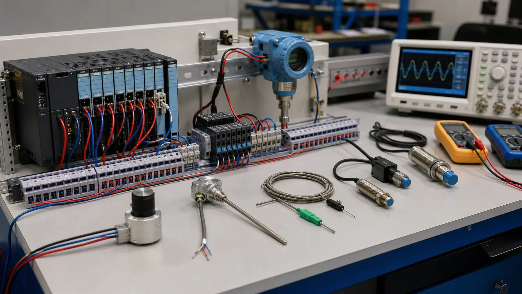
Target, material, size, distance, approach, speed, mounting, environment, supply, PNP or NPN output, normally open or closed state, PLC input and failure response.
Target presence through sensor field and output transistor, wiring and common, PLC input indication, tag, logic decision and independent machine evidence.
Representative target absent and present across the declared operating window with repeatable switching points.
Marginal distance, slow edge, contamination, nearby metal, moisture, wrong common, open cable, shorted output, restart and changed target.
A target, principle, mounting, adjustment, supply, output, wiring, input, polarity or logic mismatch.
The selected sensor proven on actual targets and input hardware across environmental and speed boundaries.
Match its supply and PNP, NPN or other output to a compatible input circuit and common, then verify both device indication and controller state.
Real targets may differ in size, material, approach, speed, distance, background or contamination; test representative motion and mounting.