A defensible PLC sequence normally starts the suction fan first, proves the required extraction condition, starts and proves the rotary valve, and only then permits upstream material feed. On a normal stop, it removes feed first, lets the rotary valve clear for an engineered delay, runs the required purge or filter-cleaning phase, and stops the fan last. Any trip must follow the approved process cause-and-effect design; the PLC must not invent the safe response.
That short answer describes the control order, not a production-ready program. A real extraction, dust-collection, pneumatic-conveying, fume-control, or process-purge system can contain combustible material, hidden moving vanes, stored pressure, hot particles, hazardous substances, explosion isolation, fire suppression, or environmental permit requirements. The machine designer and site risk assessment must define what “safe” means for each failure.
This guide builds a vendor-neutral sequence that you can adapt into ladder logic, Structured Text, a sequential function chart, or a state machine. It deliberately separates commands from proof, explains two different meanings of “purge,” gives a tag list and cause-and-effect matrix, and supplies normal, boundary, fault, and recovery tests. Use it as a design-review and training framework. Do not copy it into operating plant without equipment-specific engineering and validation.
First define what the three functions actually do
The same words describe several different systems. Before writing a rung, document the physical process.
Suction fan. The fan creates the required airflow or negative pressure at a pickup point, enclosure, duct, collector, vessel, or conveying line. A run command is only controller intent. Useful proof may include starter or VFD running status plus an independent airflow, differential-pressure, static-pressure, or process condition. The correct proof depends on what loss of extraction means in this system.
Rotary valve or rotary airlock. The valve meters bulk material while limiting air leakage between two pressure regions. In a dust collector it may discharge collected material from a hopper. Its motor-running auxiliary does not prove rotor motion, material flow, adequate isolation, or absence of a blockage. Where a rotary valve is part of explosion isolation, its construction, clearances, certification, installation, material level, maintenance and interlocks are specialized design matters—not ordinary PLC assumptions.
Purge system. “Purge” needs an explicit definition. It can mean a post-run air sweep that keeps the fan operating after material feed stops so residual dust leaves the duct. It can also mean compressed-air pulses that clean filter media, an inert-gas purge, a valve-manifold blowdown, or a process-specific cleaning sequence. Those functions do not share one safe start order. Name the purge medium, destination, required pressure or flow, permitted operating states, duration, feedback and failure response.
The OSHA dust-collection eTool describes rotary locks as motor-driven airlocks used to dump collected material while maintaining a pressure boundary. OSHA also publishes a separate rotary-valve amputation-hazard bulletin, which is a strong reminder that a stopped command bit is not energy isolation and that hidden vanes remain a serious maintenance hazard.
System architecture: command, proof, process result
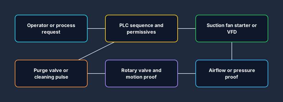
Build the control narrative as an evidence path:
- An operator or upstream process requests extraction.
- The PLC checks permissives that the process and safety design says belong in standard control.
- The PLC commands the fan starter or VFD.
- Electrical running status proves that the drive path accepted the command.
- Airflow or pressure proof establishes the required process condition.
- The PLC commands the rotary valve.
- Valve motion or another approved feedback confirms that the discharge path is available.
- Only then does the PLC issue an upstream feed permit.
- During a stop, feed is removed before the equipment that clears or contains the material.
- Trips remove permission and place each device in the state defined by the cause-and-effect matrix.
This model prevents a common error: using Fan_Run_Cmd as proof that extraction exists. The PLC can turn on the bit even when the disconnect is open, overload is tripped, VFD is faulted, belt is broken, damper is closed, duct is blocked, filter differential pressure is excessive, or the fan rotates incorrectly. Each layer answers a different question.
| Layer | Example signal | What it proves | What it does not prove |
|---|---|---|---|
| Operator/process | System_Run_Req | Someone or something requests operation | Equipment is available or safe to start |
| PLC output | Fan_Run_Cmd | Standard control is asking the drive to run | Starter, VFD, motor or airflow is healthy |
| Electrical feedback | Fan_Drive_Run | Starter/VFD reports running | Correct rotation, airflow or extraction at pickup |
| Process feedback | Airflow_OK | The selected switch/transmitter crossed its valid criterion | Every duct branch or collector function is healthy |
| Valve output | Rotary_Run_Cmd | Standard control requests the valve motor | Rotor motion, discharge, clearances or isolation performance |
| Valve feedback | Rotary_Motion_OK | Selected motion proof is present | No wear, blockage, material leakage or explosion-isolation defect |
| Feed permission | Upstream_Feed_Permit | Extraction sequence permits material entry | Upstream machine has started safely |
| Purge feedback | Purge_Ready / Purge_OK | Defined purge resources or response are available | Purge is suitable for every process or trip condition |
For more on this distinction, use the PLC troubleshooting signal-path guide and PLC data-logging guide. They show how to preserve the first disagreement instead of resetting the final alarm.
Example PLC I/O and internal tags
The following list is intentionally generic. Add the exact electrical, process, environmental, fire, explosion-protection, guarding and maintenance interfaces defined by the project.
| Tag | Type | Direction | Purpose |
|---|---|---|---|
System_Run_Req | BOOL | Input/internal | Maintained production or operator request |
System_Stop_Req | BOOL | Input/internal | Normal controlled-stop request |
Reset_Req | BOOL | Input/internal | Deliberate reset request after causes are clear |
Process_Permissives_OK | BOOL | Internal | Standard-control permissives combined for display and sequence use |
Safety_Healthy | BOOL | Input/status | Read-only status from the engineered safety system; not the safety function itself |
Fan_Available | BOOL | Input | Starter/VFD ready and no standard-control fault |
Fan_Run_Cmd | BOOL | Output | Fan run request |
Fan_Drive_Run | BOOL | Input | Starter/VFD running status |
Airflow_OK | BOOL | Input | Valid airflow or pressure criterion |
Filter_DP_High | BOOL | Input/internal | High differential-pressure condition, if applicable |
Rotary_Available | BOOL | Input | Valve starter ready and no standard-control fault |
Rotary_Run_Cmd | BOOL | Output | Rotary valve run request |
Rotary_Motion_OK | BOOL | Input | Approved rotation, zero-speed, current, or motion proof |
Hopper_High | BOOL | Input | High material level, where provided |
Purge_Available | BOOL | Input | Purge pressure, valve bank, or system-ready status |
Purge_Cmd | BOOL | Output | Defined purge or cleaning command |
Purge_OK | BOOL | Input | Optional proof appropriate to the purge design |
Upstream_Feed_Permit | BOOL | Output/internal | Permission for upstream process to introduce material |
First_Trip_Code | integer/enum | Internal | First initiating trip captured until deliberate reset |
Sequence_State | enum | Internal | Current operating state |
Fan_Proof_Timer | timer | Internal | Maximum allowed time for running and airflow proof |
Rotary_Proof_Timer | timer | Internal | Maximum allowed time for valve motion proof |
Clearout_Timer | timer | Internal | Engineered run-on time after feed stops |
Purge_Timer | timer | Internal | Engineered purge duration or cycle boundary |
Avoid one large All_OK bit as the only diagnostic. A combined permissive can drive a rung, but the HMI, alarm history and test record should retain the individual reasons. If the bit drops, capture which condition changed first.
Recommended startup sequence
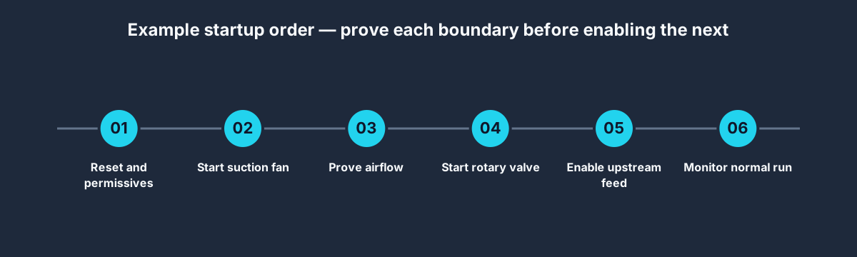
1. Establish the stopped state
Define what must be true before reset: no active initiating trip, commands off, feedback coherent, required guards or protection healthy, process equipment in an acceptable state, and no temporary force or maintenance bypass active. A reset should clear a latched diagnostic only after its cause has cleared. It should not create an automatic restart unless the approved process design explicitly requires and safeguards that behavior.
2. Check start permissives
Typical standard-control permissives might include fan and rotary starter availability, purge-resource availability when needed, acceptable hopper or filter status, selected dampers in the required position, downstream collection capacity and upstream/downstream handshake readiness. Do not place a safety function in ordinary application logic merely by calling the input Safety_Healthy; the safety system architecture and validation remain separate.
3. Start and prove the suction fan
Set Fan_Run_Cmd, start the proof timer and wait for the defined combination of electrical and process feedback. A robust sequence can distinguish “drive did not run” from “drive runs but airflow did not establish.” That distinction sends maintenance to different boundaries.
Do not hide a slow or failing system by increasing the timer until it stops alarming. Establish a normal baseline across expected operating conditions, then choose the limit from process and equipment evidence. If airflow falls later during production, the response may be different from a failed startup; document both.
4. Start and prove the rotary valve
Only after the extraction condition is valid should the sequence command the rotary valve in this example. Start its proof timer and wait for the selected feedback. A motor auxiliary is useful, but an application with blockage or motion risk may require zero-speed, shaft rotation, current signature, material level, downstream capacity or other evidence.
The exact order can differ. Some engineered systems require the discharge device to run before the fan, or require several components to operate continuously. The project process narrative decides. The important rule is that every transition has an explicit reason and proof.
5. Permit upstream material feed
Set Upstream_Feed_Permit only when the fan, airflow, rotary valve and other required states are valid. Prefer a permission handshake to directly commanding someone else’s machine. The upstream controller should still apply its own permissives and sequence logic.
Remove this permit immediately when a condition that invalidates material entry occurs. Whether running equipment stops immediately, remains on to clear material, or follows a fire/explosion trip is a separate cause-and-effect decision.
6. Monitor the running state
During normal running, compare every command with proof and watch process conditions: airflow, differential pressure, hopper level, valve motion, purge readiness, motor/VFD status, upstream handshake and any engineered detection. Use time-qualified alarms where appropriate, but do not delay a response that the hazard analysis requires immediately.
Use a state model instead of scattered latches
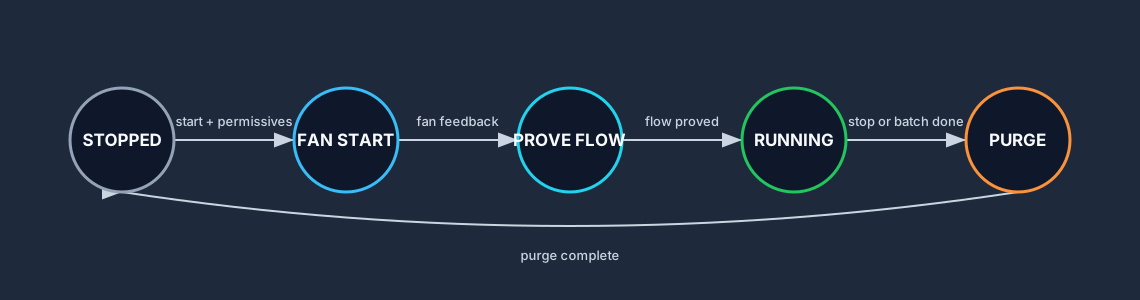
A state machine makes the operating contract visible. One example is:
| State | Outputs normally requested | Transition out | Timeout or invalid condition |
|---|---|---|---|
STOPPED | All process commands off | Start request and permissives → FAN_START | Stay stopped and show blocking reason |
FAN_START | Fan on | Drive run accepted → AIRFLOW_PROVE | Fan-start trip |
AIRFLOW_PROVE | Fan on | Airflow valid → ROTARY_START | Airflow-proof trip |
ROTARY_START | Fan and rotary valve on | Valve motion valid → RUNNING | Rotary-proof trip |
RUNNING | Fan, valve and feed permit on; purge as designed | Normal stop → CLEAROUT | Trip response selected by cause |
CLEAROUT | Feed off; fan and valve as designed | Clearout complete → PURGE | Timeout or process abnormality |
PURGE | Defined purge outputs; fan/valve states per design | Purge complete → STOPPING | Purge fault response |
STOPPING | Commands removed in approved order | Proofs return to stopped → STOPPED | Stop-timeout alarm |
TRIPPED | Cause-specific output pattern | Cause clear + deliberate reset → STOPPED | Stay latched and preserve first trip |
Keep TRIPPED as a result, not the only explanation. Record the first trip code and timestamp before other states cascade. For example, loss of airflow may soon produce a filter or feed alarm; the first loss is usually more diagnostic.
Illustrative Structured Text skeleton
This fragment shows organization, not production code. The timing constants, state transitions and trip actions are placeholders that the approved design must replace. Safety functions must not be implemented by copying this standard PLC example.
(* Illustrative vendor-neutral sequence skeleton. *)
CASE Sequence_State OF

    STOPPED:
        Fan_Run_Cmd := FALSE;
        Rotary_Run_Cmd := FALSE;
        Upstream_Feed_Permit := FALSE;
        Purge_Cmd := FALSE;

        IF Start_Edge AND Process_Permissives_OK THEN
            Sequence_State := FAN_START;
        END_IF;

    FAN_START:
        Fan_Run_Cmd := TRUE;

        IF NOT Fan_Available THEN
            First_Trip_Code := TRIP_FAN_NOT_AVAILABLE;
            Sequence_State := TRIPPED;
        ELSIF Fan_Drive_Run THEN
            Sequence_State := AIRFLOW_PROVE;
        ELSIF Fan_Proof_Timer.Q THEN
            First_Trip_Code := TRIP_FAN_START_TIMEOUT;
            Sequence_State := TRIPPED;
        END_IF;

    AIRFLOW_PROVE:
        Fan_Run_Cmd := TRUE;

        IF Airflow_OK THEN
            Sequence_State := ROTARY_START;
        ELSIF Airflow_Proof_Timer.Q THEN
            First_Trip_Code := TRIP_NO_AIRFLOW;
            Sequence_State := TRIPPED;
        END_IF;

    ROTARY_START:
        Fan_Run_Cmd := TRUE;
        Rotary_Run_Cmd := TRUE;

        IF Rotary_Motion_OK THEN
            Sequence_State := RUNNING;
        ELSIF Rotary_Proof_Timer.Q THEN
            First_Trip_Code := TRIP_ROTARY_NO_MOTION;
            Sequence_State := TRIPPED;
        END_IF;

    RUNNING:
        Fan_Run_Cmd := TRUE;
        Rotary_Run_Cmd := TRUE;
        Upstream_Feed_Permit := Run_Conditions_OK;

        IF NOT Run_Conditions_OK THEN
            First_Trip_Code := First_Invalid_Run_Condition;
            Sequence_State := TRIPPED;
        ELSIF Stop_Edge THEN
            Sequence_State := CLEAROUT;
        END_IF;

    CLEAROUT:
        Upstream_Feed_Permit := FALSE;
        Fan_Run_Cmd := TRUE;
        Rotary_Run_Cmd := Clearout_Rotary_Required;

        IF Clearout_Timer.Q THEN
            Sequence_State := PURGE;
        END_IF;

    PURGE:
        Upstream_Feed_Permit := FALSE;
        Fan_Run_Cmd := Purge_Fan_Required;
        Rotary_Run_Cmd := Purge_Rotary_Required;
        Purge_Cmd := Purge_Allowed AND Purge_Available;

        IF Purge_Timer.Q THEN
            Sequence_State := STOPPING;
        END_IF;

    STOPPING:
        Upstream_Feed_Permit := FALSE;
        Purge_Cmd := FALSE;
        Rotary_Run_Cmd := FALSE;
        Fan_Run_Cmd := FALSE;

        IF All_Stopped_Feedback_Coherent THEN
            Sequence_State := STOPPED;
        END_IF;

    TRIPPED:
        Upstream_Feed_Permit := FALSE;
        Apply_Approved_Trip_Response();

        IF Reset_Edge AND Trip_Causes_Clear AND All_Stopped_Feedback_Coherent THEN
            Sequence_State := STOPPED;
        END_IF;

END_CASE;
Three details matter more than the syntax:
Upstream_Feed_Permitdefaults false outside the proven running state.First_Trip_Codeis captured before cascading alarms overwrite the initiating cause.Apply_Approved_Trip_Response()is not generic logic. It represents a reviewed cause-and-effect matrix that defines each device state for each trip.
Use the PLC Structured Text guide for language mechanics and the PLC program-testing guide for acceptance cases.
Illustrative timing for normal start and stop
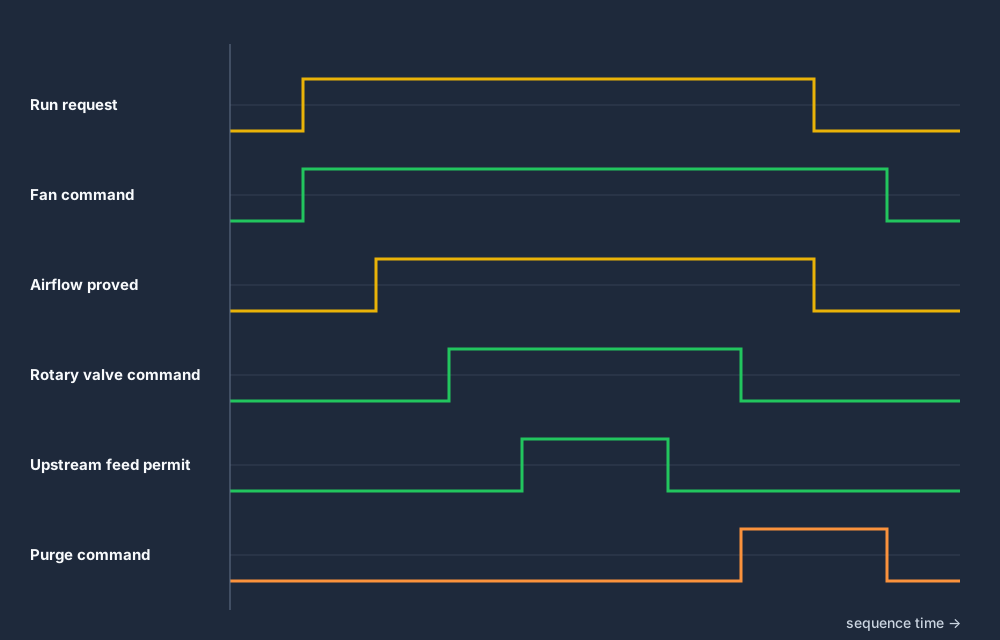
The diagram is qualitative; it does not prescribe seconds. It illustrates six principles:
- The fan command precedes the airflow proof.
- The rotary valve command waits for the required extraction condition in this example.
- The upstream feed permit waits for fan, airflow and valve proof.
- A normal stop removes material feed first.
- The clearing and purge phases occur while the equipment states required by the process remain available.
- The fan stops only after the approved clearing or purge boundary is complete.
Do not use a single off-delay timer as the entire sequence. A timer measures elapsed controller time; it does not prove that a duct cleared, a hopper discharged, a filter pulse occurred or a valve moved. Where the process needs proof, use the appropriate sensor or diagnostic and alarm on failure.
Command, proof, and trip matrix
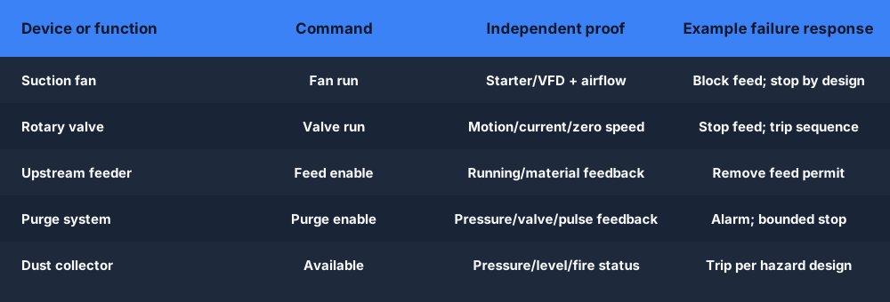
A cause-and-effect matrix is clearer than prose once several trips exist. The table below is an example review format, not a recommended universal response.
| Initiating condition | Remove feed permit | Fan response | Rotary valve response | Purge response | Reset expectation |
|---|---|---|---|---|---|
| Fan fails to start | Yes | Stop/failed | Do not start | Off unless specifically required | Cause clear + deliberate reset |
| Airflow not proved at startup | Yes | Stop or remain on for diagnosis per design | Do not start | Off unless approved | Cause clear + reset |
| Airflow lost while running | Yes | Cause-specific | Cause-specific | Cause-specific | Preserve first loss and inspect process |
| Rotary valve fails to move | Yes | Run-on or stop per hazard/process design | Stop/failed | Defined by process | Remove blockage/fault under isolation |
| Hopper high/high-high | Yes at selected threshold | Cause-specific | May continue discharge if safe | Cause-specific | Level and cause return to valid state |
| Filter differential pressure high | Often block or stop feed | Process-specific | Process-specific | Cleaning may be requested if allowed | Verify filter and extraction condition |
| Purge pressure unavailable | Usually block purge-dependent phase | Process-specific | Process-specific | Alarm or abort purge | Restore resource and retest |
| Fire/explosion protection trip | Yes | Defined by engineered protection system | Defined by engineered protection system | Do not assume ordinary purge is allowed | Specialist inspection and formal reset |
| Emergency stop or safety-system demand | Yes | Safety design | Safety design | Safety design | Validated safety reset and restart policy |
The “cause-specific” entries are deliberate. Stopping a fan can remove extraction, while continuing a fan can move burning material or affect protection performance. Stopping a rotary valve can remove discharge, while continuing it can spread material or conflict with an isolation function. There is no responsible universal answer outside the equipment hazard and protection design.
The UK Health and Safety Executive notes that rotary valves used as explosion chokes need appropriate design and certification, and its combustible-dust guidance distinguishes ordinary powder-flow equipment from tested explosion-isolation devices. OSHA’s combustible-dust technical manual similarly treats specialized rotary valves as protection devices with design, installation, maintenance and interlock requirements. Standard PLC logic cannot manufacture those physical properties.
Normal stop and purge sequence
Remove the source first
Clear Upstream_Feed_Permit and wait for the upstream handshake to confirm that new material entry has stopped where the process requires proof. Keep the extraction and discharge equipment in the states needed to handle material already in the system.
Run the engineered clearout phase
The fan may need to run on so residual suspended material reaches the collector. The rotary valve may need to continue so collected material leaves the hopper. The correct duration can come from process testing, transport velocity, duct volume, measured conditions or equipment guidance. A generic five- or ten-second delay has no authority merely because it is common in example code.
Execute the correct purge function
For a duct air sweep, the fan may remain on and the material feed remains off. For a filter pulse-cleaning cycle, fan state, damper state, compressed-air pressure, pulse order and differential-pressure logic may be different. For inerting or process gas, the sequence may require gas analysis and specialist controls. Give each function a distinct name such as Duct_Clearout, Filter_Pulse_Clean, or Inert_Gas_Purge rather than one ambiguous Purge bit.
Stop in the approved order
Remove the purge command, stop the rotary valve and fan in the order defined by the process, and verify that running feedback returns to the expected state. An unexpected running feedback after the command is removed should produce a diagnostic; it must not be silently accepted as “stopped.”
Reset without surprise motion
On the next start, compare stored sequence state with real equipment and process feedback. After a PLC restart, do not resume a mid-sequence value simply because it was retentive. Reconcile the physical state, clear temporary commands, require coherent feedback and apply the approved restart policy.
Trip-response workflow
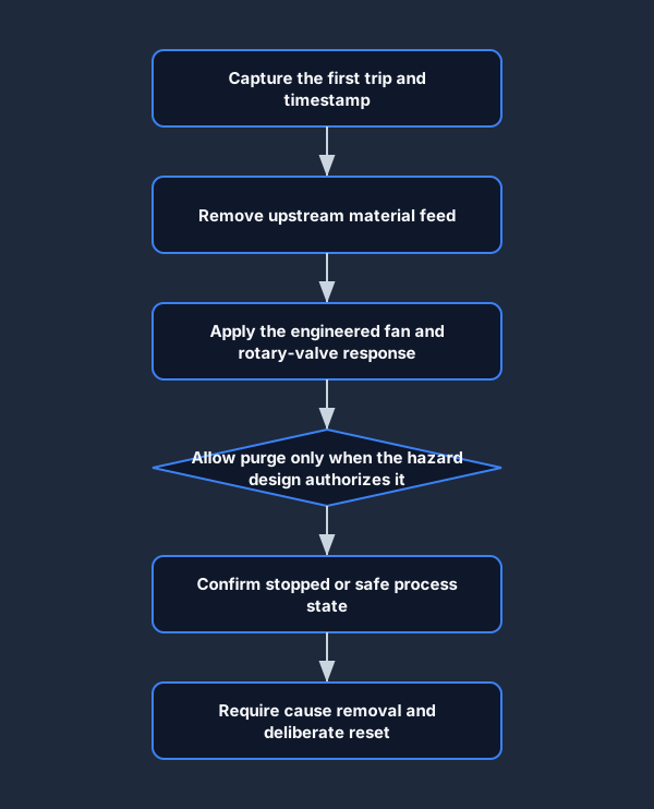
When a trip occurs:
- Capture the first invalid condition, state and timestamp.
- Remove permission for additional material feed unless the approved design specifies a different action.
- Apply the cause-specific fan and rotary-valve states.
- Allow a purge only if that purge is authorized for that trip. A cleaning pulse, air sweep or inerting action can be inappropriate during some fire, explosion, pressure or equipment conditions.
- Confirm the process reaches its defined stopped, isolated or otherwise controlled state.
- Latch the initiating trip until the cause is removed and a deliberate reset is accepted.
- Repeat the affected start, run, stop and trip tests after repair.
Alarm acknowledgement and trip reset should be separate concepts. Acknowledgement records that an operator saw an alarm. Reset requests that the control sequence leave a latched fault state after conditions are valid. Neither action proves that a blocked duct, worn valve, lost airflow, fire hazard or maintenance exposure has been corrected.
Ladder-logic organization
If you implement this in ladder logic, divide the program by responsibility rather than placing the complete sequence in one rung:
- Input conditioning: raw inputs, validation, debounce and quality.
- Permissive summary: each named reason plus the combined start permission.
- Device modules: fan command/feedback/timeout and rotary command/feedback/timeout.
- Sequence state: mutually exclusive steps or explicit integer/enum state.
- Feed handshake: permission, request, accepted state and lost-handshake diagnostic.
- Purge module: named purge type, resource proof, phase and result.
- Trip capture: first-out code, time and sequence state.
- Alarm mapping: actionable message, consequence, operator response and reset boundary.
- HMI tags: commands, status, feedback, blocking reasons and maintenance diagnostics kept distinct.
Avoid scattered seal-in coils that can hold contradictory states. A start latch, fan latch, rotary latch, purge latch and fault latch distributed across routines can make restart behavior difficult to prove. An explicit state owner reduces duplicate writes and gives every transition a visible reason.
Commissioning and regression test matrix
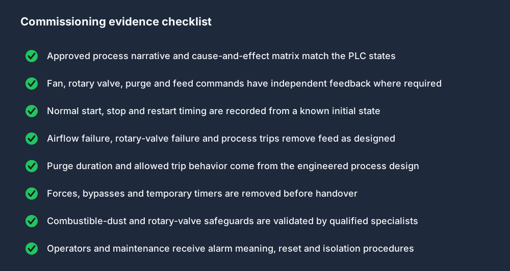
Run tests from documented initial conditions. Record input values, state, commands, proof, timer results, first trip, operator message and recovery. Do not perform live fault injection on production equipment unless the approved commissioning method, risk controls and responsible specialists authorize it.
| Test | Initial condition | Stimulus | Expected evidence |
|---|---|---|---|
| Normal startup | System stopped; all start permissives valid | Apply run request | Fan command, run feedback and airflow proof occur before valve and feed permit |
| Fan unavailable | Fan not ready | Apply run request | Start remains blocked; exact blocking reason visible; no valve/feed command |
| Fan start timeout | Fan ready; feedback withheld in approved simulation/test | Apply run request | Feed remains blocked; first trip identifies fan start timeout |
| Airflow failure | Fan feedback present; airflow invalid | Start or remove airflow during test | No feed permit at startup; running response follows matrix |
| Rotary unavailable | Fan/airflow valid; valve not ready | Apply run request | Valve start is blocked; feed remains off; reason visible |
| Rotary motion timeout | Valve commanded; motion proof absent | Continue approved test | Feed remains off; first trip identifies valve motion failure |
| Normal stop | Stable running condition | Apply stop request | Feed is removed first; clearout/purge occur; equipment stops in approved order |
| Stop during startup | Fan-start or proof state | Apply stop request | Sequence reaches defined stopped state without feed permission |
| Purge unavailable | Stable run; purge resource not ready | Apply stop request | Response matches whether purge is required, optional or prohibited |
| Feedback disagreement | Command off but running feedback remains | Stop device in approved test | Diagnostic identifies unexpected running feedback; no false stopped state |
| Power or PLC restart | Equipment states physically simulated and recorded | Restart controller/model | Sequence reconciles feedback and requires the defined restart action |
| Repeated cycle | Restored known state | Run multiple complete cycles | Timing and transitions remain deterministic with no retained hidden command |
| First-out preservation | Inject one initiating fault followed by cascaded statuses | Observe alarm history | First trip remains the initiating condition until deliberate reset |
| Maintenance return | All work complete and isolated tests released | Restore system | Bypasses/forces cleared; normal and affected fault cases pass |
The PLC watchdog guide helps test bounded execution, while the motor-control circuit simulator helps distinguish a PLC command from contactor and motor evidence.
Troubleshooting by symptom
| Symptom | Inspect first | Likely boundary | Proving action |
|---|---|---|---|
| Fan command on, no run feedback | Starter/VFD ready, fault, control path and command reception | PLC-to-drive or drive-to-motor | Read exact drive/starter status before reset |
| Fan running, no airflow proof | Rotation, damper, duct, filter, switch/transmitter and proof threshold | Mechanical/process measurement | Compare pressure or airflow at approved points |
| Rotary command on, no motion proof | Starter, overload, shaft sensor, blockage and feedback mapping | Drive/mechanical/feedback | Isolate energy before any physical blockage inspection |
| Feed starts too early | State transitions and feed-permit equation | Sequence ownership | Trend fan, airflow, valve proof and feed permit together |
| Purge runs during a trip | Purge allow matrix and trip priority | Cause-and-effect logic | Prove which condition owns purge permission |
| System will not reset | Active cause, incoherent feedback, stopped state and reset edge | Recovery contract | Show every blocking reason; do not bypass the first one |
| Intermittent airflow trip | Timestamped pressure, fan speed, damper, filter DP and process demand | Process margin or sensor quality | Capture a triggered pre/post-event window |
| Hopper level rises | Rotary motion, discharge path, downstream capacity and level device | Material handling | Verify motion and downstream availability without reaching into equipment |
Rotary valves create a specific maintenance boundary. Never treat a PLC stop, HMI stop, VFD stop or zero-speed indication as lockout. The OSHA rotary-valve bulletin documents severe injuries when people reached into equipment whose vanes were not effectively isolated. Use the employer energy-control procedure, equipment-specific isolation points and verification before access.
Questions people ask about this PLC sequence
What is the correct start sequence for a suction fan and rotary valve?
A common sequence is to check permissives, start the fan, prove the required airflow or pressure, start and prove the rotary valve, and only then permit material feed. The real process narrative can require a different order, so every transition must be justified by equipment and hazard design.
Should the fan or rotary valve start first?
It depends on the system. Starting the fan first is common when extraction must exist before material moves. Some systems require the discharge device first or continuous operation. Use the approved process narrative rather than copying a universal timer sequence.
How do I prove that a suction fan is running in PLC logic?
Separate electrical running feedback from process proof. A starter auxiliary or VFD status can show that the drive accepted the command; an airflow or pressure device can show whether the required extraction condition exists.
What interlocks should a rotary valve have?
Possible interfaces include motor/starter availability, overload or VFD fault, shaft or zero-speed proof, hopper level, downstream capacity and process protection status. The exact set and response come from the mechanical, process and hazard design.
Can a motor auxiliary contact prove rotary-valve motion?
It proves the starter or drive state, not necessarily rotor movement. A broken coupling, jam or other mechanical failure can leave the motor circuit running without useful valve motion. Use the evidence appropriate to the consequence.
What is a purge timer in PLC logic?
It measures the allowed duration of a specifically defined purge phase. It does not prove that a duct is clear, compressed air flowed, filter media cleaned or inert-gas concentration reached its target. Add the required feedback and failure response.
Should the fan stop immediately on an airflow or dust-collector trip?
There is no universal answer. Removing extraction can worsen some conditions, while continuing airflow can worsen others. The fire, explosion, process and equipment cause-and-effect design must define the response for each initiating condition.
How should the system stop normally?
Remove upstream material feed first, keep the equipment needed to clear or contain existing material running for the engineered boundary, execute the defined purge or cleaning phase, then stop the rotary valve and fan in the approved order.
What should happen after a PLC restart?
Reconcile the stored state with physical feedback, keep feed permission off until the complete sequence is proven, clear temporary outputs and follow the approved deliberate-restart policy. Do not blindly resume a retained mid-cycle state.
Is a rotary valve automatically an explosion-isolation device?
No. Ordinary material-handling use does not establish explosion-isolation performance. Specialized design, certification, installation, clearances, material conditions, maintenance and interlocks may be required under the applicable protection design.
Can this sequence be implemented in ladder logic?
Yes. Use explicit steps or state bits, separate device command and proof, prioritize trips, capture the first initiating condition and test every transition. Structured Text or SFC can express the same operating contract.
Can I simulate this sequence online?
You can model the state sequence, timers, fan and valve commands, proof signals, feed permission, purge phase and fault cases in a PLC simulator. Simulation does not validate the real extraction, dust, explosion, pressure, electrical or mechanical system.
Final design checklist
Before the control review is complete, confirm that the project has:
- one approved process narrative that defines start, normal run, stop, purge, trip and restart;
- one signal list that separates command, electrical feedback, process proof and safety/protection status;
- one state owner with visible transition reasons;
- one cause-and-effect row for every initiating trip;
- first-out trip capture and useful timestamps;
- device-specific proof timers based on evidence rather than copied values;
- an explicit definition of each purge function and when it is allowed;
- tested loss-of-proof, stop-during-start, trip-during-run and restart cases;
- documented physical safety, combustible-dust, explosion-protection and isolation ownership;
- a handover record showing that forces, bypasses and temporary test changes are removed.
The transferable programming principle is simple: start from the physical contract, enable material only after extraction and discharge are proven, remove the source before clearing the system, and never let a command bit masquerade as process proof. The hard part—and the part that must remain equipment-specific—is the safe state for each failure.
Continue with PLC sequence and state-machine design, build the acceptance cases in PLC program testing, inspect motor evidence in the motor-control simulator, and retain first-out evidence with the PLC data-logging guide.