Direct answer: A variable frequency drive converts fixed-frequency AC to DC in a rectifier, smooths and stores that energy in a DC bus, then uses high-speed power transistors in an inverter to create variable-frequency, variable-voltage output for the motor. Changing output frequency changes the motor's rotating-field speed; the drive regulates voltage/current to produce the required flux and torque.
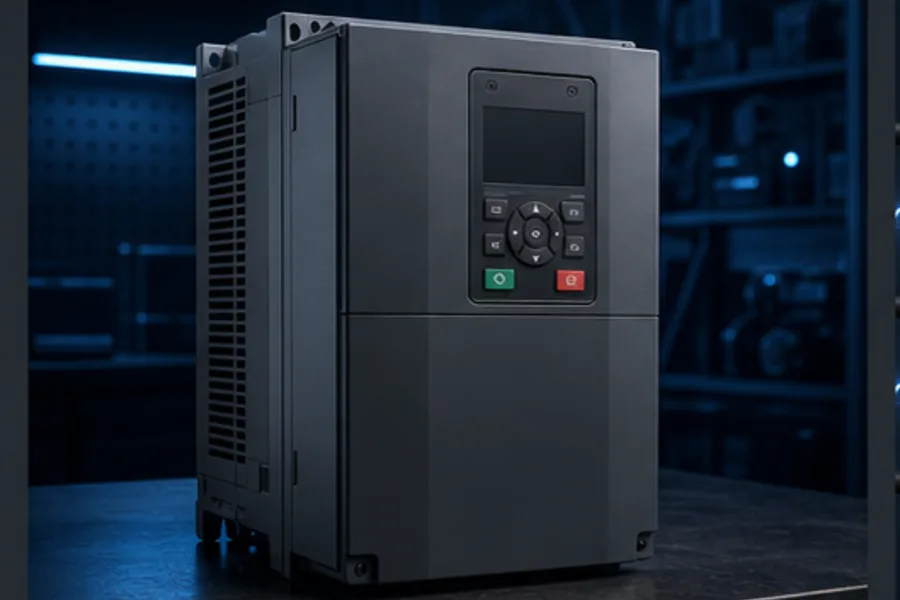
“A VFD reduces voltage” is not a sufficient explanation. The drive rebuilds the output waveform electronically. Understanding its three power stages makes commissioning, PLC control and fault diagnosis much clearer.
Stage 1: rectifier—AC becomes DC
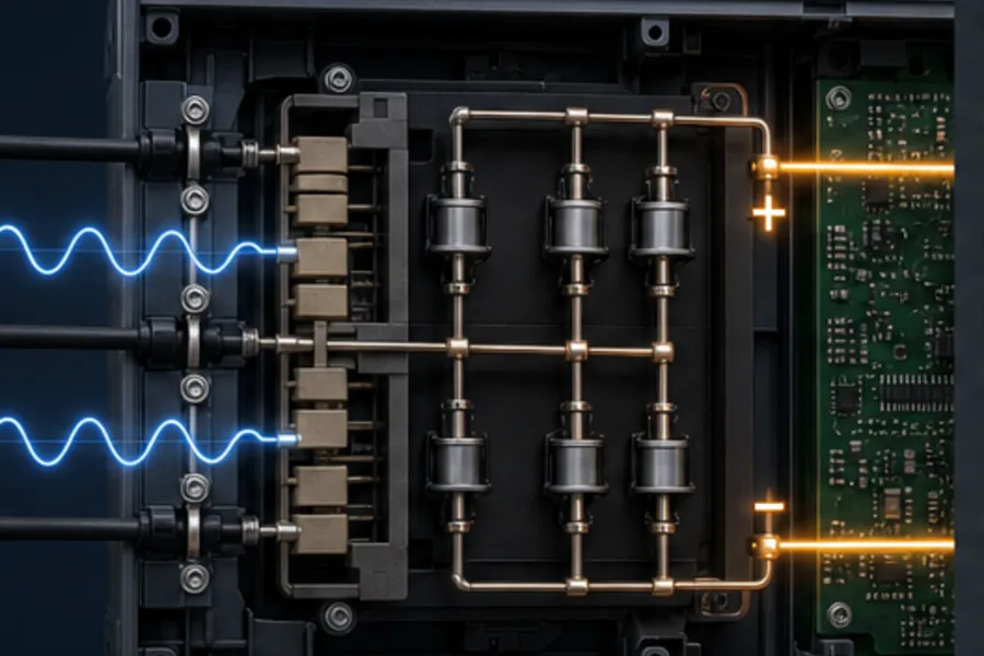
The incoming supply reaches a diode bridge or another converter topology. In a typical six-pulse low-voltage drive, the diodes conduct in pairs and rectify the three-phase AC into a pulsating DC voltage.
The rectifier draws current in pulses rather than as a perfect sine wave, which contributes harmonics. Larger or demanding installations may use line reactors, DC chokes, harmonic filters or active-front-end drives. The correct mitigation depends on the installation study—not a universal accessory list.
The DC bus remains hazardous after supply isolation because its capacitors store energy. Observe the manufacturer's discharge time and verify with the approved procedure.
Stage 2: DC bus—store and smooth energy
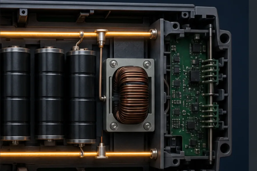
Capacitors reduce the ripple in the rectified voltage and provide a relatively stiff energy reservoir for the inverter. A choke may reduce ripple current and harmonics. Pre-charge components limit the initial charging current when power is first applied.
This middle stage is why a VFD is not simply a variable transformer. It decouples the fixed-frequency input from the synthesized output.
Common DC-bus related states include:
- undervoltage: input supply is low/lost or bus cannot stay charged;
- overvoltage: regenerated mechanical energy charges the bus faster than the drive can dissipate/return it;
- pre-charge fault: the bus did not charge along the expected path; and
- capacitor ageing: increased ripple or reduced energy storage.
Stage 3: inverter—DC becomes variable AC
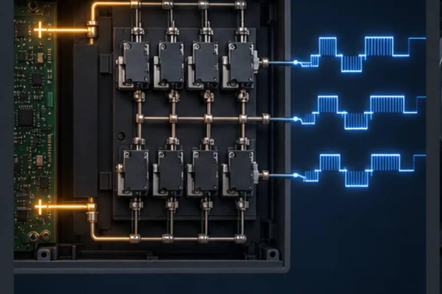
Six power switches—commonly IGBTs in many low-voltage drives—connect the motor phases to the positive and negative DC rails in a controlled sequence. Pulse-width modulation changes the width/timing of the voltage pulses so the motor current and magnetic field behave like a variable-frequency AC supply.
ABB's drive guidance describes the same chain: rectifier, DC link and inverter. Its technical guide notes that PWM varies pulse width so the average phase-to-phase voltages follow the required sinusoidal pattern.
The motor does not need a visibly smooth sine voltage at its terminals. Motor inductance filters much of the high-frequency current ripple, while insulation, cable length, switching frequency and reflected-wave effects must still be considered in the application design.
Why frequency changes speed
The synchronous speed of an AC motor's rotating field is:
Ns = 120 × f / P
where Ns is synchronous speed in revolutions per minute, f is electrical frequency in hertz, and P is the number of motor poles.
A four-pole motor has a 1,500 rpm synchronous speed at 50 Hz and 1,800 rpm at 60 Hz. An induction motor runs slightly below synchronous speed because it needs slip to produce torque.
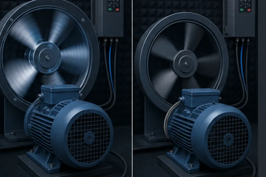
Below base speed, simple scalar control commonly maintains an appropriate volts-per-hertz relationship to preserve motor flux. Vector-control methods estimate or measure motor state to control flux and torque more independently. The exact parameters—motor nameplate data, autotune, current limits, acceleration and deceleration—matter as much as the speed command.
How a PLC commands the drive
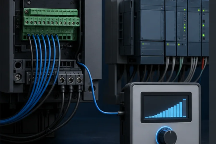
A PLC does not normally synthesize the motor waveform. It tells the VFD what to do. Common interfaces are:
| Signal | Typical implementation | Purpose |
|---|---|---|
| Run enable | digital output or network bit | allow/start motion |
| Direction | digital output or command word | select forward/reverse when permitted |
| Speed reference | 0–10 V, 4–20 mA or network value | requested frequency/speed |
| Ready/running | digital inputs or status word | drive state feedback |
| Fault | relay output or status word | diagnostic state |
| Actual speed/current | analog/network feedback | proof and process information |
Network control can carry commands, references, status and diagnostics in one cyclic data connection. Hardwired enable and safety functions may remain separate depending on the design.
Start/stop methods matter
VFD parameters often support two-wire maintained run, three-wire momentary start/stop, keypad control and network control. A machine can fail to start simply because its command-source or reference-source parameter points to the wrong interface.
Record the selected control mode and parameter set. “The drive is healthy” does not mean it is listening to the terminal the PLC is driving.
VFD safety is more than a normal Stop bit
A normal PLC command can request controlled deceleration. An emergency stop may require Safe Torque Off (STO), a safety-rated drive function, upstream isolation or another architecture selected by risk assessment.
STO prevents the drive from producing motor torque but normally does not isolate hazardous voltage. It also does not guarantee a moving load stops instantly. Mechanical brakes, stop category and vertical/gravitational loads need engineered consideration.
Do not repeatedly open a contactor between a running VFD and motor unless the drive/system is specifically designed and sequenced for that action. Switching the output under load can cause drive faults or damage.
Acceleration, deceleration and overvoltage
An aggressive acceleration time demands high torque/current. An aggressive deceleration time can make the motor regenerate energy into the DC bus. If that energy has nowhere to go, the drive trips on DC-bus overvoltage.
Options include a longer deceleration time, braking resistor/chopper, regenerative drive, or mechanical/process changes. Selecting one requires load inertia and duty analysis.
For fans and centrifugal pumps, reducing speed can save substantial energy because the required power changes strongly with speed. For constant-torque conveyors, the relationship differs. Do not apply fan affinity-law savings to every load.
Common VFD faults as a causal chain
| Fault | What it usually means | First investigation |
|---|---|---|
| Overcurrent | demanded torque/current exceeded limit | jam, short accel, motor/cable, tune |
| DC overvoltage | bus is being charged too strongly | decel time, regenerative load, supply |
| Undervoltage | bus cannot maintain voltage | supply, fuses, phase loss, pre-charge |
| Overtemperature | cooling cannot remove losses | fan, filter, cabinet temperature, load |
| Ground/earth fault | leakage or insulation problem | motor cable, motor insulation, moisture |
| Communication loss | command/status network failed | topology, timeout, addressing, PLC state |
The fault history, current at trip, DC-bus state and operating mode are more useful than clearing the alarm immediately.
Use the interactive power path
The Variable Frequency Drive lesson lets you step through rectification, bus charging and inverter switching, then vary speed and see the motor response. Recognition content is public; the interactive mechanism and contextual AI tutor are Pro.
Then compare the architecture with a direct-on-line starter in Motor Starter vs VFD.
Frequently asked questions
Does a VFD change voltage or frequency?
It controls both as part of producing the required motor flux and torque. The headline speed effect comes from frequency, but the drive also regulates voltage/current according to its control method and motor parameters.
Can a VFD convert single-phase input to three-phase output?
Some drives are specifically rated for single-phase input and three-phase motor output, often with derating or limited power range. Never assume a three-phase-input drive can be used that way without manufacturer approval.
Is the VFD output a sine wave?
The inverter produces high-frequency PWM voltage pulses. Motor inductance makes the current more sinusoidal, but cable/motor insulation still experiences switching effects that the application design must address.
Why does a VFD trip when stopping?
Rapid deceleration can make the motor regenerate energy into the DC bus, raising bus voltage. Increase deceleration time or use an engineered braking/regeneration solution appropriate to the load.
Can a PLC control VFD speed?
Yes. It can send a 0–10 V or 4–20 mA reference, write a network command/reference, or select preset speeds with digital outputs. The drive must be parameterized to use that source.
