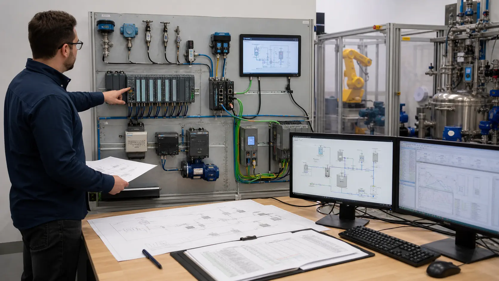
Direct answer: Industrial automation is a closed loop. Sensors measure the process, I/O translates field signals, the PLC evaluates logic, actuators change the physical process, and the HMI lets an operator observe and request actions. Power, networks and safety make that loop reliable and safe.
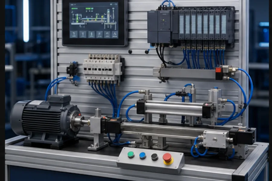
Memorising a list of component names is less useful than understanding the causal path between them. A box reaches a photoeye; the input module changes; the PLC runs a rung; an output energises a solenoid; a cylinder diverts the box; a limit sensor proves the move; the HMI reports the state.
The complete signal-and-energy loop
Physical process
   ↓ measured by
Sensors/transmitters → input modules → PLC logic → output modules
   ↑ feedback                                   ↓ commands
HMI / historian / diagnostics ← network ← drives, relays, valves, actuators
Electrical power and compressed air supply the energy. Safety controls limit dangerous behavior. Documentation connects the drawing, terminal, PLC tag and physical device.
1. Sensors: turn physical conditions into signals
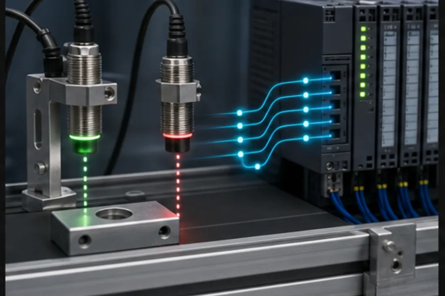
Sensors answer questions about the real machine:
| Physical question | Common component | Typical PLC signal |
|---|---|---|
| Is the part present? | inductive/photoelectric sensor | 24 V digital input |
| Where is the cylinder? | reed/limit sensor | 24 V digital input |
| How full is the tank? | level switch/transmitter | digital or 4–20 mA |
| What is the pressure? | pressure switch/transmitter | digital or 4–20 mA |
| How fast is the shaft? | encoder | pulses/high-speed input/network |
| What is the temperature? | RTD/thermocouple/transmitter | resistance/mV/4–20 mA |
A sensor is not just an input tag. It has a sensing principle, range, response time, target/material constraint, electrical output type and failure mode. Learn those mechanisms in Sensor School.
2. I/O modules: translate field electricity
Digital input modules interpret ON/OFF voltages. Digital outputs source or sink current to coils, lamps and interface relays. Analog inputs measure voltage/current/resistance. Analog outputs command proportional devices.
Important distinctions include:
- sourcing versus sinking and PNP versus NPN;
- isolated versus shared commons;
- relay versus transistor/triac outputs;
- raw counts versus engineering units;
- standard versus high-speed inputs; and
- ordinary versus safety-rated I/O.
A green input LED is useful, but the tag, terminal voltage, field state and wiring drawing must agree.
3. PLC: deterministic decision making
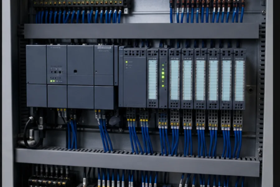
The PLC repeatedly reads inputs, executes logic and updates outputs. Its program contains:
- permissives and interlocks;
- sequences/state machines;
- timers and counters;
- analog scaling and PID control;
- alarm latches and diagnostics;
- communication handling; and
- controlled startup/recovery behavior.
The PLC must not merely make the machine run. It should explain why it cannot run, detect command/feedback disagreement and recover predictably after stop, fault and power transitions.
4. Actuators: create physical change
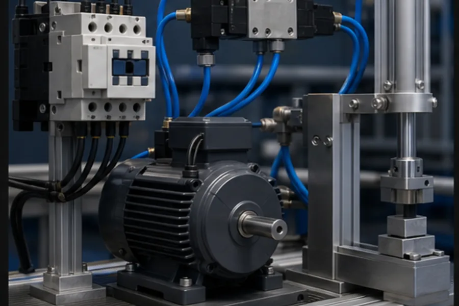
Actuators convert electrical, pneumatic or hydraulic energy into motion/flow:
- Contactor + motor starter: on/off motor control and protection.
- VFD + motor: variable speed/torque.
- Solenoid valve + cylinder: fast linear movement using compressed air.
- Control valve: modulates process flow/pressure/temperature.
- Heater/SSR/contactor: changes process temperature.
- Servo drive + motor: precise closed-loop position and motion.
The output bit commands an interface. Feedback proves the physical result.
5. HMI: operator intent and explanation
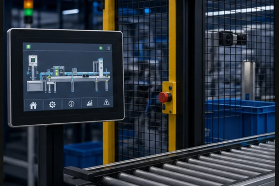
An HMI reads/writes PLC tags. It should:
- show current state and next blocked condition;
- send commands to PLC logic, not bypass interlocks;
- prioritize abnormal conditions with restrained colour;
- provide actionable alarm cause and recovery steps;
- respect roles/security; and
- preserve a usable state when communication fails.
The PLC remains in control if the HMI restarts. A screen button should set START_REQUEST; ladder logic decides whether MOTOR_RUN is safe.
6. Industrial networks: move state with timing guarantees
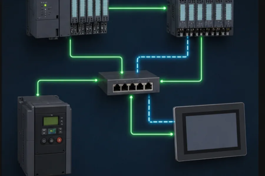
Networks connect remote I/O, drives, HMIs and supervisory systems. Common technologies include EtherNet/IP, PROFINET, EtherCAT, Modbus TCP/RTU, IO-Link and OPC UA.
Choose based on topology, update time, determinism, diagnostics, installed ecosystem and lifecycle support—not popularity alone. Define what the machine does on stale/missing data. A communication timeout is a control state that needs an engineered response.
7. Control-panel power and switching
A typical panel also contains:
- main disconnect and protective devices;
- 24 VDC power supply;
- terminal blocks and earth terminals;
- control relays/interposing relays;
- contactors and overload relays;
- safety relay or safety PLC;
- network switch;
- surge/suppression devices;
- cooling and environmental controls; and
- wire markers, drawing references and spare terminals.
Component choice is inseparable from short-circuit rating, selectivity/coordination, heat, enclosure, EMC and maintenance access.
8. Safety components
Safety functions may use guard switches, light curtains, E-stops, safety relays/PLCs, safety contactors, STO and monitored feedback. “Safety” is a validated system behavior, not a red button connected to a normal input.
The risk assessment defines required performance. The safety design must consider detection, logic, output devices, diagnostic coverage, reset, stopping time and stored energy.
Follow one real sequence
For a pneumatic pick-and-place:
- Photoeye detects a part.
- Input module presents
PART_PRESENTto the PLC. - PLC confirms guard, air pressure, home sensor and no fault.
- Output module energises a 5/2 solenoid valve.
- Valve routes air to extend a cylinder.
- Extended sensor proves the motion before timeout.
- PLC advances the state and updates the HMI.
- If proof does not arrive, the PLC de-energises safely and reports the exact missing feedback.
Every component school lesson should ultimately reconnect to a sequence like this.
Selection questions that prevent category errors
Before selecting hardware, ask:
- What physical variable or action is required?
- Is the signal discrete, analog, pulse or networked?
- What voltage/current/pressure/force/speed is involved?
- What failure state is safest?
- What environment—temperature, washdown, dust, vibration, hazardous area?
- What response time and repeatability matter?
- How will the PLC prove the command occurred?
- How will a technician diagnose it from drawing to terminal to tag?
- What safety integrity is required?
- How will it be replaced and supported over the machine lifecycle?
Start with recognition, then mechanism, then application
Industrial Components School teaches the physical components beginners encounter in motor, pneumatic and safety circuits. Each lesson starts with recognition and plain-English purpose, then shows the internal mechanism and connects it to a scenario. Interactive cutaways and the contextual AI tutor are Pro features.
Use Sensor School for detection principles, then start the free simulator to see the input→logic→output loop run.
Frequently asked questions
What are the four main parts of industrial automation?
Sensors, controller, actuators and operator interface form the simplest useful model. Real systems also need I/O, power, networks, safety and documentation.
Is a PLC an industrial automation component or the whole system?
It is one component—the deterministic controller. Without sensors, outputs, actuators and power, the PLC has nothing to observe or control.
What is the difference between a sensor and an actuator?
A sensor converts a physical condition into information for the controller. An actuator converts a controller command and energy source into physical action.
Where do relays and contactors fit?
They are switching/interface components on the output side. Relays commonly switch control-level loads or isolate PLC outputs; contactors switch higher-power loads such as motors.
What should a beginner learn first?
Learn the closed loop first: input sensor, PLC rung, output device and physical feedback. Then learn each component's mechanism and wiring in the context of a complete machine sequence.