Direct answer: A three-pole contactor has two separate circuits. The power circuit enters at L1/L2/L3 and leaves for the load at T1/T2/T3. The control circuit energises the electromagnetic coil at A1/A2. A normally-open auxiliary contact such as 13–14 can provide seal-in or PLC feedback. The coil voltage and main-contact voltage are separate ratings.
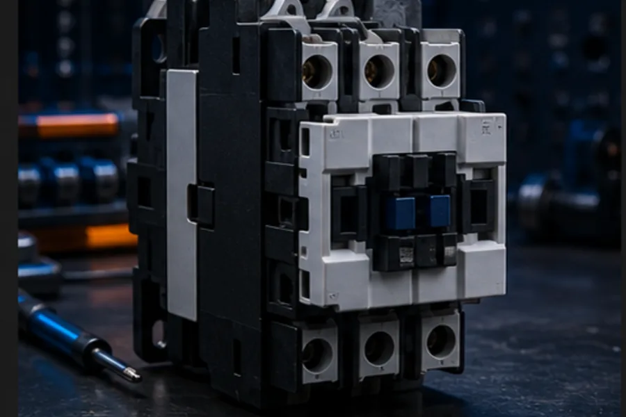
The most common beginner mistake is treating every terminal as part of one circuit. A contactor is useful precisely because a low-power control circuit can command a separate, higher-power load circuit.
How a contactor works internally
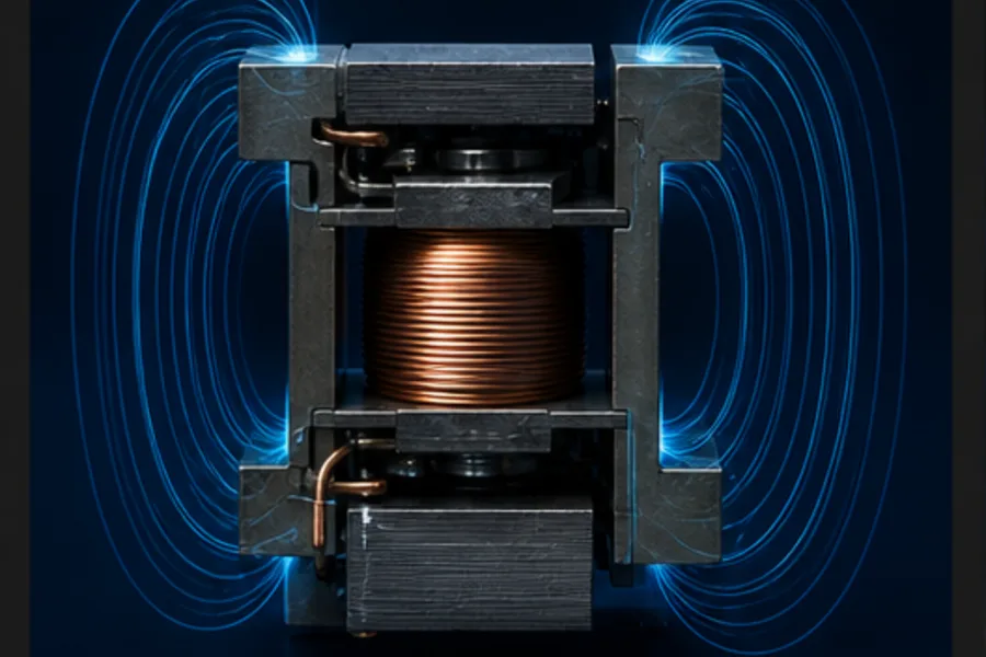
Applying the rated voltage across A1 and A2 drives current through a coil. The coil creates a magnetic field in an iron core, pulling a moving armature across an air gap. The armature is mechanically linked to the main and auxiliary contacts.
When the coil is de-energised, return springs push the armature back. Normally-open contacts open; normally-closed contacts close. This is why the words normally open and normally closed describe the de-energised, mechanically normal state—not what the machine usually does.
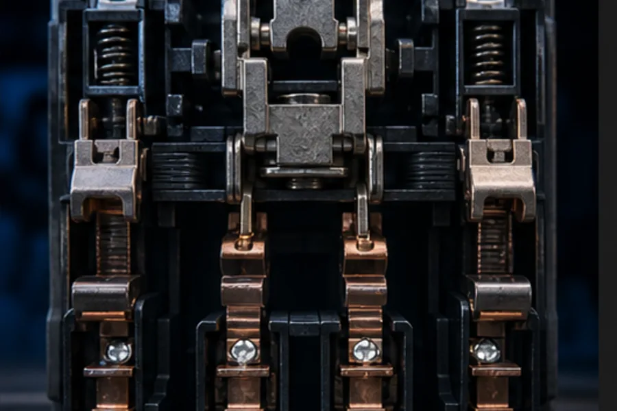
The contactor is not a motor-protection device by itself. It switches. A coordinated fuse/breaker handles short circuits, and an overload relay handles sustained motor overcurrent.
Main terminal map
IEC markings commonly follow this pattern:
| Function | Incoming side | Outgoing side |
|---|---|---|
| Phase 1 | 1/L1 | 2/T1 |
| Phase 2 | 3/L2 | 4/T2 |
| Phase 3 | 5/L3 | 6/T3 |
| Coil | A1 | A2 |
| NO auxiliary | 13 | 14 |
| NC auxiliary | 21 | 22 |
Always confirm the diagram printed on the actual device. Pole count, auxiliary blocks, AC/DC coil suppression and vendor numbering can differ.
Three-phase power wiring
The power path for a direct-on-line starter is:
Supply L1 ─ protection ─ contactor 1/L1 → 2/T1 ─ overload ─ motor U
Supply L2 ─ protection ─ contactor 3/L2 → 4/T2 ─ overload ─ motor V
Supply L3 ─ protection ─ contactor 5/L3 → 6/T3 ─ overload ─ motor W
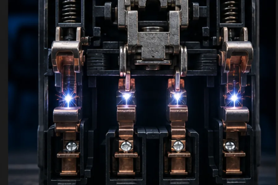
When the armature pulls in, all three main poles close together. When the coil drops out, all three open together.
Motor rotation is established by phase sequence. Changing it requires an approved reversing arrangement with two mechanically/electrically interlocked contactors—not swapping conductors while energised.
Classic three-wire control circuit
A hardwired start/stop circuit uses a momentary NO Start button, a momentary NC Stop button and a NO auxiliary seal-in contact:
+24 V ─ STOP NC ─ overload 95–96 NC ─┬─ START NO ─────┬─ A1
                                     └─ AUX 13–14 NO ┘
0 V  ───────────────────────────────────────────────── A2
Pressing Start energises the coil. The armature closes the main poles and auxiliary 13–14. That auxiliary bypasses the released Start button, so the contactor remains energised. Pressing Stop or tripping the overload opens the series path and drops the coil.
This is called a three-wire circuit because the control station traditionally needs a control feed, a stopped/start return path and a holding path. It is also called seal-in, holding or latching control.
Wiring a contactor from a PLC output
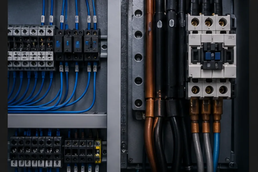
With PLC control, ladder logic usually performs the seal-in. The output drives the contactor coil directly only when the output rating, coil inrush/holding current, voltage, suppression and safety design permit it. An interposing relay is often used.
Example 24 VDC sourcing-output concept:
+24 V supply → PLC output-group common
PLC output Q0.0 → overload 95–96 → contactor A1
contactor A2 → 0 V
For a sinking output the current path is different. Do not copy the sourcing example without checking the PLC module wiring diagram.
For a DC coil, provide the suppression specified by the contactor/output manufacturer. A plain flyback diode clamps slowly and can delay contactor release; a diode-plus-zener/TVS or purpose-built suppressor may be required where fast dropout matters. AC coils use different suppressors.
PLC feedback: command is not proof

A true output tag proves only that software requested the contactor. It does not prove the armature moved or the power poles closed. Wire an auxiliary contact to a PLC input such as K1_AUX and compare command with feedback:
| Command | Feedback | Interpretation |
|---|---|---|
| 0 | 0 | stopped normally |
| 1 | 1 | contactor followed the command |
| 1 | 0 | failed to pull in, open coil path or mechanical fault |
| 0 | 1 | welded/stuck contactor or feedback wiring fault |
Use a short, engineered proof timer to avoid faulting during normal mechanical pull-in/dropout time.
Choosing the right coil
The main-contact rating does not tell you the coil voltage. The same contactor frame may be sold with a 24 VDC, 24 VAC, 110/120 VAC or 220/230 VAC coil. Check:
- nominal coil voltage and AC/DC type;
- permitted pickup/dropout range;
- inrush and sealed power;
- built-in suppression or polarity requirement; and
- control source/output rating.
Applying 230 V to a 24 V coil destroys it. Applying 24 V to a 230 V coil may produce no movement or contact chatter.
What contact arcing means
Opening a current-carrying inductive load creates an arc. Contactor main contacts use suitable spacing, materials and arc-control geometry for their utilization category. That is why a small control relay is not an acceptable substitute for a motor contactor even if its headline current number appears close.
The correct contactor selection depends on load category, current, voltage, switching frequency, ambient temperature and coordination with protective devices—not current alone.
Safe commissioning checks
Safety: isolate, lock out, test for absence of voltage and follow the site's electrical procedure. Never use a browser article as authorization to work live.
Before energising:
- Verify device and coil ratings against the drawing.
- Tug-test terminated conductors and confirm torque requirements.
- Check L/T direction and that all phases pass through the overload as designed.
- Confirm 95–96 is in the coil path and fault feedback reaches the correct input.
- Test Stop, overload and safety removal before relying on Start.
- Compare PLC command to auxiliary feedback.
- Check all phases and motor current under controlled commissioning conditions.
Learn it by moving the armature
Open the public Contactor lesson to identify the coil, iron core, armature, main poles and auxiliary contact. The Pro cutaway lets you energise the coil and trace the physical state into the PLC feedback signal. Then build the control rung in the Motor Start/Stop scenario.
For the selection difference, see relay vs contactor. For fault diagnosis after a starter fails, use the motor starter troubleshooting guide.
Frequently asked questions
What are A1 and A2 on a contactor?
They are the two coil terminals. Apply the coil's rated control voltage across A1/A2 and the electromagnetic armature pulls in. They do not carry the motor's main power.
What are L1, L2, L3 and T1, T2, T3?
L terminals are the incoming line side of the three main poles. T terminals are the outgoing load side. IEC devices may print 1/L1, 3/L2, 5/L3 and 2/T1, 4/T2, 6/T3.
What does auxiliary contact 13–14 do?
It is commonly a normally-open contact that closes when the contactor pulls in. It can provide a hardwired seal-in path or return physical contactor status to a PLC input.
Can a PLC output drive a contactor directly?
Sometimes, but only when output type/rating, coil current, voltage, suppression and safety design all match. Many systems use an interposing relay to protect the PLC output and provide isolation.
Why does a contactor chatter?
Common causes include low or unstable coil voltage, the wrong coil type, a contaminated/damaged magnetic face, loose control wiring or an AC shading-ring problem. Chatter rapidly damages contacts and should be corrected rather than ignored.
