What you'll learn
Build the front end of a real control panel: incoming three-phase supply, door interlocked main isolator, branch circuit breaker, 24 VDC power supply, fused positive distribution and bonded protective earth. The lockable disconnect provides the point of isolation; the branch breaker protects the power-supply feeder; the downstream fuse localises a DC control fault.
Lab time: ~15 minutes.
Lesson briefing
Protected Control Power Distribution
Build the front end of a real control panel: incoming three-phase supply, door interlocked main isolator, branch circuit breaker, 24 VDC power supply, fused positive distribution and bonded protective earth. The lockable disconnect provides the point of isolation; the branch breaker protects the power-supply feeder; the downstream fuse localises a DC control fault.
The device in the real world
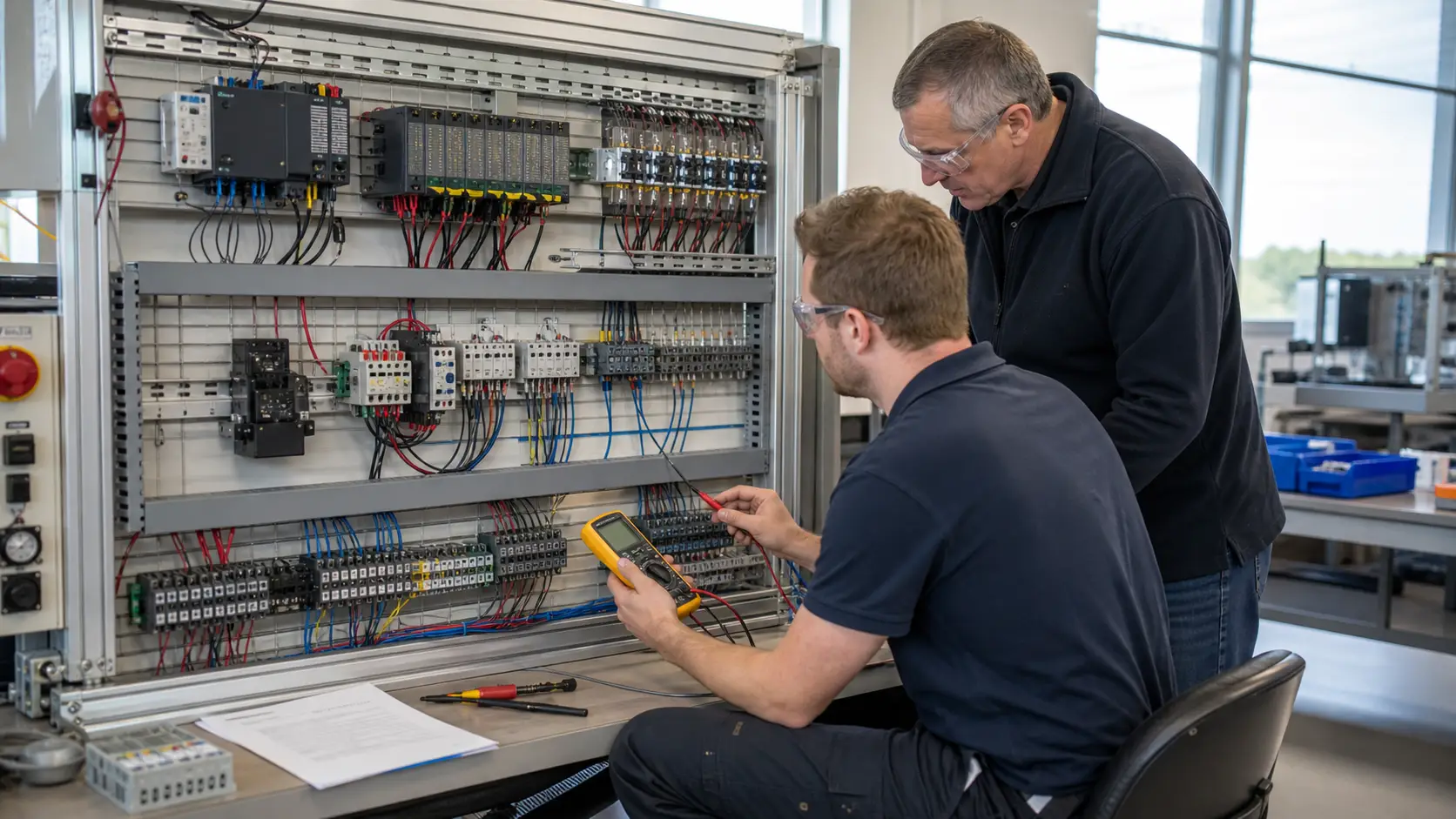
Open any machine control cabinet and the first things inside the door are a door-interlocked isolator, a small three-pole breaker and a DIN-rail 24 V power supply with a fuse holder next to it. The isolator is the padlockable point that lets a technician make the cabinet safe. The breaker is sized to protect the thin cable feeding the supply, not the machine. The supply turns the incoming alternating current into the steady 24 V direct current that every sensor, relay and PLC input in the cabinet uses. Panel builders repeat this front end on almost every machine, so being able to read it quickly is worth a lot.
Why it is wired this way
Protection is coordinated from source to load. PE is never switched or fused. Here the DC fuse sits in the positive (ungrounded) conductor, which is the usual practice when 0 V is the bonded reference: a downstream short clears the fuse while the grounded 0 V stays intact. Always follow the panel standard and drawing for your site.
Worked example
Picture a small packaging machine fed from a three-phase supply. Two of the phases go through the isolator and the breaker to the L and N terminals of a power supply rated for 230 V in, 24 V out. Suppose a sensor cable gets crushed on a hinge and shorts +24 V to 0 V. Because the fuse sits in the positive output, the fuse opens and the 24 V distribution rail goes dead, but the supply, the breaker and the isolator all stay on. The technician then measures 24 V at the supply output and 0 V on the far side of the fuse, and knows within a minute that the fault is downstream of F1. Wire the lab in the same order the energy flows: earth first, then the three phases, then the supply, then the fused 24 V rail and the 0 V rail.
Common mistakes
- Putting the DC fuse in the 0 V conductor. A short can then still feed current through the positive side, and the fuse protects nothing useful.
- Routing protective earth through the isolator or breaker. Earth is never switched, so it goes straight from the incoming terminal to the ground bar.
- Bonding 0 V to earth in more than one place, which creates a loop that carries noise current.
- Landing the supply on the wrong phase pair terminals and assuming the supply is faulty when the cause is a swapped L or N.
What you can now do
You can trace power from the incoming supply to a protected 24 V rail, explain what each protective device is for, and say where a fault will remove power if a branch cable is shorted.
Commissioning standard
With the isolator off and locked, check continuity of every earth conductor to the ground bar, then confirm that the DC fuse is in the positive conductor before anyone switches the panel on.
Training material. Follow your site procedures, local electrical code and the manufacturer's instructions. Lockout/tagout and a qualified person are required for real equipment.
Hints
Wire PE first and take it directly to the ground bar; it must bypass every switching device.
Sign up to unlock the full hint sequence.
Sign up to unlock the full hint sequence.
This lesson uses 9 placed components on the lab canvas. Components are vendor-neutral (no proprietary trademarks); the wiring rules apply to any equivalent industrial part.
Sign up free to start
This foundation lab is included on Free — sign up takes a minute.
Sign up free to start →