Motion and state
Its travel is animated along the validated local axis and can expose command and end-state feedback.
motion · linear model
A pneumatic cylinder in a PLC sequence is an actuator with a command path and a separate proof path. The PLC energises one or two solenoid-valve outputs to route compressed air, then waits for retracted or extended limit feedback. Reliable logic never assumes that an energised output means the rod moved: pressure can be absent, the valve can stick, the load can jam or the position sensor can fail.
Create a free account to run this scenario, or try a PLC lab now — no signup.
Explore Pneumatic cylinder in 3D
Load the interactive model when you are ready to rotate, inspect and operate it. Deferring WebGL keeps the reference page fast.
Its travel is animated along the validated local axis and can expose command and end-state feedback.
Commission it by proving extended limit, retracted limit before accepting extend.
Inject jammed, slow states and require the PLC sequence to detect, stop and recover deliberately.
PLC integration guide
Model the cylinder with explicit states such as RETRACTED, EXTENDING, EXTENDED, RETRACTING and FAULT. Before extending, confirm the retract command is off and every process permissive is healthy. Issue the extend command once, start a travel timer and advance only when EXTENDED_LS arrives. On timeout, stop dependent motion and report which command lacked which proof. This state-based pattern is easier to diagnose than scattered set/reset coils.
A single-solenoid spring-return valve moves to its normal state when its coil loses power. A double-solenoid valve may retain its last spool position, so turning both PLC outputs off does not necessarily return the actuator. Interlock opposing coils in logic and, where the hardware requires it, electrically. Define the intended state after controller restart, loss of air and emergency stop instead of relying on the last command bit.
Cylinder force depends on pressure and effective piston area, while speed depends on airflow, restrictions and load. PLC timing can detect abnormal travel but cannot compensate safely for poor sizing or an unstable pneumatic circuit. Meter-out flow control often produces steadier movement. Vertical loads and stored air can continue moving after electrical power is removed, so risk controls must address the pneumatic energy itself.
The reference above focuses on PLC integration. The interactive school lesson shows the device, signal or mechanism before you write the control sequence.
See the cylinder cutaway and airflow labSignal map
PLC output Extend; PLC input Extended limit; PLC input Retracted limit
| Signal | PLC direction | Type / range |
|---|---|---|
| Extend extend | output | bool |
| Extended limit extended | input | bool |
| Retracted limit retracted | input | bool |
Field checklist
Fault finding
| Symptom | Check |
|---|---|
| Output is on but cylinder does not move | Check supply pressure, isolation valve, coil voltage, manual override, spool movement, exhaust restriction and mechanical binding. |
| Cylinder moves but never completes the PLC step | Check end-sensor position, wiring, input address and whether the sequence expects the opposite limit. |
| Motion is jerky or too fast | Inspect flow-control direction, cushioning, side load, pressure stability and cylinder sizing before changing PLC timers. |
Fault and recovery exercise
Inject jammed, slow states and require the PLC sequence to detect, stop and recover deliberately.
The model teaches PLC sequence behaviour and diagnosis. Confirm ratings, wiring, guarding, process calculations and commissioning limits against the real manufacturer documentation and site design.
Plain-English answers
No. Use end-position feedback for normal completion and a timer as a fault limit. A timer-only sequence cannot distinguish completed travel from a stalled actuator.
It depends on valve construction, load, air circuit and stored pressure. A spring-return valve may drive it toward one state; a double-solenoid valve may remain where last commanded. Engineer the safe behaviour explicitly.
Possible causes include poor sensor adjustment, magnetic-field overlap, a wiring short or incorrect tag mapping. Treat an impossible combination as a diagnostic fault.
Free first success
Open a related browser scenario, run the PLC logic and see the component state respond. Start without installing software or entering a card.
Keep building
motion
Its rotary state can be driven from a PLC output so speed and direction remain visible during a scan.
motion
Its rotary state can be driven from a PLC output so speed and direction remain visible during a scan.
drives
Its visible state changes with simulated I/O, making status and diagnosis readable in the scene.
Technical reference and worked-example guide
Direct answer
The reader can define extend and retract commands, prove position and distinguish air, valve, cylinder, sensor and logic faults.
Written for automation learners and maintenance technicians connecting valves, cylinders, flow controls, end sensors and PLC sequence evidence.
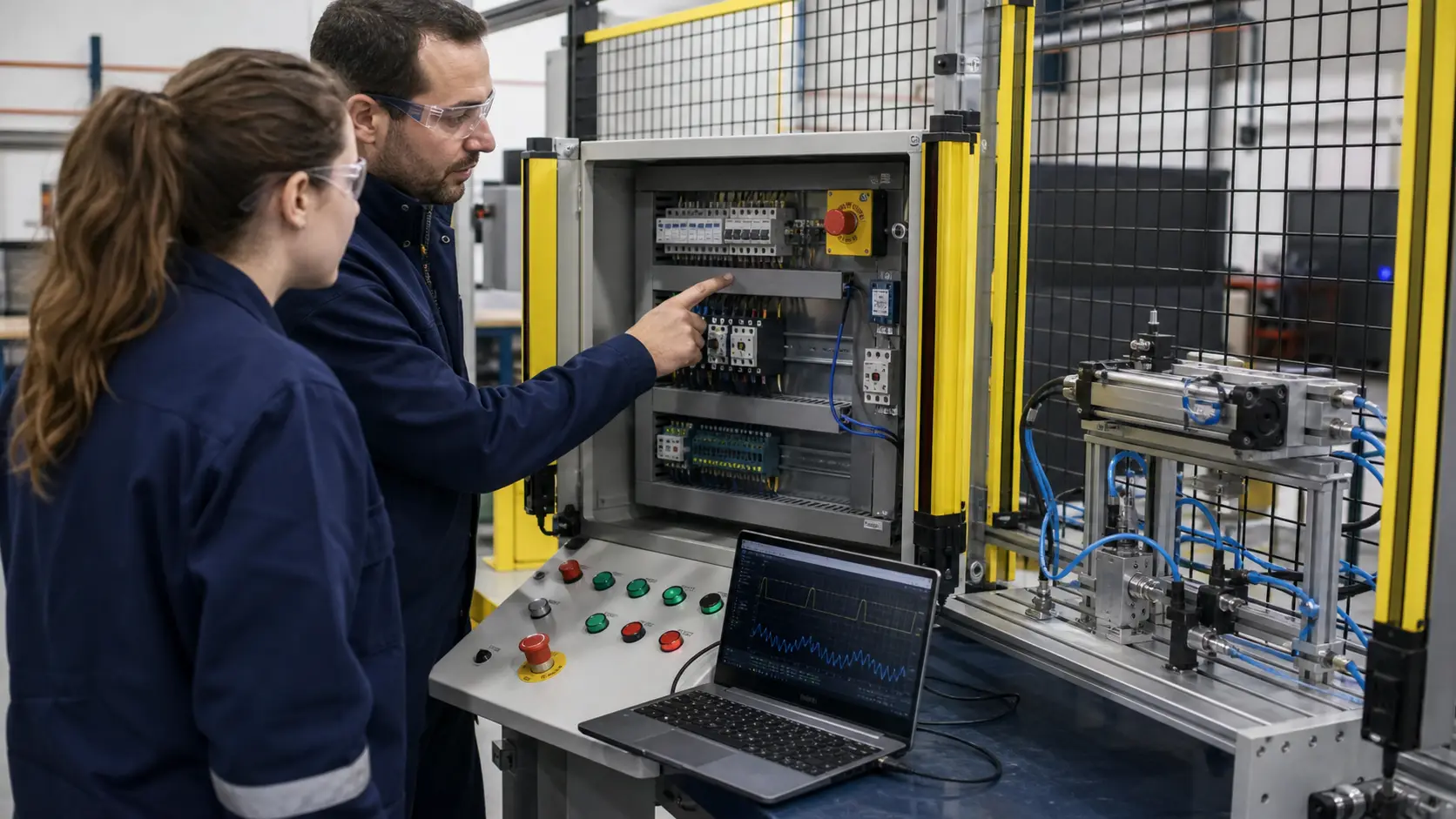
Required stroke, force, speed, load, pressure, bore, rod, mounting, valve type, flow control, cushions, end sensors, trapped energy and safe state.
PLC command through output interface, solenoid valve, airflow, cylinder motion, end position, sensor feedback and sequence transition.
Repeatable extend, prove, dwell, retract and prove cycle at the declared pressure and load.
Low pressure, blocked exhaust, reversed flow control, sticky spool, leak, sensor misalignment, stalled motion, lost power and restart.
An air-supply, valve, tubing, cylinder, mechanics, sensor, output, sequence or feedback mismatch.
The actuator sized and validated with current component data, guarding and machine risk controls.
The PLC drives a valve interface; the valve routes compressed air and position sensors provide separate evidence that the cylinder reached the expected state.
Flow-control orientation, restriction, load, pressure, leakage, valve state, cushioning or mechanical binding can affect one direction differently.